


- Accueil
- 78 (2022/1) - De la géomorphologie à la géomatique...
- The dark side of the remote sensing: current SAR remote sensing missions and applications


Visualisation(s): 2729 (17 ULiège)
Téléchargement(s): 176 (1 ULiège)

The dark side of the remote sensing: current SAR remote sensing missions and applications

Document(s) associé(s)
Version PDF originaleRésumé
Ce papier présente un aperçu des concepts liés au radar à synthèse d’ouverture (SAR en anglais). La télédétection SAR est une technique d’imagerie cohérente où le senseur émet un rayonnement électromagnétique, et enregistre le signal rétrodiffusé. Chaque pixel de l’image contient une information sur la capacité de la cible au sol à rétrodiffuser le signal, et une information sur la distance satellite – cible au sol. Dans un premier temps, nous passerons en revue les concepts du SAR et de l’interférométrie SAR. Nous verrons qu’il existe un grand nombre de différences par rapport à la télédétection optique : la géométrie d’acquisition, les longueurs d’ondes employées, les soucis de la résolution spatiale, la polarisation, etc. De plus, nous nous intéresserons aux applications employant l’information de phase, comme l’extraction de modèles numériques de terrain (MNT) ou de cartes de déplacements. Dans un second temps, nous discuterons des missions SAR actuelles et futures, ainsi qu’un nombre d’applications provenant du monde de l’apprentissage en profondeur. Le domaine du SAR évolue rapidement, et de plus en plus de satellites sont en développement. Le secteur privé investit massivement, s’attaquant à un marché orienté services. En parallèle, les grandes institutions publiques disposent déjà de satellites SAR importants, et précisent les spécifications techniques des nouvelles générations.
Abstract
The present paper provides an overview of Synthetic Aperture Radar (SAR) remote sensing concepts. SAR remote sensing is a coherent active imaging technique, where the spaceborne sensor emits an electromagnetic wave and captures its backscattered signal. Each pixel contains amplitude information, witness of the ground properties to reflect the signal back to the sensor, and a phase component, which is related to the distance from the sensor to the ground target. Firstly, we will focus on SAR and SAR interferometry concepts. The acquisition geometry, the different wavelengths, the issue of spatial resolution, the polarization; SAR has a number of differences compared to optical remote sensing. In addition, the coherent imaging technique allows the exploitation of the phase information, with applications such as DEM generation or surface displacements retrieval. In a second part, we will discuss the current and future SAR constellations as well as recent advances in applications coming from the deep learning field. The domain of SAR remote sensing is a rapidly evolving field, where more and more satellites are being set up and where the private sector is investing massively. Service-oriented market using small X-Band SAR satellites is getting more and more present. In parallel, public institutions already have several important SAR satellites and are currently preparing the next generation, with improved technical specifications.
Table des matières
Introduction
1The term dark in dark side of remote sensing refers to two elements of Synthetic Aperture Radar (SAR) remote sensing.
2First, as we will see, SAR is an active imaging technique. It is not the only one, as altimeters are also active spaceborne sensors. Nevertheless, SAR produces images that share visual similarities with more classical remote sensing, such as images produced by optical satellites (Landsat 8, Sentinel-2, or Pléiades). SAR sensors emit pulsed electromagnetic waves in the radio frequencies and capture the echoed signal. Contrary to optical remote sensing, SAR does not capture the reflected solar radiation. SAR is therefore completely independent of the Sun illumination, and is perfectly capable of working in dark conditions such as during the night. This is particularly useful in polar regions, where areas of interest are subject to multi-month length nights, where optical sensors become unusable.
3The dark side also refers to the relative quietness of SAR remote sensing in the classes in environmental sciences studies. This is understandable, in the sense that remote sensing is already a highly transverse field that merges physics, mathematics and computer science. Depending on the objectives, we will also need backgrounds in biology, chemistry, and geosciences. In remote sensing lessons, the student will encounter topics such as optics, celestial mechanics, radiative transfer, and digital signal processing. With a focus on methods, the students will also face subjects related to computer vision, such as data visualization, multivariate statistics, machine learning and so forth. In a user-oriented approach, the students will finally need additional specificities related to its application; crop yield estimation requires biology / agronomy backgrounds; cryosphere monitoring requires glaciology; atmosphere composition requires chemistry and climatology. In this ocean of possibilities, and limited hours to give a proper remote sensing class, professors have to purposely omit branches of remote sensing. SAR remote sensing is often one of them, especially the deeper SAR interferometry domain. Nevertheless, we are observing a shift in this trend, as SAR was the first priority of the European Space Agency Copernicus program, and we now occasionally see SAR content in general remote sensing courses.
I. SAR and INSAR concepts
4In optical remote sensing, the Sun illuminates the Earth surface in its entire wavelength spectrum. The ground backscatters a part of the energy received. The satellite picks up the backscattered signal and records the light intensity according to the sensitive spectrum of the sensor (Elachi & IEEE, 1987).
5Unlike optical remote sensing, SAR sensors generate their own radiation, with a given frequency and polarization, which is then backscattered by the ground and received by the sensor (Elachi & van Zyl, 2006). Moreover, radar authorizes work day and night, through clouds, and to study geophysical processes at a given frequency. For instance in Belgium, due to cloud coverage, it allows increasing the number of potential usable acquisitions by one order of magnitude.
6Radar remote sensing includes a series of bands between 1 and 40 GHz (Table 1), each frequency having specific properties. In general, a signal reacts strongly with geometries of size comparable to the wavelength used, determining the range of applications (topography, cryosphere, biomass, and so on). For the example of forestry, small wavelengths (X band) will be stopped by the canopy while long wavelengths (L to P bands) pass through the canopy and interact with the soil, trunks, or large branches.
|
Radar Band |
Frequency (GHz) |
Wavelength (cm) |
|
Ka |
26.5–40 |
1.1–0.75 |
|
K |
18–26.5 |
1.7–1.1 |
|
Ku |
12.5–18 |
2.4–1.7 |
|
X |
8–12.5 |
3.75–2.4 |
|
C |
4–8 |
7.5–3.75 |
|
S |
2–4 |
15–7.5 |
|
L |
1–2 |
30–15 |
|
P |
0.3–1 |
100–30 |
Table 1. Common radar frequencies employed in SAR remote sensing (Parker, 2010)
7The satellite moves by illuminating one of its sides. SAR sensors are said to be side-looking. In a SAR image, one dimension of the image corresponds to the flight direction, called the azimuth direction, and the other to the range, meaning the distance from the sensors to the target. Contrary to optical images, the pixel location in a SAR image does not correspond to the sight-angle of the sensor, but to a distance, here called the slant range.
8In terms of spatial resolution, radar wavelengths do not allow to reach fine pixel spacing. Resolution is linearly dependent on the distance and the wavelength, and inversely linearly dependent on the antenna size. Using typical C-band SAR sensors, a kilometric resolution in the range direction is obtained. It is possible to narrow the beam and achieve the metric spatial resolution using Synthetic Aperture Radar (SAR), by combining the different echoes emitted by the sensor. This is called the focusing operation. From this, the image is said to go from RAW (L0) to Single-Look-Complex, or SLC (L1).
9The choice of the acquisition strategy also has an influence on the spatial resolution. We generally separate them into three modes: Stripmap, Spotlight and ScanSAR/TOPSAR. In Stripmap mode, the satellite is illuminating the scene at a fixed look angle. Spotlight, in contrary, is focusing on a more restraint area by increasing the aperture time. It allows the sensor to drastically increase the spatial resolution in this specific region. In TOPSAR and ScanSAR modes, SAR sensors electronically steer their antenna on a wider region to increase spatial coverage at a cost of spatial resolution. In the end, the balance between spatial resolution and coverage is application dependent, and determines the acquisition mode.
II. Amplitude information
10A SAR image is a complex image, made up of phase information and amplitude information (Eckardt et al., 2013).
11The amplitude depends on the backscattering mechanisms of the target. Typically, the amplitude of the backscattered signal is linked to a couple of parameters specific to the object: rugosity and moisture. In addition, it is affected by the acquisition geometry, in particular the angle between the normal to the slope and the sight-direction of the sensor. One example is the double bounce effect. When the electromagnetic wave meets two perpendicular smooth surfaces, the beam is reflected back to the sensor with maximum amplitude (Figure 1). This effect is very common in urban areas. Radar amplitude has a range of important applications in oceanography, land use, urban planning or ecology.
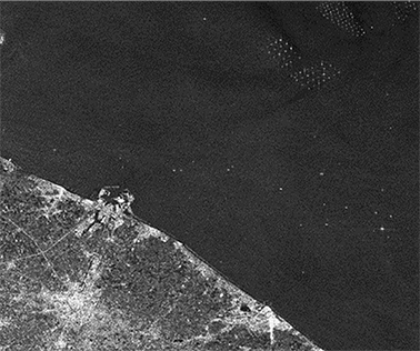
Figure 1. Double bounce effect, revealing anthropogenic structures: buildings, offshore wind turbines and boats (illustration from Sentinel-1 over the Belgian coast)
12Unlike optical imaging, the position of a pixel in SAR depends on the distance from the sensor. A consequence is that topography influences the distance between an object on the ground and the sensor, inducing geometric distortions. We generally distinguish three types of geometric distortions: foreshortening, layover and shadowing.
13Foreshortening occurs when higher altitudes are closer to the sensor; therefore, they appear at an inadequate place within the image. An extreme case of foreshortening is layover, where the summit of a target (e.g. mountain, building) is seen before the base of the element, shifting the pixel location of the summit and creating ghost artefacts. Topography can obstruct parts of the observed scene, creating a shadow area in the image, and hence a shadowing effect. Hidden pixels appear black since, for a given distance, no backscatter is recorded.
14SAR images are characterized by an additive deterministic noise called speckle. The return signal of a pixel contains each of the contributions of the ground diffusers, the variability of which creates a speckle effect. The speckle has a statistical distribution centered around zero, and can therefore be reduced by spatial or temporal aggregation. This technique is called multilooking (spatial or temporal – Figure 2).
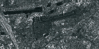
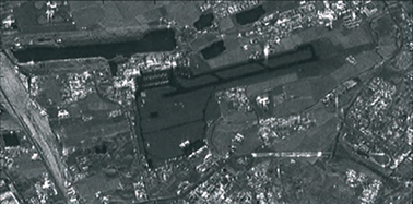
Figure 2. Speckle noise reduction using temporal multilooking (illustration from Ferreti et al., 2007)
15The satellite sends out a pulsed electromagnetic wave, containing an electric field and, perpendicular, a magnetic field. The sensor can control the direction of polarization of the sent signal and the return signal. Examples:
16• VV: vertical transmit, vertical receive;
17• VH: vertical transmit, horizontal receive.
18The ground material is capable of depolarizing the received signal. The combination of signals with different polarizations provides information, and so the difference in intensity between the received signals of different polarizations makes it possible to discriminate between classes on the ground. For example, anthropogenic elements tend to return a signal that is not depolarized while vegetated structures tend to depolarize the signal (Figure 3).
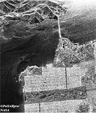
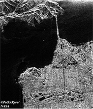
Figure 3. VV and VH images of San Francisco Anthropogenic elements tend to return a signal that is not depolarized; on the contrary, vegetated structures tend to depolarize the signal (illustration from NASA)
III. Phase information
19The phase information is proportional to the distance between the satellite and the target on the ground, traveled by the electromagnetic wave. Based on two SAR images taken from two similar points of view, it is possible to reconstruct the topography of the place. The first image is at a distance r from the target. The second is at a distance r + δr (Figure 4).
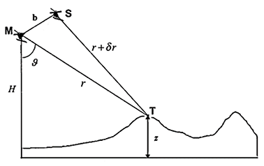
Figure 4. Interferogram formation based on two sensors M and S, separated by a distance b; M is at a distance r from the target, S is at a distance r + δr (illustration from Pepe & Calò, 2017)
20An interferogram consists in the combination of signals to reveal the phase difference between the two images (Pepe & Calò, 2017). This phase difference is called the interferometric phase and is proportional to the distance difference 𝜹 r between the two images.
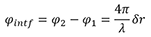
21The phase difference varies continuously with 𝜹 r. Even without topography, the interferometric phase has a component that depends on the viewing angle and the sensor positions. At the same time, the topography also modifies the path difference between the target and the sensors. There are a large number of terms to consider in SAR interferometry, some of which can be calculated and removed. In order, we can enumerate the orbital phase, the topographic phase, the displacement phase, the atmospheric phase screen, and finally a component that comprises the residual noise (Equation 2).

22One important note is that the interferometric phase is known modulo 2π, which implies a phase unwrapping operation to determine the absolute phase. The fringe sensitivity is determined by two parameters: the wavelength and the baseline. Larger baselines increase sensitivity to height, while longer wavelengths decrease the sensitivity to topography and displacements. Once unwrapped, the topographic phase can be translated into a digital terrain model (Figure 5).
23Several missions allowed the creation of digital terrain models via SAR interferometry. The Shuttle Radar Topography Mission (SRTM) was a mission conducted by performing SAR interferometry by taking two simultaneous acquisitions at each end of a 60 meters mechanical arm attached to the NASA Space Shuttle. In this bistatic configuration, it is possible to neglect the effect of displacements and the atmospheric phase screen. The SRTM allowed the creation of a global Digital Elevation Model (DEM) of the Earth (from -60 to +60 degrees latitude).
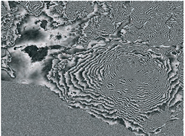
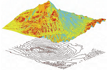
Figure 5. Topographic phase component (top) and DEM extraction from the unwrapped phase (bottom) (illustration from Ferretti et al., 2007)
24The quality of an interferogram can vary greatly; coherence is a local measure of quality. It is defined by the complex correlation between the master image and the slave image. A correlation value of 1 means perfect consistency between the images, with perfectly distinguishable and unwrappable fringes. A 0 correlation means a change in the arrangement of ground scatterers, a witness of changes in the ground conditions between the two acquisitions, resulting in a loss of coherence. This type of signal cannot be used for SAR interferometry.
25One of the sources of decorrelation is the time that separates the two acquisitions, creating a temporal decorrelation. Another source of decorrelation is related to acquisition geometry, which influences the fringe sensitivity. Thermal noise also induces an additional decorrelation pattern in the interferogram. More importantly, a sudden loss of coherence between successive dates is also a sign of land cover change.
26Finally, one very important branch of SAR is Differential SAR Interferometry (DInSAR). By using two images taken at different times, it is possible to determine the movement of a target on the ground. If we know the topography (by using a DEM for example), it is also possible to determine a movement along the line of sight of the satellite. To achieve this, we can remove the topographic phase component from the interferometric phase. As long as the atmospheric influence is negligible (or correctable), this residual phase term can be translated into movement (Ferretti et al., 2007).
27Differential interferometry is very sensitive to displacements and is able to determine sub-centimetric movements. Similar to topography, the fringes can be unrolled and converted to a displacement map. One very famous example of displacement estimation is the Landers Earthquake event, making the cover page of the Nature journal (Massonet et al., 1993).
IV. Current and future SAR missions
28In the early 2000s, the European Space Agency developed its strategic plan in their Earth Observation department. Rapidly, three pillars emerged: Copernicus, Meteorology and Earth Explorer. The Copernicus program includes well-known techniques with a particular focus on user-oriented applications. Copernicus is composed of a set of Sentinels, decomposed into Sentinel-1 to Sentinel-6, each having their particular sensors and objectives.
29Sentinel-1 is the workhorse of the SAR part of the Copernicus program (Torres et al., 2012). Currently, two Sentinel-1 are orbiting the Earth (S-1A and S-1B), and are positioned to reduce the revisit time by half (6 days). Sentinel-1 aims at the systematic observation of the Earth in the C-Band radar frequency (5.45 GHz), with low latency. To obtain this small revisit time, Sentinel-1 is characterized by a specific acquisition mode, called TOSPAR, allowing large swath width, ranging from 250 to 400 km, with a decametric resolution.
30Sentinel-1 data is accessible free-of-charge by the Open Access Hub, or by mirror data facilities (Operating platform Sentinel products – PEPS, Alaska Satellite Facility, etc.). Sentinel’s derived products are available through the different services offered by the Copernicus program (atmosphere, climate change, emergency, land, marine, security) through the Copernicus Service Hub. The Copernicus program brought about 500 000 users, that have access to petabytes of data. In the end, Copernicus is an ambitious program that provides remote sensing data fluxes to the public (Figure 6). It is the user’s responsibility to create added value from operational services. Started in 2014 with S-1A, long time series are already available.
31To encourage user developments and education, the European Space Agency funded open-source toolboxes through the SentiNel-Application Platform – SNAP (Brockmann Consult, 2020). SNAP is a multi-mission remote sensing software originally designed for the different Sentinel products but now updated for other sensors (ALOS, TerraSAR, CosmoSkymed, etc.). All source codes are available online in a DevOps environment. Users are allowed to download and commit changes to the project. SNAP has more than 800 000 downloads and is currently the most popular remote sensing software. SNAP functionalities are varied, and enable data calibration, speckle filtering, co-registration, interferometry, multilooking, terrain correction, and so on. SNAP is also linked with other popular routines or software such as STAMPS (Mancini et al., 2021) for permanent scatterer interferometry, or PolSARPro (Pottier et al., 2009) for advanced polarimetric techniques. SNAP is using the BEAM-DIMAP image format, easy to combine with GIS software such as QGIS. For advanced operational services, SNAP allows the development of processing frameworks, thanks to graph processing tools and batch processing operations. Finally, it has a large user support material, with tutorials on various subjects such as SAR interferometry or flood mapping.
32Since the launch of Sentinel-1, the number of Earth observation users drastically increased, with limited experience in SAR and SAR interferometry. In particular, SAR is inherently a non-trivial field of remote sensing, with a specific acquisition scheme, synthetic aperture or coherent imaging representation. In response, the National Aeronautics and Space Administration (NASA) developed the openSARLab, a cloud-based SAR training tool environment, using Amazon Web Services (AWS) and Jupyter Notebooks. It also contains a number of books and materials available. Among these books, we recommend the very exhaustive and practical SAR Handbook: Comprehensive Methodologies for Forest Monitoring and Biomass Estimation (Flores et al., 2019).
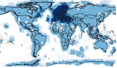
Figure 6. Heatmap of Sentinel-1 SLC products published from the start of operations to the end of 2019 (Hajduch et al., 2020)
33Sentinel-1 A and B were launched in 2014 and 2016. They were designed for a 7-year mission, with 5 years of additional consumables. As there are currently approaching the end of their lifetime, their successors, Sentinel-1 C and D, are being prepared, with minor modifications compared to their predecessors (Torres et al., 2021). S-1C is scheduled to be launched in 2022. The question about the acquisition geometry of the Sentinel-1 remains. Currently, each Sentinel-1 satellite has a 12 day revisit time. Coupled, S-1A and B reduce it to 6 days. By repositioning S1-B to a new orbit, it is possible to use S1-A, B, and C, with a revisit time down to 4 days (4/4/4 formation). Another option is to keep the current Sentinel-1 constellation unchanged, and place S1-C 1, 2 or 3 days after Sentinel-1 A (1/5/6, 2/4/6, or 3/3/6 formation scenario). Historically, the ERS mission, in the 1990s, brought a similar acquisition scheme during the TANDEM mission, with two ERS satellites separated by 1 day. This type of configuration is extremely beneficial to study highly dynamic patterns, such as present in the cryosphere domain.
34Originally, 6 Sentinel families were planned. Due to the success of the program, 6 additional missions were added as part of the Copernicus Expansion Program. Among them, an additional SAR mission, called ROSE-L, was defined (Davidson & Furnell, 2021). In parallel to the Sentinel-1 mission, the future ROSE-L mission comes as complementary information in the L-band SAR frequencies and fills the observation gaps described in scientific literature (Lancheros et al., 2018). ROSE-L is in preparation and is scheduled for launch around 2028. ROSE-L will contain up to 3 satellites, each having 12 days revisit time. Acquisition geometry and mission objectives are similar to the Sentinel-1 mission, but the larger wavelength is an important added value to produce deformation maps, sea ice classification, forest monitoring, as well as food security assessment. L-Band is also less impacted by temporal decorrelation.
35Finally, SING (Sentinel-1 Next Generation), is in preparation. S1NG is part of a long-term scenario that ensures the continuity of the C-band SAR acquisition at least up to 2037 (Torres et al., 2021). Sentinel-1 Next Generation brings important enhancements in their specifications: better spatial resolution, larger swath, better radar sensitivity, decreased revisit time, increased duty cycle and so on. In addition, the multichannel SAR system will allow onboard along-track interferometry.
36The Japan Aerospace Exploration Agency (JAXA) also developed spaceborne SAR sensors. They rapidly specialized in the L band frequencies with first the JERS1 satellite in 1992, then ALOS in 2006, and ALOS2 in 2014. JAXA is currently preparing ALOS4, which is also a phased array-type L-band SAR sensor (Shibata et al., 2021). With land observation as a key target, ALOS and ALOS2 participated in the development of wide swath imaging sensors. Objectives of their sensor range from land deformation monitoring to environmental monitoring in general. The next sensor ALOS4 is planned to have a 700 km swath in ScanSAR mode with a pixel spacing of 25 meters. In Stripmap acquisition mode, the new onboard digital beamforming unit will allow the acquisition of 200 km swaths at 3 meters resolution.
37The German Aerospace Center (DLR) is part of the official partner institution of the European Space Agency. In 2007, they launched the TerraSAR-X satellite, operating – as the name suggests – in the X-band SAR frequencies and providing high-resolution products (Zink et al., 2006). In 2010, a second X-band SAR satellite, similar to the first, was launched with the objective of flying in bistatic configuration with the first TerraSAR-X (Krieger et al., 2007). The formation – called TanDEM-X – has the ability to perform SAR interferometry without temporal decorrelation. A global DEM was computed from data ranging from 2010 to 2015 with 12 meters posting. A revision using data from 2017 to 2020 is in preparation. Moreover, the TanDEM-X mission was also a laboratory for new acquisition modes. It allowed the development of the TOPSAR acquisition mode, which is the default mode in the Sentinel-1 satellites.
38The TanDEM-X mission largely overpassed its mission life expectancy. DLR is preparing the future of the German SAR Earth observation throughout the HRWS for High Resolution – Wide Swath, satellite (Nuncio Quiroz & Bartusch, 2019). HWRS offers a resolution of up to 25 cm and wide swath acquisition modes. The specificity of HWRS is a formation flying mode, with one active sensor and three passive companions (receive-only satellites). The technology is based on a mirror-SAR system, allowing a very large bandwidth (1 200 MHz). The different acquisition modes can balance spatial resolution, polarization and coverage, with spotlight and Stripmap modes for sub-metric resolution for urban applications, and ScanSAR modes for a coverage up to 1 000 km. In the end, a 4 meters posting global DEM is planed during the lifespan of the mission. A similar concept is also in preparation as part of the Earth Explorer pillar of the ESA Earth observation. Indeed, the Harmony mission is studying the added value of lightweight passive companions to Sentinel-1. Finally, the mission aims at resolving Line-Of-Sight diversity issues and providing 3D-DInSAR.
39Spain also has an important Earth observation program, which includes the PAZ satellite (Alonso-Gonzalez et al., 2021). PAZ is an X-Band SAR satellite based on the German TerraSAR-X. Both are almost identical and can be used together. By doing so, it is possible to reduce the revisit time from 11 days to 4 or 7 days. This allows important coherence gains and the study of dynamic events.
40The Agenzia Spaziale Italiane (ASI) presents a future roadmap of their Earth observation strategy (Formaro et al., 2021). ASI has a long legacy of SAR products, thanks to their Cosmo-Skymed constellation consisting of 4 X-Band SAR spaceborne sensors. With the first satellite launched in 2007, ASI is preparing the second generation of Cosmo-Skymed (called CSG) constellation. The first two new satellites were launched in 2019 and 2021. The third and fourth are in preparation. In parallel, the ASI is pursuing developments in geosynchronous SAR, airborne L and P band SAR (experiments before space developments), SAR minisatellites (Platino-1). Finally, ASI is designing their specifications for a future generation of Cosmo-Skymed, following the CSG program.
41NASA is among the precursors in SAR, with the SIR and SRTM missions. Since then, NASA has been quite silent in terms of spaceborne SAR sensors. In collaboration with the Indian Space Research Organization (ISRO), NASA is developing the NASA ISRO SAR (NISAR) mission to answer the National Imperatives for the Next Decade and Beyond (National Research Council, 2007). The NISAR mission aims at providing global, free, and open SAR data, in a mindset similar to what Sentinel-1 is doing. The specificity of NISAR is that the satellite is equipped with a dual-frequency sensor, operating in S- and L-bands simultaneously (Kellogg et al., 2020). The applications are varied, including surface deformation (faults, volcanoes, landslides, subsidence, uplifts), soil moisture, vegetation, ice sheet / ice shelves, sea ice, etc. The launch is currently scheduled for January 2023.
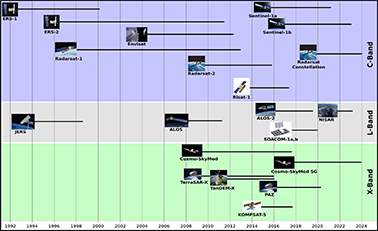
Figure 7. Timeline of current and future popular SAR missions (UNAVCO, 2019)
42There are many SAR satellites from other important institutions. It is worth mentioning RADARSAT, from the Canadian Space Agency (CSA). RADARSAT is a C-band SAR spaceborne sensor. With the successful RADARSAT and RADARSAT-2 missions (launched in 1995 and 2007, respectively), CSA launched in 2019 the RADARSAT Constellation, a set of three C-band SAR satellites which, coupled, have a revisit time of 4 days. One must also mention KompSAT-5, a Korean satellite launched in 2013 providing high-resolution X-Band SAR data. It is finally difficult not to talk about the SAOCOM mission, in which the Liège Space Center participated. SAOCOM-1A and 1B are full-polarization L-Band SAR satellites respectively launched in October 2018 and August 2020 by the Argentinian National Space Activities Commission (CONAE).
43Finally, the private sector increasingly enters the space industry. With the emergence of Newspace, a number of commercial applications appeared. Newspace is characterized by a drastic reduction of development costs, allowing non-institutional services to enter the market. Recently, Newspace also includes SAR remote sensing. Six private companies are already present in this sector, with more coming. Among them, Capella, Synspective or predaSAR can be mentioned. The first SAR satellite belonging to this trend is ICEYE X1, a SAR satellite of 85 kilograms launched in 2018 (Ignatenko et al., 2020). In July 2021, 13 micro SAR satellites are orbiting the Earth. To this day, several hundreds of satellites are being developed.
44The goal of this Newspace trend is to develop SAR in space at a low cost. To put in perspective, small SAR satellites cost around 10 M$, while important projects led by ESA, NASA, or JAXA largely overpass the 100 M$ price tag. These low-cost satellites encourage the formation of mini-satellite constellations, which drastically enhance the revisit time. As an example, the 30 satellites of ICEYE-X1 can reduce the revisit time to less than 1 day. In the end, these types of SAR constellations greatly decrease the latency and allow operability 24/7.
45Capella is typical example of this Newspace industry. The company is producing small SAR satellites in X-Band. Using spotlight acquisition mode and large bandwidth, the images can reach the 50 cm spatial resolution (Stringham et al., 2019). The commercial activities are ensured by on-demand self-service requests. In three months, the satellite produced 3 000 images.
46The Japanese company Synspective also joined the race of small SAR satellites with its recently launched StriX-α X-band SAR satellite (Obata et al., 2020). StriX-α aims at a sub-daily revisit time, at one meter spatial resolution. A constellation of 6 satellites is scheduled for 2022, with a final objective of 30 satellites.
47Finally, Airbus is also developing active, responsive, and reconfigurable spaceborne sensors. Launched in 2018, the NOVASAR satellite is an S-band SAR sensor with large bandwidth (Zhou et al., 2020).
48Small satellites are also more accessible to governments or smaller public institutions. The Portugal government developed the Atlantis project, a constellation of very small 16U X-band SAR satellites (less than 30 kilograms), with the objectives of monitoring oil spills, surface currents, sea ice or iceberg calving (Portuguese Space Agency, 2020). One key limitation of small SAR satellites is the coverage. Capella limits its coverage to 5 x 10 kilometers. ICEYE is one exception in this category in the sense that the engineers implemented a TOPSAR acquisition mode to increase the swath of the image. This is balanced by the relative low resolution of the sensor. International agencies, such as ESA, are well aware of the exponential growth of the small satellite market. These agencies need to position themselves in this dynamic trend.
V. Deep learning advances
49The amount of available data also brings new technical developments that come from the big data world and artificial intelligence (AI). With the growing data flux, these types of techniques are becoming mandatory to filter information from multi-petaoctets datacubes.
50Andrew Ng, in an interview, wrote “AI is the electricity of the XXI’s century” (Graduate School of Stanford Business, 2017). AI indeed invaded multiple scientific domains. Though AI has been an important part of the computer vision world for a long time, it is only recently that machine and deep learning algorithms are an everyday component of remote sensing applications (Zhu et al., 2017).
51Remote sensing is still facing a series of challenges in terms of deep learning. The first problem arose because of the size of SAR acquisitions. Each Sentinel-1 SLC image is several gigaoctets, on temporal scales of several years and a potential large coverage. Remote sensing combined with deep learning automatically requires important processing infrastructures. Nevertheless, popular deep learning networks emerged in remote sensing: FCN, PCANet, U-net, DeepUnet, YOLOv3 or HRnet are now frequently cited in the literature (Gao et al., 2016; Gong et al., 2016; Li et al., 2018; Baumhoer et al., 2019; Chang et al., 2019; Liu et al., 2019; Wang et al., 2019; Dalsasso et al., 2020). Solutions generally require the creation of superposed sub-images to reduce the complexity or temporal clustering of image sets into mini-stacks (Gaddes et al., 2019; Ho et al., 2021).
52A second problem comes from the lack of training data. In computer vision, large datasets of images with associated labels exist. This took a long time for remote sensing to have access to this type of data. Still nowadays, the problem of labels availability is present in remote sensing applications. Data augmentation techniques exist to artificially increase the number of training samples. Rotation and mirror operations are such examples. In addition, remote sensing has weak labels issues. In the computer science domain, it is common to have a 1 – to – 1 correspondence between the image and the label (Chen et al., 2019). In remote sensing, the correspondence is much more debatable. This is particularly the case in SAR remote sensing where speckle noise introduces a lot of variety, making the image features difficult to extract.
53The inclusion of artificial intelligence in remote sensing needs to deal with a very limited number of weak labels, on powerful computing stations.
Conclusion
54Synthetic Aperture Radar is a unique branch of remote sensing. The specificities of radar wavelength make its acquisition geometry and processing quite particular. More specifically, a prior focusing operation is mandatory, contrary to optical remote sensing. SAR images also have uncommon properties. Due to the wavelength employed, radar is able to penetrate through clouds and with the absence of solar illumination. In addition, radar brings new information about the characteristics of the ground. In this paper, we summarized the basic concepts of SAR and SAR interferometry. We also presented a series of applications.
55In a second part, we presented the different sensors that are used nowadays and a schedule on the ongoing SAR activities. Important public institutions are present, but the recent Newspace era makes the entry of the private sector into the space domain, with service-oriented low-cost satellite constellations.
Acknowledgements
56Christian Barbier is acknowledged for providing advice and support. This research is supported by the French Community of Belgium in the funding context of a FRIA grant, and carried out in the framework of the MIMO (Monitoring melt where Ice Meets Ocean) project funded by the Belgian Science Policy contract No. SR/00/336.
References
57Alonso-Gonzalez, A., Hajnsek, I., Grigorov, C., Roth, A., Marschalk, U., Gimeno Martinez, N., Cifuentes Revenga, P., Gonzalez Bonilla, M. J., Casal Vazquez, N., Cuerda, J. M. & Gracia Rodriguez, M. (2021). Joint PAZ and TanDEM-X Missions Interferometric Performance. In Davidson, M.W.J. & Furnell, R. (eds), IGARSS 2021 - 2021 IEEE International Geoscience and Remote Sensing Symposium, Brussels, 792–795.
58Baumhoer, C. A., Dietz, A. J., Kneisel, C. & Kuenzer, C. (2019). Automated extraction of antarctic glacier and ice shelf fronts from Sentinel-1 imagery using deep learning. Remote Sensing, 11 (21), 1–22. https://doi.org/10.3390/rs11212529
59Brockmann Consult (2020). Skywatch, Sensar and C-S. SNAP - ESA Sentinel Application Platform v8.0.3 (Computer Software).
60http://step.esa.int/. Retrieved 14 October 2021.
61Chang, Y. L., Anagaw, A., Chang, L., Wang, Y. C., Hsiao, C. Y. & Lee, W. H. (2019). Ship detection based on YOLOv2 for SAR imagery. Remote Sensing, 11 (7).
62https://doi.org/10.3390/rs11070786
63Chen, W. Y., Wang, Y. C. F., Liu, Y. C., Kira, Z. & Huang, J. B. (2019). A closer look at few-shot classification. 7th International Conference on Learning Representations (ICLR 2019, 2018), 1–17.
64Dalsasso, E., Yang, X., Denis, L., Tupin, F. & Yang, W. (2020). SAR image despeckling by deep neural networks: From a pre-trained model to an end-to-end training strategy. Remote Sensing, 12 (16), 1–19.
65https://doi.org/10.3390/RS12162636
66Davidson, M. & Furnell, R. (2021). ROSE-L : Copernicus l-band SAR mission. In Davidson, M.W.J. & Furnell, R. (eds), IGARSS 2021 - 2021 IEEE International Geoscience and Remote Sensing Symposium, Brussels, 872–873.
67Eckardt, R., Richter, N., Auer, S., Eineder, M., Roth, A., Hajnsek, I., Walter, D., Braun, M., Motagh, M., Pathe, C., Pleskachevsky, A., Thiel, C. & Schmullius, C. (2013). SAR-EDU - An education initiative for applied Synthetic Aperture Radar remote sensing. In 2012 IEEE International Geoscience and Remote Sensing Symposium, 5315-5317. https://doi.org/10.1109/IGARSS.2012.6352408
68Elachi, C. & IEEE Geoscience and Remote Sensing Society (1987). Spaceborne radar remote sensing: Applications and techniques. New York: IEEE Press, 11-50.
69Elachi, C. & van Zyl, J. (2006). Nature and Properties of Electromagnetic Waves. In Kong, J.A., Elachi, C. & van Zyl, J. (eds), Introduction to the Physics and Techniques of Remote Sensing, 23-50. https://doi.org/10.1002/0471783390.ch2.
70Ferretti, A., Monti-Guarnieri, A., Prati, C., Rocca, F. & Massonnet, D. (2007). InSAR Principles: Guidelines for SAR Interferometry Processing and Interpretation (ESA TM-19). ESA Publications, A9-B71.
71Flores, A., Herndon, K., Thapa, R. & Cherrington, E. (2019). The SAR Handbook: Comprehensive Methodologies for Forest Monitoring and Biomass Estimation. https://doi.org/10.25966/nr2c-s697. Retrieved 14 October 2021.
72Formaro, R., Longo, F., Varacalli, G., Fasano, L. & Pulcino, V. (2021). ASI roadmap in technology and programmes for earth advanced monitoring and assessment of hazards. In Davidson, M.W.J. & Furnell, R. (eds), IGARSS 2021 - 2021 IEEE International Geoscience and Remote Sensing Symposium, Brussels, 1875–1878.
73Gaddes, M. E., Hooper, A. & Bagnardi, M. (2019). Using Machine Learning to Automatically Detect Volcanic Unrest in a Time Series of Interferograms. Journal of Geophysical Research: Solid Earth, 124 (11), 12304–12322. https://doi.org/10.1029/2019JB017519
74Gao, F., Dong, J., Li, B. & Xu, Q. (2016). Automatic Change Detection in Synthetic Aperture Radar Images Based on PCANet. IEEE Geoscience and Remote Sensing Letters, 13 (12), 1792–1796.
75https://doi.org/10.1109/LGRS.2016.2611001
76Gong, M., Zhao, J., Liu, J., Miao, Q. & Jiao, L. (2016). Change Detection in Synthetic Aperture Radar Images Based on Deep Neural Networks. IEEE Transactions on Neural Networks and Learning Systems, 27 (1), 125-138, doi: 10.1109/TNNLS.2015.2435783.
77Graduate School of Stanford Business (2017). Andrew Ng: Why AI Is the New Electricity (Press Release, March 11, 2017). http://stanford.io/2mwODQU. Retrieved 14 October 2021.
78Hajduch, G., Vincent, P., Meadows, P., Small, D., Pilgrim, A., Schubert, A., Piantanida, R., Recchia, A., Franceschi, N., Mouche, A., Grouazel, A. & Husson, R. (2020). Sentinel-1-Annual-Performance-Report-2019. Sentinel-1 Mission Performance Centre, Report DI-MPC-APR / MPC-0460, version 1.1.
79https://doi.org/10.13140/RG.2.2.28472.16646
80Ho, D., Minh, T. & Ngo, Y. (2021). ComSAR: a new algorithm for processing Big Data SAR Interferometry. In Davidson, M.W.J. & Furnell, R. (eds), 2021 IGARSS 2021 - IEEE International Geoscience and Remote Sensing Symposium, Brussels, 820–823.
81Ignatenko, V., Laurila, P., Radius, A., Lamentowski, L., Antropov, O. & Muff, D. (2020). ICEYE Microsatellite SAR Constellation Status Update: Evaluation of First Commercial Imaging Modes. In IGARSS 2020 - 2020 IEEE International Geoscience and Remote Sensing Symposium, Waikoloa, (HI), 3581–3584.
82https://doi.org/10.1109/IGARSS39084.2020.9324531
83Kellogg, K., Rosen, P., Barela, P., Hoffman, P., Edelstein, W., Standley, S., Dunn, C., Guerrero, A. M., Harinath, N., Shaffer, S., Baker, C. & Xaypraseuth, P. (2020). NASA-ISRO Synthetic Aperture Radar (NISAR) Mission. In 2020 IEEE Aerospace Conference, Big Sky (MT), 1-21.
84https://doi.org/10.1109/AERO47225.2020.9172638
85Krieger, G., Moreira, A., Fiedler, H., Hajnsek, I., Werner, M., Younis, M. & Zink, M. (2007). TanDEM-X: A Satellite Formation for High-Resolution SAR Interferometry. IEEE Transactions on Geoscience and Remote Sensing, 45 (11), 3317-3341.
86Lancheros, E., Camps, A., Park, H., Sicard, P., Mangin, A., Matevosyan, H. & Lluch, I. (2018). Gaps analysis and requirements specification for the evolution of copernicus system for polar regions monitoring: Addressing the challenges in the horizon 2020-2030. Remote Sensing, 10 (7), 1–17. https://doi.org/10.3390/rs10071098
87Leinss, S., Li, S., Bernhard, P., & Frey, O. (2020). Temporal Multi-Looking of SAR Image Series for Glacier Velocity Determination and Speckle Reduction, EGU General Assembly 2020, Online, 4–8 May 2020, EGU2020-3643.
88https://doi.org/10.5194/egusphere-egu2020-3643
89Li, R., Liu, W., Yang, L., Sun, S., Hu, W., Zhang, F. & Li, W. (2018). DeepUNet: A Deep Fully Convolutional Network for Pixel-Level Sea-Land Segmentation. IEEE Journal of Selected Topics in Applied Earth Observations and Remote Sensing, 11 (11), 3954–3962. https://doi.org/10.1109/JSTARS.2018.2833382
90Liu, B., Li, X. & Zheng, G. (2019). Coastal Inundation Mapping from Bitemporal and Dual-Polarization SAR Imagery Based on Deep Convolutional Neural Networks. Journal of Geophysical Research: Oceans, 124 (12), 9101–9113. https://doi.org/10.1029/2019JC015577
91Mancini, F., Grassi, F. & Cenni, N. (2021). A Workflow Based on SNAP–StaMPS Open-Source Tools and GNSS Data for PSI-Based Ground Deformation Using Dual-Orbit Sentinel-1 Data: Accuracy Assessment with Error Propagation Analysis. Remote Sensing, 13 (4), 753. MDPI AG.
92http://dx.doi.org/10.3390/rs13040753
93Massonnet, D., Rossi, M., Carmona-Moreno, C., Adragna, F., Peltzer, G., Feigl, K. & Rabaute, T. (1993). The displacement field of the Landers earthquake mapped by Radar interferometry. Nature, 364, 138-142. 10.1038/364138a0.
94National Research Council (2007). Earth Science and Applications from Space: National Imperatives for the Next Decade and Beyond. Washington D.C.: The National Academies Press, 454 p.
95https://doi.org/10.17226/11820.
96Nuncio Quiroz, A. E. & Bartusch, M. (2019). Next Generation of the German X-Band SAR: The Multi-static High-Resolution Wide-Swath Mission. ESA Living Planet Symposium (LPS), Milan.
97Obata, T., Arai, M., Asada, S., Imaizumi, T., Saito, H. & Shirasaka, S. (2020). The Latest Status of Our Commercial Small Synthetic Aperture Radar Satellite Constellation. In IGARSS 2020 - 2020 IEEE International Geoscience and Remote Sensing Symposium, Waikoloa (HI), 3578-3580.
98https://doi.org/10.1109/IGARSS39084.2020.9323284
99Parker, M. (2010). Digital Signal Processing, Newnes, 101, 191-200, ISBN 9781856179218, https://doi.org/10.1016/B978-1-85617-921-8.00020-1.
100Pepe, A. & Calò, F. (2017). A Review of Interferometric Synthetic Aperture RADAR (InSAR) Multi-Track Approaches for the Retrieval of Earth’s Surface Displacements. Applied Sciences, 7 (12), 1264. MDPI AG,
101http://dx.doi.org/10.3390/app7121264. Retrieved 14 October 2021.
102Pottier, E., Ferro-Famil, L., Allain, S., Cloude, S., Hajnsek, I., Papathanassiou, K., Moreira, A., Williams, M., Minchella, A., Lavalle, M. & Desnos, Y.L. (2009). Overview of the PolSARpro V4.0 software. the open source toolbox for polarimetric and interferometric polarimetric SAR data processing. In 2009 IEEE International Geoscience and Remote Sensing Symposium, Cape Town, IV-936-IV-939.
103https://doi.org/10.1109/IGARSS.2009.5417532
104Portuguese Space Agency (2020). Portugal Space sets major programmatic challenges (Press Release September 23, 2020). https://ptspace.pt/portugal-space-sets-major-programmatic-challenges/ Retrieved 14 October 2021.
105Shibata, M., Kuriyama, T., Hoshino, T., Nakamura, S., Kankaku, Y., Motohka, T. & Suzuki, S. (2021). System Performance and Flight Model Evaluation of Palsar-3 Onboard Alos-4. In Davidson, M.W.J. & Furnell, R. (eds), IGARSS 2021 - 2021 IEEE International Geoscience and Remote Sensing Symposium, Brussels, 3–6.
106Stringham, C., Farquharson, G., Castelletti, D., Quist, E., Riggi, L., Eddy, D. & Soenen, S. (2019). The Capella X-band SAR Constellation for Rapid Imaging. In IGARSS 2019 - 2019 IEEE International Geoscience and Remote Sensing Symposium, Yokohama, 9248-9251.
107https://doi.org/10.1109/IGARSS.2019.8900410
108Torres, R., Davidson, M., Geudtner, D. & Furnell, R. (2021). Copernicus Sar Missions (C and L-Band). In Davidson, M.W.J. & Furnell, R. (eds), IGARSS 2021 - 2021 IEEE International Geoscience and Remote Sensing Symposium, Brussels, 868–871.
109Torres, R., Snoeij, P., Geudtner, D., Bibby, D., Davidson, M., Attema, E., Potin, P., Rommen, B. Ö., Floury, N., Brown, M., Traver, I. N., Deghaye, P., Duesmann, B., Rosich, B., Miranda, N., Bruno, C., L’Abbate, M., Croci, R., Pietropaolo, A. & Rostan, F. (2012). GMES Sentinel-1 mission. Remote Sensing of Environment, 120, 9–24.
110https://doi.org/10.1016/j.rse.2011.05.028
111UNAVCO (2019). Synthetic Aperture Radar (SAR) Satellites. UNAVCO.
112https://www.unavco.org/instrumentation/geophysical/imaging/sar-satellites/sar-satellites.html
113Wang, R., Zhang, J., Chen, J., Jiao, L. & Wang, M. (2019). Imbalanced Learning-Based Automatic SAR Images Change Detection by Morphologically Supervised PCA-Net. IEEE Geoscience and Remote Sensing Letters, 16(4), 554–558. https://doi.org/10.1109/LGRS.2018.2878420
114Zhou, Z.S., Parker, A., Brindle, L., Rosenqvist, A., Caccetta, P. & Held, A. (2020). Initial NovaSAR-1 Data Processing and Imagery Evaluation. In IGARSS 2020 - 2020 IEEE International Geoscience and Remote Sensing Symposium, Waikoloa (HI), 6154-6157.
115https://doi.org/10.1109/IGARSS39084.2020.9323291
116Zhu, X., Tuia, D., Mou, L., Xia, G.S., Zhang, L., Xu, F, & Fraundorfer, F. (2017). Deep Learning in Remote Sensing: A Comprehensive Review and List of Resources. IEEE Geoscience and Remote Sensing Magazine, 5 (4), 8-36.
117Zink, M., Fiedler, H., Hajnsek, I., Krieger, G., Moreira, A. & Werner, M. (2006). The TanDEM-X Mission Concept. In 2006 IEEE International Symposium on Geoscience and Remote Sensing, Denver (CO), 1938-1941.
118https://doi.org/10.1109/IGARSS.2006.501
Pour citer cet article
A propos de : Quentin GLAUDE
Laboratory of Glaciology (ULB)
Centre Spatial de Liège (ULiège)
quentin.glaude@ulb.be
A propos de : Anne ORBAN
Head of Signal Laboratory
Centre Spatial de Liège (ULiège)
aorban@uliege.be
