1 Introduction
In the sector of copper and copper alloy extrusion, semi-finished products as rods and tubes are of greatest importance. Typically billet temperatures of above 600 °C and up to 1050 °C are applied, which exposes the extrusion dies to high thermo-mechanical stress [1]. As a result, plastic deformation, chipping or cracking may occur, necessitating recalibration or replacement of the die [2]. Conventional hot-work tool steels are highly prone to such wear and failure, as their soft annealing resistance is far exceeded at these temperatures. Therefore, tool materials with great high-temperature strength as nickel-, cobalt- and molybdenum-based alloys are preferred despite the high cost [3].
Wear resistance and tool life of forging dies have been successfully improved by applying hard surface layers like boron containing multilayer systems [4]. These and other boridic surface layers are currently under investigation for use on high temperature extrusion dies, since they seem to provide good thermal stability and great wear properties [5]. However, such hard coatings tend to cracking when the substrate material is deformed beyond a certain degree. In order to choose a suitable substrate material and avoid overstressing the coatings, it is necessary to gather more information about the deformation behavior of the tool materials under operating conditions. Numerical analyses using finite element models are a common approach to investigate die stress and deflection during hot extrusion. But in contrast to aluminum extrusion, where the simulation process is well established [6], the plastic die deformation and large difference between billet and tool temperature during high-temperature copper extrusion create special challenges to the numerical analyses, which is due to the non-stationary nature of the process.
In this study, the high-temperature copper extrusion process was modelled with the Finite Element Method (FEM) based software DEFORM 2D and the extrusion load and temperatures were verified by trials. For this purpose, the flow stress data of copper alloy CW024A and four tool materials hot-work tool steel 1.2367, special hot-work tool steel CS1, nickel-based alloy 2.4668 (Alloy 718) and cobalt-based alloy 2.4775 (Stellite 1), were obtained by hot compression tests. The data gained by the numerical analysis of the extrusion process was utilized to carry out decoupled die stress analyses. By emulating multiple extrusion cycles, the evolution of die deflection and plastic deformation was predicted considering operational condition of high thermo-mechanical stress.
2 Experimental Procedure
2.1 Hot Compression Tests
In order to provide flow stress data for the numerical analyses of the extrusion process and die stress, stress-strain curves of copper alloy CW024A and four different tool materials, i.e. hot-work tool steel 1.2367, special hot-work tool steel CS1, nickel-based alloy 2.4668 (Alloy 718) and cobalt-based alloy 2.4775 (Stellite 1), were obtained by hot compression tests. Thus, cylinders measuring Ø10 x 15 mm and Ø7 x 10,5 mm of copper and the tool materials respectively were tested with the thermal-mechanical physical simulation system Gleeble 3800 with resistance heating. The specimens of copper and tool material were tested at strain rates 0.1 s-1, 1 s-1 and 10 s-1 in a temperature range of 700-1000 °C at intervals of 50 °C and a maximal true strain of 1 as well as at a strain rate 0.005 s-1 in a temperature range of 500-1000 °C at intervals of 50 °C and a maximal true strain of 0.5, respectively.
2.2 Extrusion Trials
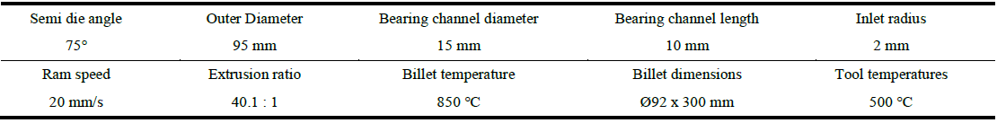
For the validation of the numerical analysis of the extrusion process, extrusion trials were carried out on an 8MN extrusion press with a direct extrusion setup. The extrusion forces were recorded with integrated load cells and the conical dies were fitted with thermocouples in the bearing channel to measure the strand exit temperature. The dies were designed according to literature and feedback from industry [1]. Die dimensions and extrusion parameters are listed in Table 1. The tools made of 1.2367, CS1 and 2.4668 were machined from bulk material. For the use of 2.4775 as extrusion die, an insert (Ø60 x 20 mm) was shrink fit into a holder made of 1.2367, since the cobalt-based alloy is prone to cracking due to low toughness.
Table 1. Die dimensions and extrusion parameters
3 Results and Discussion
3.1 Hot Compression Tests
Excerpts from the flow stress data of the copper alloy CW024A obtained by hot compression tests are shown in Figure 1. The flow stress decreases with increasing temperatures and strain rate sensitivity is low. The stress offset at a true strain of 0 is an artifact resulting from temperature and strain rate corrections, necessary at strain rates of 1 s-1 or higher.
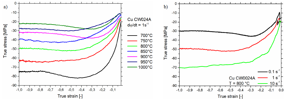 Figure 1. True stress-true strain curves of copper CW024A: (a) at a constant strain rate of 1 s-1 and (b) at a constant temperature of 800 °C
At a true strain of 0.9 and higher, the flow stress is assumed constant. Therefore, the flow stress values at a true strain of 1 were used to model the visco-plastic behavior using the constitutive sinh-Arrhenius equation [7]

where R is the gas constant, Z is the Zener-Hollomon parameter, Q is the activation energy and A, α and n are material constants. Following the procedure presented in [8] and performing a minimization of error squares the material constants were determined (Table 2).
Table 2. Material constants for the constitutive sinh-Arrhenius equation

The true stresses of the experimental data at a true strain of 1 are compared to the stresses predicted by the constitutive model in Figure 2. The graph depicts a very high degree of agreement for the whole tested temperature range (700-1000°C) and strain rate range (0.1-10 s-1). Furthermore, the stresses, extrapolated by using the constitutive model, for very low and very high strain rates of 0.01 s-1 and 100 s-1, respectively, are shown.
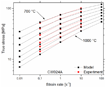 Figure 2. Comparison of experimental and modeled flow stress data
The flow stress data of the tool materials, necessary for the modeling of the deformation behavior, is presented in Figure 3. The hot-work tool steels 1.2367 and CS1 differ in flow stress only at temperatures between 500-650 °C, where the CS1 is of higher strength. Both steels show a rapid decrease of strength starting at temperatures of 550 °C until a flow stress of approximately 200 MPa is reached at 800 °C. In comparison, the nickel-based alloy 718 features only a strength comparable to that of 1.2367, but only loses significant strength at temperatures of 750 °C or higher. The cobalt-based alloy 2.4775 reveals high strength but low ductility in a temperature range from 500-700 °C, where brittle fracture of the specimen caused an early abort of the hot compression test. At higher temperatures the strength decreases to the advantage of ductility, but still outperforms the 2.4886. In terms of high temperature application during hot extrusion of copper, the nickel- and cobalt based alloys show the best requirements for low tool deformation [9].
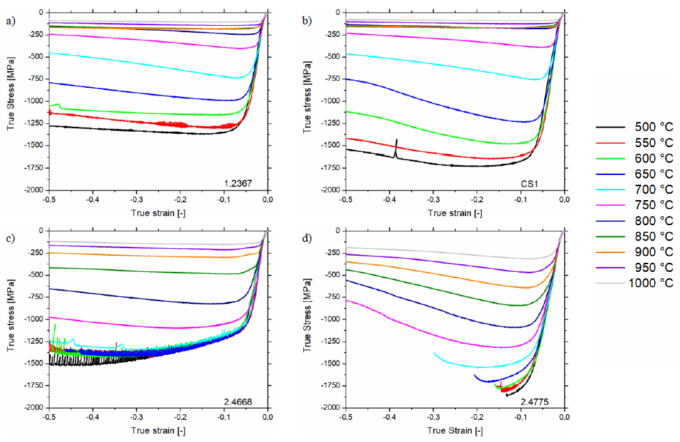 Figure 3. True stress-true strain curves of (a) hot-work tool steel 1.2367, (b) special hot-work tool steel CS1, (c) nickel-based alloy 2.4668 and (d) cobalt-based alloy 2.4775 at a strain rate of 0,005 s-1
3.2 Extrusion Trials
The extrusion diagrams of the four extrusion trials, performed with dies of the same geometry but different tool material, are shown in Figure 4. Since the tool material has no significant influence on the extrusion forces, only little variation can be observed in these. The course of die and friction force is typical for high temperature direct extrusion. Due to heat dissipation from the billet into the container the billet temperature decreases and the flow stress increases. This causes an increase of die force. For the friction force the steady decrease can be explained by the reduction of friction area with progression of the extrusion [1].
The measurements of the strand exit temperature vary in the range of 475-800 °C. Since the billet temperature was 850 °C in every trial, a low temperature of 475 °C, as observed in the trial with 2.4668, indicates a measurement error. A faulty thermocouple is probably the cause for the incorrect measurement. In case of the trials with 1.2367 and CS1, most likely, the fixation of the thermocouple was insufficient and the tip of the thermocouple was pushed back into the die, thus measuring the bulk temperature.
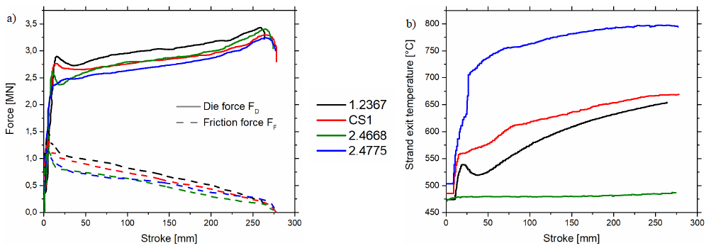 Figure 4. Extrusion diagrams: (a) extrusion forces and (b) strand exit temperatures
3.3 Numerical Analysis of High Temperature Copper Extrusion
The numerical analysis of the high temperature extrusion process was performed with the FE-software DEFORM 2D. The geometrical model and mesh of the simulation are illustrated in Figure 5. The mesh was made of rectangular elements, which size was defined by mesh windows to facilitate fine mesh and therefore high resolution in areas with severe deformation of the billet. That is an absolute element size of 4 mm in the bulk area of the billet, 1 mm and 0.3 mm at the contact surfaces with container and die, respectively. Temperatures of billet and tools were set to 850 °C and 500 °C, respectively, and ram speed was programmed as function of stroke to reproduce the inertia of the extrusion press during the beginning of the extrusion.
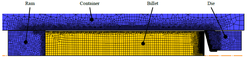 Figure 5. FE-model of the direct extrusion setup
The visco-plastic deformation behavior of copper was modeled using the material model described in paragraph 3.1. For the analysis of the extrusion process all tools were defined as rigid objects and a heat transfer coefficient of 8 kWm-2K-1 was set for all contact surfaces. The defined friction parameters are listed in Table 3.
Table 3. Friction parameters for the numerical analysis of the extrusion process

In Figure 6, the forces and temperatures estimated by the simulation are compared with the experimental data. Considering the excellent reproducibility of the force curves in the experiment, an average of the four trials was calculated and used for the validation of the numerical analysis. While the die forces are in exact agreement, small deviation in friction force can be seen at a stroke of 5-10 mm. Since the material model used is strain-independent, the peak in flow stress at low strains is not represented and the peak in friction force cannot be reproduced. For comparison of the strand exit temperature, the temperature of billet and die was tracked 0.2 mm below the surface at the position of the thermocouple. The estimated strand exit temperature is characterized by a peak of 875 °C at a stroke of 20 mm and a linear decrease until the end of the extrusion process. This represents the expected progression during high temperature extrusion [1]. In contrast, the measured strand exit temperature of the trial with 2.4775 as die material agrees very well with the die temperature. This supports the theory of a displaced thermocouple and the measurement of the dies bulk temperature. Regardless of this, simulation and experiment are in very good agreement and the data obtained by the simulation can be used to perform a decoupled stress analysis of the die.
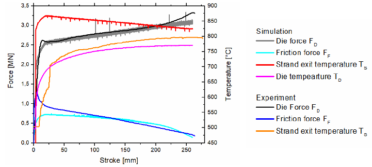 Figure 6. Extrusion diagram of experiment and numerical analysis
3.4 Decoupled Die Stress Analysis
In order to gain information about die deflection and deformation, decoupled die stress analyses were carried out. The elasto-plastic material behavior of the tool materials was modeled by implementing the flow stress data, obtained by hot compression tests, in Deform in tabular form. The thermo-mechanical load during the extrusion process was reproduced by interpolation of temperature and load from the extrusion analysis. Due to the maximal thermo-mechanical load at the end of the extrusion process, state variables were interpolated from the last step of the numerical analysis. Since the thermal properties of all four tool materials are very similar, the same temperature distribution was assumed for all of them (Figure 7). To emulate multiple extrusion cycles, the mechanical load was alternately applied and released.
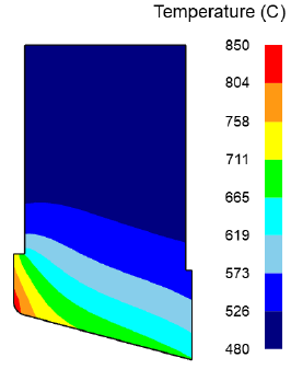 Figure 7. Temperature distribution in the die interpolated for the die stress analysis
The evolution of strain in the die over three load cycles is exemplary shown for the die made of 1.2367 in Figure 8. Cycle 0.5 represents the first loaded state with a peak strain of 0.007 at the inlet radius. After releasing the load (cycle 1), the strain returns to approximately zero, with exception of the area in proximity to the inlet radius. The remaining strain of 0.004 indicates plastic deformation due to exceedance of the yield strength. With further load cycles, the remaining strain and thus the plastic deformation increases to 0.008.
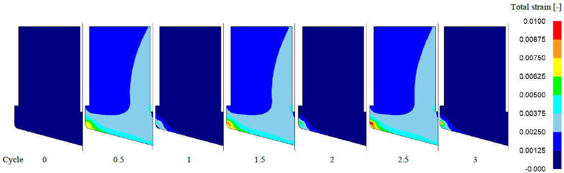 Figure 8. Strain evolution in the die made of 1.2367 over three load cycles
Figure 9 and Figure 10 illustrate the distribution of plastic strain after three load cycles. For the die made of 1.2367 (Figure 9a) a large field of plastic strain with values up to 0.008 is visible at the inlet radius. Figure 9b reveals a field of strain with similar extent but larger values of up to 0.016 for the die made of CS1. Considering the flow stress data of both materials (see Figure 3), this is due to the lower compressive yield strength of CS1 at temperatures above 750°C. As a result of the great high-temperature strength of the nickel- and cobalt-based alloys, the dies made of these materials show overall lower plastic strain values as low as 0.003 and 0.001, respectively (Figure 10a and Figure 10b). High plastic strain is only observed at the conical surface of the holder made of 1.2367.
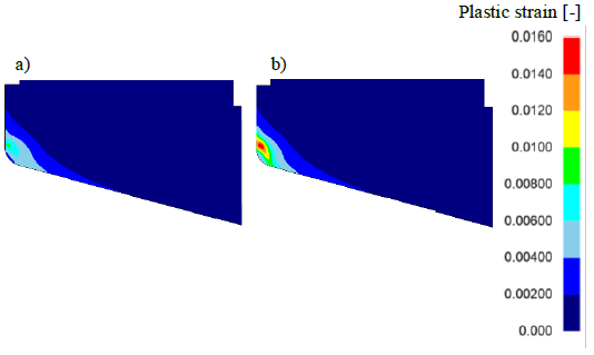 Figure 9. Plastic strain after three load cycles in the die made of (a) 1.2367 and (b) CS1
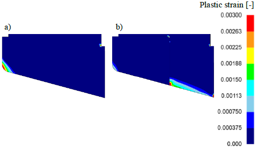 Figure 10. Plastic strain after three load cycles in the die made of (a) 2.4668 and (b) 2.4775
Due to the plastic deformation in proximity of the inlet radius, the geometry of the bearing channel is altered. This is highly undesirable, as the product quality of the extruded rods is lowered by geometrical deviations. The deformation of the dies is visualized in Figure 11 by plotting the radial displacement of the dies functional surface. Measurements were taken at 150 equidistant points along the contour line shown in Figure 11a, starting at the end of the bearing channel and ending at the outer edge of the die cone. For the die made of 1.2367 an overall displacement in positive R direction can be seen in Figure 11b. The reason for this is a small degree of plastic deformation on the surface of the die cone. The increasing plastic deformation of 1.2367 over consecutive load cycles is expressed by the gradual displacement of the points at a contour length of approx. 11 mm (Figure 11b). This contour length represents the inlet radius, where the die cone transitions into the bearing channel. As a result of high thermo-mechanical stress, namely maximal die temperature and high stress on the die cone, the tool material is pushed into the bearing channel, which equals a displacement in negative R direction. These plastic deformations, predicted by the numerical analysis, are in agreement with industrial observations, where dies have to be recalibrated after few extrusion cycles [2]. Similar observations are made for CS1 (Figure 11c). However, the radial displacement with consecutive load cycles is almost twice as large due to the aforementioned lower compressive yield strength at temperatures above 750 °C. Compared to 1.2367 the overall displacement in positive R direction at a contour length of 35-54 mm is reduced because of the higher compressive yield strength at temperatures below 750 °C. According to the findings of Schwartz et al. it is necessary to maintain good hardness and high toughness in working condition to avoid tool damage [2]. Looking at the nickel-based alloy 2.4668 (Figure 11d), which meets both of these criteria, the overall displacement in R direction is very low with a small peak at the inlet radius and no changes of displacement are observed with consecutive load cycles. Considering the true stress-true strain curves (see Figure 3c), this can be reasoned by the particularly good high-temperature strength at temperatures up to 700-750 °C. The same applies for the cobalt-based alloy 2.4775 (Figure 11e), which distinguishes itself by an even greater high-temperature strength. The discontinuity at a contour length of 35 mm is due to the transition from the shrink fitted insert to the holder, which is made of the softer 1.2367 and therefore is subject to plastic deformation.
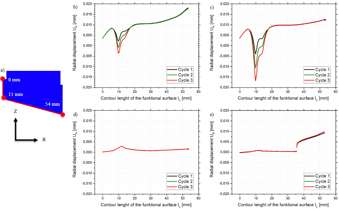 Figure 11. Contour line for measurement of displacement (a) and the evolution of radial displacement over three load cycles for the tools made of (b) hot-work tool steel 1.2367, (c) special hot-work tool steel CS1, (d) nickel-based alloy 2.4668 and (e) cobalt-based alloy 2.4775
4 Summary
In order to analyze the die deflection and plastic die deformation during high temperature copper extrusion, a decoupled stress analysis was performed with the FEM-based software DEFORM 2D. For this purpose, flow stress data of the copper alloy CW024A and four tool materials (hot-work tool steels 1.2367 and CS1, nickel-based alloy 718, cobalt-based alloy Stellite 1) was obtained by hot compression tests using a Gleeble 3800. Prior to the decoupled stress analysis, the extrusion process was modeled and verified by trials. The thereby acquired load and temperature data was utilized to simulate the die deflection and plastic deformation.
Significant plastic deformation was predicted for the special hot-work tool steel CS1 due to the lowest high-temperature strength of the investigated materials, closely followed by the hot-work tool steel 1.2367. Furthermore, the displacement of the functional surface in proximity to the inlet radius increases with additional extrusion cycles for both tool materials. The nickel- and cobalt-based alloys 2.4668 and 2.4775 excel due to their high-temperature strength and only show negligible plastic deformation. An increasing plastic deformation with advancing numbers of extrusion cycles is not predicted. However, the high material cost of the cobalt-based alloy and the need to use a shrink fit configuration must be taken into account, when choosing the tool material for extrusion dies. Considering its moderate cost and excellent material properties under given conditions, the nickel-based alloy is the most suitable for high temperature copper extrusion and the application of boron containing and boridic surface layers among the four materials studied.
Acknowledgements
The authors are grateful for the financial support of the Arbeitsgemeinschaft industrieller Forschungsvereinigungen (AiF) [grant No. 19862 N].
