


- Home
- volume 13 (2009)
- numéro 3
- Hydrodynamic systems for assessing surface fouling, soil adherence and cleaning in laboratory installations


View(s): 6129 (10 ULiège)
Download(s): 198 (1 ULiège)

Hydrodynamic systems for assessing surface fouling, soil adherence and cleaning in laboratory installations

Editor's Notes
Received on October 29, 2008, accepted on March 4, 2009
Résumé
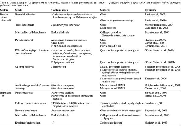
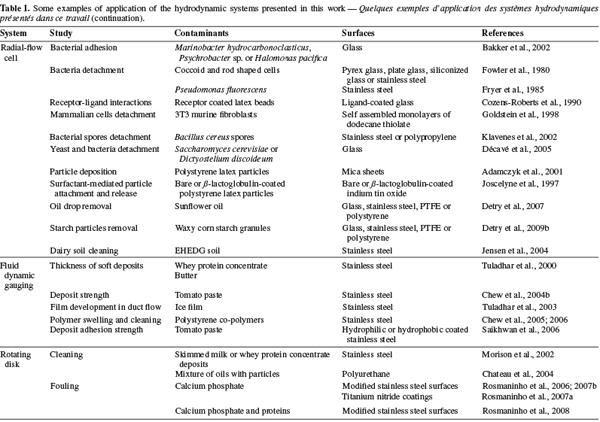
Systèmes hydrodynamiques permettant l’évaluation de l’encrassement des surfaces, de l’adhérence des souillures et de leur nettoyage en laboratoire. Cinq systèmes hydrodynamiques sont présentés dans cette synthèse bibliographique : la cellule à plaques parallèles, le jet impactant, la cellule à flux radial, le disque rotatif et le jaugeage dynamique. Ces systèmes sont particulièrement intéressants pour l’étude de l’encrassement, du nettoyage ou de l’adhésion sur les surfaces solides. Leurs principales propriétés sont données et les principaux avantages et inconvénients pouvant être rencontrés lors de leur mise en œuvre sont présentés. Des exemples de domaines où ces systèmes sont utilisés sont également fournis.
Abstract
Five hydrodynamic systems are presented in this short review: the parallel plate flow cell, the impinging jet, the radial flow cell, the rotating disk and fluid dynamic gauging. These systems are of particular relevance to study surface fouling, surface cleaning or adhesion onto solid surfaces in laboratory environment. The key features of their hydrodynamics are given as well as their practical advantages and drawbacks. Examples of applications fields are also listed.
Table of content
1. Introduction
1The ability of a surface to reduce the adhesion of microorganisms (or other contaminants), to inhibit the formation of deposits or to release the adherent deposits and microorganisms is something essential for a wide field of applications like ship hulls, medical implants, dental enamel, pipelines, surgical instruments, buildings, food and pharmaceutical processing, etc. (Changani et al., 1997; Bakker et al., 2003b; Bansal et al., 2006; Liu et al., 2006). Recently, the modification of surfaces or the elaboration of new coatings has been shown to reduce the attachment of bacteria (Zhao et al., 2005a), the formation of scales (Zhao et al., 2005b; Rosmaninho et al., 2006) or the adherence of food deposits (Saikhwan et al., 2006). Furthermore, the modification of surfaces is attracting considerable attention thanks to the advent of affordable tailored coatings and the capability for applying new surface modification technologies to the scale of equipment parts.
2Assessing the ability of a surface to reduce adhesion or to release contaminants easily is critical to improve the understanding of adhesion mechanisms, to identify the critical surface features influencing it or to compare different surfaces in well-controlled conditions. Furthermore, attempts to relate surface engineering to a given application do not always allow real time and in situ observation in spite of the need to consider environmental variables such as flow (Jensen et al., 2004), heat and mass transfer (Rosmaninho et al., 2007a), passage of an air-liquid interface (Gómez Suárez et al., 2001a), presence of chemicals or surfactants (Joscelyne et al., 1997; Morison et al., 2002; Chateau et al., 2004) etc.
3Flow chambers and other similar hydrodynamics devices reviewed in this work proved to be valuable tools to take those environmental variables into consideration while allowing easy observation, easy set-up as well as standardization and comparisons between laboratories. Their simple geometry allows the generation of well-controlled, reproducible flow conditions for which the analytical solutions of the Navier-Stokes equations and the convective diffusion equation are often available (Elimelech, 1994). Most of them are also easy to design and can be used as modules to constitute test rigs together with a pump, a heating device, measuring devices, etc. They can also be adapted to various sizes of samples as long as similarity is preserved, depending on the representativeness of the studied surfaces and on cost or technological limitations.
2. The parallel plate flow cell
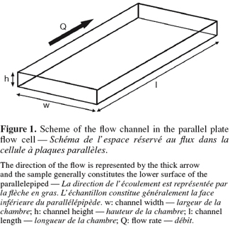
4The test part of the parallel plate flow cell or parallel plate flow chamber is constituted of a bottom plate and an upper plate (one of the two or both being the sample surface) separated by a distance h and forming a rectangular flow channel of width w (Figure 1). It is generally used to generate a laminar shearing Poiseuille flow parallel to the sample surface though its adaptation to generate fully-developed turbulent flow conditions was also reported to expose the samples to the hydrodynamic conditions encountered at the surface of ship hulls (Schultz et al., 2000; 2003).
5The flow regime in the test section can be deduced from the Reynolds number, which depends on the properties of the fluid, the flow rate and the dimensions of the flow cell. The Reynolds number in this flow channel is given by (Bakker et al., 2003b):
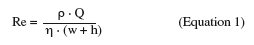
6where ρ is the density of the fluid (kg.m-3), Q is the volumetric flow rate (m³.s-1), η the dynamic viscosity (kg.m-1.s-1), w the width of the flow channel (m), h the separating distance between the upper and the lower plate (m).
7Two-dimensional steady and laminar flow can be assumed for Re ≤ 2000 (Bos et al., 1999). However, whatever the design of the system, fully developed laminar unidirectional Poiseuille flow will only be established at a certain distance from the inlet of the rectangular test section. This distance is called the establishment length, Le (in m). To reduce the establishment length, the inlet should be followed by a gradual expansion (diffuser) before the flow channel and in line with it. The outlet should be preceded by a similar gradual contraction in line with the flow channel (Bakker et al., 2003b). In addition, the dimensions of the flow channel, the flow rate and the nature of the fluid will influence the value of Le (Lorthois et al., 2001; Mercier-Bonin et al., 2004; Busscher et al., 2006):
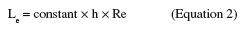
8The value of the constant varies from 0.013 (Busscher et al., 2006) to 0.273 (Lorthois et al., 2001) depending on the flow cell design. After this length, the flow can be considered as fully developed and the shear rate at the surface of the sample (, in s-1) can be considered constant throughout the whole test section. This shear rate is given by (Bakker et al., 2003b):
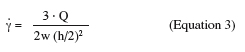
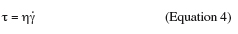
9This expression defines the velocity gradient perpendicular to the wall. For Newtonian fluids like water, multiplying the wall shear rate by the dynamic viscosity of the fluid gives the wall shear stress which is the hydrodynamic force per unit surface area exposed to the flow. The wall shear stress (τ, in N.m-2) is parallel to the wall and is expressed by:
10The multiplication of the shear stress by the area of the adhering soil, microorganism or particle exposed to the flow would give the hydrodynamic drag force exerted on it (Busscher et al., 2006).
11For bacteria, application of successive periods of low and high shear stress was also recently performed for the determination of a “critical wall shear stress” with the parallel plate flow cell. A bacterial suspension is circulated at low wall shear stress for 30 min followed by removal periods of 30 min at increasing wall shear stress. The critical wall shear stress is the wall shear stress at which bacterial attachment and detachment balance each other or, in other words, when the change in number of adhering bacteria was stabilized to zero after application of the higher shear stress. A critical force reflecting the adhesion strength of the bacteria can then be deduced from this shear stress values (Nejadnik et al., 2008).
12In the case of a single spherical particle, the flow around the particle is purely viscous when Rep << 1. In the case of a rigid spherical particle in contact with a wall and exposed to slow linear shear flow, the particle will be exposed to hydrodynamic drag (FD), torque (M) and lift (FL) which can be related to the wall shear stress according to (Brooks et al., 1996; Mercier-Bonin et al., 2004):
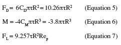
13where R is the particle radius, CD the drag coefficient and CM the moment coefficient. Lift is generally assumed as negligible in the theory of detachment of particles as long as the flow around the particle is purely viscous. This can be expressed by (Hubbe, 1984):
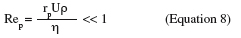
14where Rep is the particle Reynolds number, U is the average flow velocity around the particle (m.s-1) and rp is the particle radius (m). Equations 5 and 6 are valid as long as Equation 8 is satisfied and the relation between the hydrodynamic drag force and the wall shear stress can be assumed independent of the flow rate in these conditions and computing the balance of forces on the particle at the moment of detachment will give the strength of adhesion (Cardot et al., 2001; Lorthois et al., 2001; Detry et al., 2009b).
15However, if Rep becomes larger than 0.05, inertial effects are present in the flow close to the particle and cannot be further neglected. This will result in a decrease of the drag and moment coefficients which becomes increasingly significant as Rep increases and in a decreasing proportionality between the wall shear stress and the force exerted on the particle (Hubbe, 1984).
16The main advantage of the parallel plate flow cell is the ability to generate a simple flow of constant wall shear stress along a sample surface. Its geometry and the nature of the flow make it easy to place as a “module” into a closed circuit. Furthermore, the use of a transparent material for the upper wall of the channel allows in situ observation. One of the main drawbacks of the system is its design which lacks of flexibility. Indeed, once the geometry of the system built, it is impossible to change it afterwards. Care should thus be taken to think about the wall shear stress range that it will be possible to generate, about the required Reynolds number and flow rates (pump) and about the dimensions of the samples. As shown by Equations 2, 3 and 4, if high wall shear stresses are required for an application (like the removal of strongly adhering contaminants), the channel height will generally have to be ≤ 200 µm in order to keep with reasonable flow rates and sample sizes (Guillemot et al., 2006). A width-to-height ratio larger than five should be kept in order to exclude side-wall effects (Bos et al., 1999). The reduction of the flow channel height will also have an influence on the size of the contaminants. At low flow rates for instance, an adherent particle should have a diameter ≤ 1/15 h and should be separated from its neighbors by more than five times the particle radius to avoid disturbing the flow and satisfy Equation 8 (Brooks et al., 1996). Another disadvantage of the parallel plate flow cell is that the flow arrives parallel to the sample surface, meaning that, if the sample is placed in a recess, there should be no misalignment between the sample and the flow cell (Schultz et al., 2000). An alternative would be to replace the whole lower plate of the parallel plate flow cell by the sample (Mercier-Bonin et al., 2004) but this would result in bigger sample sizes, which is not always feasible. To conclude, the parallel plate flow cell seems to be more suitable for weak-adherence systems with small and well-separated adhering soils (oil droplets, particles or microorganisms). Some examples of studies realized with the parallel plate flow cell are given in table 1.
3. Impinging flow systems
3.1. The impinging jet
17The impinging jet is a system widely used to study heat and mass transfer for various applications like annealing of metal and plastic sheets, tempering of glass plates, drying of various materials, cooling of heated components in engines, deicing of aircraft systems, etc. (Tu et al., 1996; Yapici et al., 1999). Examples of applications in relation with the detachment of contaminants from solid surfaces are listed in table 1.
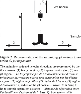
18The system consists in a jet flow of liquid exiting through a nozzle of radius ri, perpendicular to the surface and situated at a distance h from it. A stagnation point is present on the surface where the nozzle axis crosses it. The flow domain of an impinging jet can be divided in three regions for both laminar and turbulent regimes (Deshpande et al., 1982; Yapici et al., 1999):
19– the free jet region where the fluid is not influenced by the surface and where the dominant velocity component is axial;
20– the impingement region where the fluid impacts the surface and where the dominant velocity component changes from axial to radial;
21– the wall jet region in which the dominant velocity is radial. As the radial position taken from the center of the inlet nozzle increases, the radial velocity and thus the wall shear stress both decrease (Figure 2).
22A radial gradient of decreasing wall shear stress is thus generated at the impinged surface. The magnitude of the wall shear stress distribution depends on the nozzle-surface distance h, the nozzle diameter r and the Reynolds number of the fluid in the nozzle. Numerical solutions of the wall shear stress distribution are available for laminar flow (Deshpande et al., 1982; 1983) and turbulent flow (Tu et al., 1996; Yapici et al., 1999; Phares et al., 2000b). In the case of liquid jets, both the studied surface and the nozzle must be immersed. This is obviously not the case when the impinging fluid is air.
23Soiled surfaces can thus be placed perpendicularly from the nozzle at a distance h. The impinging fluid will exert a hydrodynamic force on the adherent soils which will be submitted to a continuous range of shear forces in one experiment. If the hydrodynamic force exerted by the flow exceeds the adhesion force, detachment of the soils will occur near the inlet up to radial positions where the hydrodynamic drag force will be too weak to induce detachment. Then, the nozzle is removed and the radial position up to which removal occurs is measured. This radial position can be converted in wall shear stress with the numerically computed wall shear stress distributions. The wall shear stress associated with removal can then be related to the adhesion force of the soil (Phares et al., 2000a; 2000b).
24The main advantage of the impinging jet is that it allows the adherent soils to be submitted to a continuous range of shear forces in a single experiment with respect to applying a sequence of shear rates using the parallel plate flow chamber. It is also very flexible as the nozzle can normally be adapted to a wide range of sample sizes, as long as this size largely exceeds the nozzle diameter (Bitziou et al., 2006). However, in situ observations are impossible if the substrate is not transparent and if a reverse observation setup (allowing observation from under the jet) cannot be mounted. Another inconvenient of the system may be the need of numerical computation tools to find the wall shear stress which may still be unaffordable for small laboratories. Lastly, the system cannot be easily adapted as a module in a test rig. This inconvenience can however be overcome by confining the jet flow.
3.2. The radial-flow cell
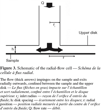
25The radial-flow cell is also known as radial-flow chamber, stagnation-point flow chamber or confined impinging jet. Its use to study biofilm removal was first reported by Fowler et al. (1980). The device consists of two parallel disks with a narrow spacing in-between (typically, the ratio between the disc spacing h and the inlet radius ri is << 1). A fluid is pumped through the center of one disk, impinges on the surface of interest (a stagnation point is present on the surface at the intersection with the inlet axis) and flows radially outward between the disks (Figure 3). As the flow duct cross-sectional area increases with the radius, the linear fluid velocity and hence the shear stress near the surface decrease radially across the disk. As in the case of free impinging jets, the soils adhering to the surface are submitted to a continuous range of shear forces in one experiment. When the soils (typically cells or particles) are submitted to the shear flow and if the mechanical action of the fluid is sufficient, detachment will occur near the inlet (higher shear stress) up to radial positions where only 50% of the soils are detached. If the size distribution of the soils is symmetrical, this radial position is called the critical detachment radius and can be associated to a critical wall shear stress, which is related to the mean adhesion force of the soils (Cozens-Roberts et al., 1990; Lorthois et al., 2001).
26The confinement of the flow allows an easier fluid recovery and eases the close recirculation of the shearing fluid by comparison to conventional jet impingement (Fowler et al., 1980; Jensen et al., 2004). However, in situ observations are again not possible if the sample is not transparent. The system will also be less flexible with respect to the sample size and disc spacing adjustments when included in a closed circuit. Similarly to the parallel plate flow cell, the radial-flow cell seems restricted to small, weakly adherent and well-separated adhering soils (oil droplets, particles or microorganisms) to ensure well-characterized hydrodynamics (Brooks et al., 1996).
27Analytical solutions are available to compute the wall shear stress at the sample surface for creeping flow and fully turbulent flow. The flow regime in the radial-flow cell is characterized by the local Reynolds number across the disk and the Reynolds number in the inlet pipe. Both are respectively given by:
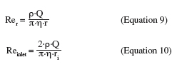
28where r is the radial position (m) and ri the inlet radius (m).
29When the disc spacing is narrow and the Reynolds number low enough, the flow between the discs is laminar. This is generally considered for Reinlet < 2000 (Moller, 1963), even if time periodic or transient unsteady flow structures are reported for inlet Reynolds number varying between 460 and 4,000 at aspect ratios e ≥ 2 (e = h/ri) (Nakabayashi et al., 2002). These instabilities result from inertial effects. They appear above a certain Reynolds number and can lead to the apparition of local 3D flow structures and to the rotation of the global flow pattern around the inlet axis. They tend to disappear when the aspect ratio is reduced (Hsieh et al., 2006). For Reinlet > 4,000, the flow can be considered turbulent in the regions between the discs where the inlet geometry influences the flow (Nakabayashi et al., 2002). At flow rates high enough to produce chaotic flow or even turbulence at low radius, the deceleration of the flow with an increasing distance from the inlet gives a decreasing local Reynolds number and a possible transition to laminar flow (Kreith, 1965).
30Forty years ago, Moller developed analytical solutions to predict the wall shear stress between two parallel disks for both laminar and turbulent ideal diverging flow at any radial position (Moller, 1963):
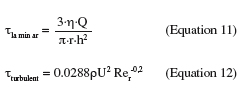
31where U is the mean velocity (m.s-1).
32Fryer et al. (1985) showed that the equation for ideal radial laminar diverging flow (Equation 11) gives a good approximation of wall shear stress only if the inertial forces are small with respect to the viscous forces or, in other words, for radial positions where the effect of the inlet geometry is no longer present. This corresponds to radial positions satisfying (Fryer et al., 1985; Detry et al., 2009a):
33For the other radial positions, Equation 11 is not accurate as a result of the complex hydrodynamics induced by the inlet geometry (Detry et al., 2007) and a number of recirculation zones can be present near the inlet (Goldstein et al., 1997; Chatterjee, 2000; Hsieh et al., 2005; 2006). Then, a numerical solution is needed to compute the critical wall shear stress from the critical detachment radius (Goldstein et al., 1997; 1998; Jensen et al., 2004; Detry et al., 2009a). Examples of applications of the radial-flow cell are given in table 1.
34An interesting alternative to the diverging flow is the use of converging flow, the fluid being sucked into the inlet (Goldstein et al., 1998). In this case, the recirculation zones are present in the inlet pipe and not in the channel where the measurements are performed. Inertial corrections are still needed but the range of shear stresses that can be accurately estimated by Equation 11 for laminar converging flow at an aspect ratio (h/ri) of 0.2 was reported to be more than twice that estimated with diverging flow (Goldstein et al., 1998).
4. Fluid dynamic gauging
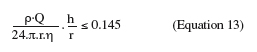
35Basically, fluid dynamic gauging can be compared to the application of converging flow to the free impinging jet system. The technique consists in inducing a flow through a nozzle of diameter dt close and normal to the surface of a deposit (Figure 4). The fluid is sucked from the quasi-stagnant surroundings through a siphon tube. A micrometer controls the vertical position of the nozzle and the distance h between the nozzle and the deposit. If that distance is small (h/dt ∼ 0.25), the flow rate passing through the nozzle will be very sensitive to the spacing between the deposit and the nozzle and the measure of the mass flow rate will allow the computation of the nozzle-deposit distance and hence of the deposit thickness (Tuladhar et al., 2000; Chew et al., 2004a).
36Fluid dynamic gauging thus enables the on-line measurement of the thickness of soft deposit layers (e.g.: whey proteins, tomato paste) adhering to immersed solid surfaces. The build-up of a deposit under defined bulk conditions or the swelling of a deposit during the cleaning process can be measured with this technique. When the shear stress distribution exerted by the flow on the deposit is known, the shearing yield strength of the deposit and its deformation characteristics can be measured as well (Chew et al., 2004b). Several applications of fluid dynamic gauging are presented in table 1.
37This ability to measure on-line the thickness of continuous deposits as well as their mechanical properties is the main advantage of fluid dynamic gauging. Indeed, the technique is very flexible in terms of sample sizes and it can be applied to deposits of any thicknesses. Furthermore, the technique can also be mounted in closed test rigs (Tuladhar et al., 2003; Gu et al., 2007). In situ observation is not easy with this technique but is compensated by the ability of performing on-line monitoring. When the adherence of tomato paste on modified surfaces was studied, significantly different behaviors were observed between the surfaces depending on the deposit-substrate interactions. The adhesive strength of tomato paste deposits was better characterized by the hydrodynamic suction stress normal to the surface than by the wall shear stress (Saikhwan et al., 2006). Though this suction stress is particularly interesting to characterize the deposit properties, it is generally not encountered in real equipment in opposition to wall shear stress, which makes it more difficult to estimate soil adhesion strength and to transfer the data obtained with fluid dynamic gauging to real equipment.
5. The rotating disk
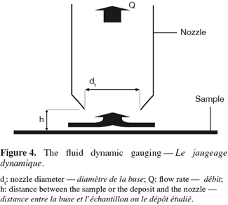
38The rotating disk or spinning disk is a disk that rotates in a fluid at controlled speed. The sample surface is placed on the disk, can be heated or not and is placed in a fouling or in a cleaning solution. In this system, the fluid acquires a rotational motion when it approaches the disk surface. This rotational motion forces it to exit radially (Figure 5). For steady laminar regime, the thicknesses of the hydrodynamic and diffusion boundary layers are constant over the whole surface investigated for a given rotational speed (Elimelech, 1994). Again, the flow regime at the disk surface is given by the Reynolds number (Levich, 1962; Schlichting et al., 2000):
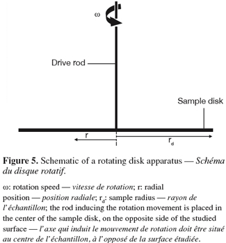
39where rd is the disk radius (m) and ω the rotational speed of the disk (rad.s-1). The regime at the surface of the disk will remain laminar as long as Re < 3 × 10⁵.
40The steadiness of the hydrodynamic and diffusion boundary layers in the laminar regime allows the determination of a well-defined analytical solution to compute the mass transfer to the sample surface (Levich, 1962; Morison et al., 2002):
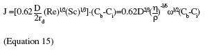
41where J is the mass transfer flux through the boundary layer (kg.m-2.s-1), D is the bulk diffusion coefficient, Re the Reynolds number, Sc the Schmidt number, η the dynamic viscosity of the solution (kg.m-1.s-1), ρ the density of the solution (kg.m-3), Cb the bulk concentration (kg.m-3) and Ci the interfacial concentration (kg.m-3). Methodologies and explanation for the determination of the interfacial concentration can be found in Hunek et al. (2002), Morison et al. (2002) and Rosmaninho et al. (2007a).
42Under these conditions, the wall shear stress at the sample surface varies linearly with the radial position according to (García et al., 1997):
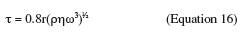
43where τ is the wall shear stress (N.m-2) and r is the radial position (m). In this case, the wall shear stress increases linearly with the radial position conversely to impinging jet flows.
44The major advantage of the rotating disk is the ability to produce a linear range of shear stress at the surface of a sample in a single experiment with uniform chemical conditions over the whole sample surface (García et al., 1997). This characteristic makes of the rotating disk a very interesting tool to study fouling and cleaning although it is not frequently considered for such applications. The system is also flexible with respect to the size of the samples and the height of the deposits but is however difficult to include as module in a test rig. Examples of applications of the rotating disk to surface fouling and cleaning are given in table 1.
6. Application to real equipment
45All above mentioned laboratory systems can be used to generate very useful information required to study cleaning and fouling in controlled conditions. Such information may be the mechanisms of action of a chemical in the breakdown of a soil, the surface parameters influencing the cleaning process, the adhesion strength of a soil to various substrates, the effect of soil ageing on its adherence or the determination of the adequate surface modification that will mitigate fouling, reduce soil adhesion or facilitate soil removal.
46However, the experimental data are generally obtained for planar sample surfaces and, except maybe for wall panels, they cannot be easily applied “as generated” (raw data) to equipment of complex geometry in order to predict how the equipment will be cleaned. This was well illustrated by Jensen et al. (2004; 2005) who tried to relate the critical wall shear stress obtained in a radial-flow cell assay with CFD-computed wall shear stresses to predict the cleanability of a mix-proof valve as a function of wall shear stress only. The study revealed that complex phenomena such as fluid exchange at the vicinity of the surface were influencing soil removal to a non negligible extent and that the critical wall shear stress given by the radial flow cell assay was certainly very useful but not totally satisfactory to predict the cleanability of equipment parts though both cleaning procedures were performed under turbulent flow regime. Indeed, other phenomena associated with flow like wall shear stress oscillations (Lelièvre et al., 2002), pulsating flow (Gillham et al., 2000) and fluid exchange (Jensen, 2003) have been suggested to play a non negligible role in cleaning.
47Furthermore, several problems arise when CFD codes are applied to model cleaning processes. Adequate meshes and turbulence models must be selected because the equipment geometry can be very complex and cleaning is normally performed in the turbulent regime. In this regime, modeling the fluid flow to predict the cleanability of equipment parts requires precise information on the conditions at the walls which differ significantly from the conditions in the bulk (Schlitling, 2000) and wall functions are used to bridge the turbulent flow with the thin viscous layer near the surface. The mesh near the wall must thus be conceived carefully and significant errors may occur depending on the choice of the turbulent model and of the wall function (Casey et al., 2000; Jensen, 2003). Therefore, the numerical results should always be validated with experimental data, which acquisition can be time consuming, difficult to implement or subject to imprecision depending on the technique used (Lelièvre et al., 2002; Jensen et al., 2005; Kipp et al., 2008).
48For these reasons and because modeling can still only give trends on how an equipment will be cleaned (Jensen et al., 2007), the cleanability of closed-equipment conceived to be used on food-processing lines has to be assessed on industrial pilot rigs (Bénézech et al., 2002) with standardized procedures such as the ones developed by the European Hygienic Equipment Design Group (EHEDG, www.ehedg.org) to assess the in-place cleanability of food processing equipment. Several methods already exist and can be used as a basis to compare the cleanability of existing equipment or to assess the hygienic design of new equipment (Hofmann et al., 2006; EHEDG, 2007). The coupling of CFD to the results of the EHEDG test can definitely be used to better understand why certain areas are more difficult to clean and how future equipment should be designed in order to avoid the presence of difficult-to-clean areas (Jensen et al., 2007).
7. Conclusion
49Five different hydrodynamic systems have been reviewed. Each presents advantages and disadvantages. It is impossible to recommend the use of only one of them as their suitability will depend on the application under consideration. For instance, the parallel plate flow cell is well suited for weakly adherent cells, oil drops or particles, in situ observation and for the application of a defined wall shear stress; the radial-flow cell or the impinging jet are more suited for the application of a range of shear forces and for the study of adhesion and adherence in more dynamic conditions (like to study the effect of surfactants on the reduction of the adhesion force of soils); fluid dynamic gauging is particularly adapted to study the formation of continuous deposits, their mechanical properties and their swelling under the action of cleaning chemicals; the rotating disk allows the generation of well-controlled mass transfer conditions to study fouling and cleaning.
50However, as useful as these devices are to better understand the soil-substrate-bulk interactions, their use remains limited to the first phases of research and development. Other tools such as mechanical testing, in situ experiments or modeling are still subsequently needed to complete the information gained with these simple hydrodynamic devices, in order to reach the commercial application of new surfaces or materials.
51Acknowledgements
52This study is part of the researches performed for the SMARTNET project which was supported by the Walloon Region (DGTRE).
Bibliographie
Adamczyk Z., Siwek B., Warszynski P. & Musial E., 2001. Kinetics of particle deposition in the radial impinging-jet cell. J. Colloid Interface Sci., 242, 14-24.
Bakker D.P., Busscher H.J. & van der Mei H.C., 2002. Bacterial deposition in a parallel plate and stagnation point flow chamber. Microbiology, 148, 597-603.
Bakker D.P. et al., 2003a. Bacterial deposition to fluoridated and non-fluoridated polyurethane coatings with different elastic modulus and surface tension in a parallel plate and a stagnation point flow chamber. Colloids Surf. B: Biointerfaces, 32, 179-190.
Bakker D.P. et al., 2003b. Comparison of velocity profiles for different flow chamber designs used in studies of microbial adhesion to surfaces. Appl. Environ. Microbiol., 69(10), 6280-6287.
Bansal B. & Chen X.D., 2006. A critical review of milk fouling in heat exchangers. Compr. Rev. Food Sci. Food Saf., 5, 27-33.
Bayoudh S. et al., 2005. Bacterial detachment from hydrophilic and hydrophobic surfaces using a microjet impingement. Colloids Surf. A: Physicochem. Eng. Aspects, 266, 160-167.
Bénézech T. et al., 2002. A new test method for in-place cleanability of food processing equipment. J. Food Eng., 54, 7-15.
Bitziou E., Rudd N.C., Edwards M.A. & Unwin P.R., 2006. Visualization and modeling of the hydrodynamics of an impinging microjet. Anal. Chem., 78, 1435-1443.
Bos R., van der Mei H.C. & Busscher H.J., 1999. Physico-chemistry of initial microbial adhesive interactions: its mechanisms and methods for study. FEMS Microbiol. Rev., 23, 179-230.
Bouafsoun A. et al., 2006. Evaluation of endothelial cell adherence onto collagen and fibronectin: a comparison between jet impingement and flow chamber techniques. Mater. Sci. Eng. C, 26, 260-266.
Boulangé-Petermann L., Debacq C., Poiret P. & Cromières B., 2003. Effect of the physical chemistry of polymeric coating surfaces on fouling and cleanability with particular reference to the food industry. In: Mittal K.L., ed. Contact angle, wettability and adhesion. Philadelphia, PA, USA: VPS, 501-519.
Boulangé-Petermann L., Gabet C. & Baroux B., 2006. On the respective effect of the surface energy and micro-geometry in cleaning ability of bare and coated steels. Colloids Surf. A: Physicochem. Eng. Aspects, 272, 56-62.
Brooks S.B. & Tozeren A., 1996. Flow past an array of cells that are adherent to the bottom plate of a flow channel. Comput. Fluids, 25(8), 741-757.
Bundy K.J., Harris L.G., Rahn B.A. & Richards R.G., 2001. Measurement of fibroblast and bacterial detachment from biomaterials using jet impingement. Cell Biol. Int., 25(4), 289-307.
Busscher H.J. & van der Mei H.C., 2006. Microbial adhesion in flow displacement systems. Clin. Microbiol. Rev., 19(1), 127-141.
Cardot J., Blond N. & Schmitz P., 2001. Adhesion and removal of particles from surfaces under humidity controlled air stream. J. Adhes., 75, 351-368.
Carman M.L. et al., 2006. Engineered antifouling microtopographies: correlating wettability with cell attachment. Biofouling, 22(1), 11-21.
Casey M. & Wintergerste T., eds., 2000. Best practice guidelines. Special interest group on quality and trust in industrial CFD, Version 1.0. Brussels: ERCOFTAC.
Changani S.D., Belmar-Beiny M.T. & Fryer P.J., 1997. Engineering and chemical factors associated with fouling and cleaning in milk processing. Exp. Therm. Fluid Sci., 14, 392-406.
Chateau M.E., Galet L., Soudais Y. & Fages J., 2004. A new test for cleaning efficiency assessment of cleaners for hard surfaces. J. Surfactants Deterg., 7(4), 355-362.
Chatterjee A., 2000. Newtonian radial entrance flow. AIChE J., 46(3), 462-475.
Chew J.Y.M., Cardoso S.S.S., Paterson W.R. & Wilson D.I., 2004a. CFD studies of dynamic gauging. Chem. Eng. Sci., 59, 3381-3398.
Chew J.Y.M., Paterson W.R. & Wilson D.I., 2004b. Fluid dynamic gauging for measuring the strength of soft deposits. J. Food Eng., 65, 175-187.
Chew J.Y.M., Tonneijk S.J., Paterson W.R. & Wilson D.I., 2005. Mechanisms in the solvent cleaning of emulsion polymerisation reactor surfaces. Ind. Eng. Chem. Res., 44, 4605-4616.
Chew J.Y.M., Tonneijk S.J., Paterson W.R. & Wilson D.I., 2006. Solvent-based cleaning of emulsion polymerization reactors. Chem. Eng. J., 117, 61-69.
Cozens-Roberts C., Quinn J.A. & Lauffenburger A., 1990. Receptor-mediated adhesion phenomena. Model studies with the radial flow detachment assay. Biophys. J., 58, 107-125.
Décavé E. et al., 2005. Biological cell detachment kinetics from an inert substrate. Philos. Mag., 85(26-27), 3173-3189.
Deshpande M.D. & Vaishnav R.N., 1982. Submerged laminar jet impingement on a plane. J. Fluid Mech., 114, 213-236.
Deshpande M.D. & Vaishnav R.N., 1983. Wall stress distribution due to jet impingement. J. Eng. Mech., 109(2), 479-493.
Detry J.G. et al., 2007. Cleanability assessment of model solid surfaces with a radial-flow cell. Colloids Surf. A: Physicochem. Eng. Aspects, 302, 540-548.
Detry J.G., Deroanne C., Sindic M. & Jensen B.B.B., 2009a. Laminar flow in radial flow cell with small aspect ratios: numerical and experimental study. Chem. Eng. Sci., 64, 31-42.
Detry J.G., Jensen B.B.B., Sindic M. & Deroanne C., 2009b. Flow rate dependency of critical wall shear stress in a radial-flow cell. J. Food Eng., 92, 86-99.
EHEDG, 2007. A method for assessing the in-place cleanability of food-processing equipment. Trends Food Sci. Technol., 18, S52-S63.
Elimelech M., 1994. Particle deposition on ideal collectors from dilute flowing suspensions: mathematical formulation, numerical solution, and simulations. Sep. Technol., 4, 186-212.
Fowler H.W. & McKay A.J., 1980. The measurement of microbial adhesion. In: Berkeley R.C.W. et al., eds. Microbial adhesion to surfaces. Chichester, UK: Ellis Horwood Ltd, 141-163.
Fryer P.J., Slater N.K.H. & Duddridge J.E., 1985. Suggestions for the operation of radial flow cells in cell adhesion and biofouling studies. Biotechnol. Bioeng., 27, 434-438.
García A.J., Ducheyne P. & Boettiger D., 1997. Quantification of cell adhesion using a spinning disc device and application to surface-reactive materials. Biomaterials, 18, 1091-1098.
Gillham C.R., Fryer P.J., Hasting A.P.M. & Wilson D.I., 2000. Enhanced cleaning of whey protein soils using pulsed flows. J. Food Eng., 46, 199-209.
Goldstein A.S. & DiMilla P.A., 1997. Application of fluid mechanic and kinetic models to characterize mammalian cell detachment in a radial-flow chamber. Biotechnol. Bioeng., 55(4), 616-629.
Goldstein A.S. & Dimilla P.A., 1998. Comparison of converging and diverging radial flow for measuring cell adhesion. AIChE J., 44(2), 465-473.
Gómez Suárez C., Busscher H.J. & van der Mei H.C., 2001a. Analysis of bacterial detachment from substratum surfaces by the passage of air-liquid interfaces. Appl. Environ. Microbiol., 67(6), 2531-2537.
Gómez Suárez C., Noordmans J., van der Mei H.C. & Busscher H.J., 2001b. Air bubble-induced detachment of polystyrene particles with different sizes from collector surfaces in a parallel plate flow chamber. Colloids Surf. A: Physicochem. Eng. Aspects, 186, 211-219.
Gu T., Chew Y.M.J., Paterson W.R. & Wilson D.I., 2007. Fluid dynamic gauging in duct flows: experiments and CFD simulations. In: Proceedings of the 7th International conference on heat exchanger fouling and cleaning: challenges and opportunities, Tomar, Portugal. Berkeley, CA, USA: The Berkeley Electronic Press.
Guillemot G. et al., 2006. Shear-flow induced detachment of Saccharomyces cerevisiae from stainless steel: influence of yeast and solid surface properties. Colloids Surf. B: Biointerfaces, 49, 126-135.
Hofmann J. & Sommer K., 2006. Hygienic Design von Anlagen und deren Qualifizierungsmethoden. Chem. Ing. Tech., 78(11), 1605-1614.
Hoipkemeier-Wilson L. et al., 2004. Antifouling potential of lubricious, micro-engineered, PDMS elastomers against zoospores of the green fouling alga ulva (Enteromorpha). Biofouling, 20(1), 53-63.
Hsieh J.C. & Lin T.F., 2005. Effects of jet-to-disk separation distance on the characteristics of mixed convective vortex flow in an impinging air jet confined in a cylindrical chamber. Int. J. Heat Mass Transfer, 48, 511-525.
Hsieh F.C., Wu J.H., Hsieh J.C. & Lin T.F., 2006. Unstable vortex flow and new inertia-driven vortex rolls resulting from an air jet impinging onto a confined heated horizontal disk. Int. J. Heat Mass Transfer, 49, 4697-4711.
Hubbe M., 1984. Theory of detachment of colloidal particles from flat surfaces exposed to flow. Colloids Surf., 12, 151-178.
Hunek B. & Cussler E.L., 2002. Mechanisms of photoresist dissolution. AIChE J., 48(4), 661-672.
Jensen B.B.B., 2003. Hygienic design of closed processing equipment by use of computational fluid dynamics. PhD Thesis: Technical University of Denmark, Lyngby (Denmark).
Jensen B.B.B. & Friis A., 2004. Critical wall shear stress for the EHEDG test method. Chem. Eng. Process., 43, 831-840.
Jensen B.B.B. & Friis A., 2005. Predicting the cleanability of mix-proof valves by use of wall shear stress. J. Food Process Eng., 28, 89-106.
Jensen B.B.B., Stenby M. & Nielsen D.F., 2007. Improving the cleaning effect by changing average velocity. Trends Food Sci. Technol., 18, S52-S63.
Joscelyne S. & Trägardh C., 1997. Kinetics of colloidal deposition and release of polystyrene latex particles in the presence of adsorbed b-lactoglobulin studied using a flow cell. J. Colloid Interface Sci., 192, 294-305.
Kipp H., Hellman D.H. & Schlücker E., 2008. Validation of velocity distributions in hygienic designed multistage centrifugal pumps. In: Proceedings of the International rotating equipment conference, Düsseldorf, Germany.
Klavenes A. et al., 2002. Attachment of Bacillus cereus spores with and without appendages to stainless steel surfaces. Trans IChemE, 80(C), 312-318.
Kreith F., 1965. Reverse transition in radial source flow between two parallel planes. Phys. Fluids, 8(6), 1189-1190.
Lelièvre C. et al., 2002. Cleaning in place: effect of local wall shear stress variation on bacterial removal from stainless steel equipment. Chem. Eng. Sci., 57, 1287-1297.
Levich V.G., 1962. Physicochemical hydrodynamics. Englewood Cliffs, NJ, USA: Prentice Hall.
Liu W., Zhang Z. & Fryer P.J., 2006. Identification and modelling of different removal modes in the cleaning of a model food deposit. Chem. Eng. Sci., 61, 7528-7534.
Lorthois S., Schmitz P. & Anglés-Cano E., 2001. Experimental study of fibrin/fibrin-specific molecular interactions using a sphere/plane adhesion model. J. Colloid Interface Sci., 241, 52-62.
Mercier-Bonin M., Ouazzani K., Schmitz P. & Lorthois S., 2004. Study of bioadhesion on a flat plate with a yeast/glass model system. J. Colloid Interface Sci., 271, 342-350.
Moller P.S., 1963. Radial flow without swirl between parallel discs. Aeronautical Q., 14, 163-186.
Morison K.R. & Thorpe R.J., 2002. Spinning disc cleaning of skimmed milk and whey protein deposits. Trans IChemE, 80(C), 319-325.
Nakabayashi K., Ichikawa T. & Morinishi Y., 2002. Size of annular separation bubble around the inlet corner and viscous flow structure between two parallel disks. Exp. Fluids, 32, 425-433.
Nejadnik M.R., van der Mei H.C., Busscher H.J. & Norde W., 2008. Determination of the shear force at the balance between bacterial attachment and detachment in weak-adherence systems, using a flow displacement chamber. Appl. Environ. Microbiol., 74(3), 916-919.
Phares D.J., Smedley G.T. & Flagan R.C., 2000a. Effect of particle size and material properties on aerodynamic resuspension from surfaces. J. Aerosol Sci., 31(11), 1335-1353.
Phares D.J., Smedley G.T. & Flagan R.C., 2000b. The wall shear stress produced by the normal impingement of a jet on a flat surface. J. Fluid Mech., 418, 351-375.
Rosmaninho R. & Melo L.F., 2006. Calcium phosphate deposition from simulated milk ultrafiltrate on different stainless steel-based surfaces. Int. Dairy J., 16, 81-87.
Rosmaninho R. et al., 2007a. Calcium phosphate fouling on TiN-coated stainless steel surfaces: role of ions and particles. Chem. Eng. Sci., 62, 3821-3831.
Rosmaninho R. et al., 2007b. Modified stainless steel surfaces targeted to reduce fouling: evaluation of fouling by milk components. J. Food Eng., 80, 1176-1187.
Rosmaninho R. & Melo L.F., 2008. Protein-calcium phosphate interactions in fouling of modified stainless steel surfaces by simulated milk. Int. Dairy J., 18, 72-80.
Saikhwan P. et al., 2006. Effect of surface treatment on cleaning of a model food soil. Surf. Coatings Technol., 201, 943-951.
Schlichting H. & Gersten K., 2000. Boundary layer theory. 8th edition. Berlin, Heidelberg, Deutschland; New York, USA: Springer-Verlag.
Schultz M.P., Finlay J.A., Callow M.E. & Callow J.A., 2000. A turbulent channel flow apparatus for the determination of the adhesion strangth of microfouling organisms. Biofouling, 15(4), 243-251.
Schultz M.P., Finlay J.A., Callow M.E. & Callow J.A., 2003. Three models to relate detachment of low form fouling at laboratory ship scale. Biofouling, 19, 17-26.
Smedley G.T., Phares D.J. & Flagan R.C., 1999. Entrainment of fine particles from surfaces by gas jets impinging at normal incidence. Exp. Fluids, 26, 324-334.
Thoreau V. et al., 2006. Physico-chemical and dynamic study of oil-drop removal from bare and coated stainless steel surfaces. J. Adhes. Sci. Technol., 20(16), 1819-1831.
Tu C.V. & Wood D.H., 1996. Wall pressure and shear stress measurements beneath an impinging jet. Exp. Therm. Fluid Sci., 13, 364-373.
Tuladhar T.R., Paterson W.R., MacLeod N. & Wilson D.I., 2000. Development of a novel non-contact proximity gauge for thickness measurement of soft deposits and its application in fouling studies. Can. J. Eng., 78, 935-947.
Tuladhar T.R., Paterson W.R. & Wilson D.I., 2003. Dynamic gauging in duct flows. Can. J. Chem. Eng., 81, 279-284.
Vaishnav R.N. et al., 1983. Determination of the local erosion stress of the canine Endothelium using a jet impingement method. J. Biomechanical Eng., 105, 77-83.
Yapici S. et al., 1999. Surface shear stress for a submerged jet impingement using electrochemical technique. J. Appl. Electrochem., 29(2), 185-190.
Zhao Q. et al., 2005a. Development and evaluation of Ni-Cu-P-PTFE composite coatings to minimize microbial adhesion. In: Proceedings of the 6th International conference on heat exchanger fouling and cleaning, Kloster Irsee, Germany. Berkeley, CA, USA: The Berkeley Electronic Press.
Zhao Q. et al., 2005b. Effect of surface free energy on the adhesion of biofouling and crystalline fouling. Chem. Eng. Sci., 60, 4858-4865.
To cite this article
About: Jean G. Detry
Univ. Liege - Gembloux Agro-Bio Tech. Department of Food Technology. Passage des Déportés, 2. B-5030 Gembloux (Belgium). E-mail: detry.j@fsagx.ac.be
About: Claude Deroanne
Univ. Liege - Gembloux Agro-Bio Tech. Department of Food Technology. Passage des Déportés, 2. B-5030 Gembloux (Belgium).
About: Marianne Sindic
Univ. Liege - Gembloux Agro-Bio Tech. Department of Food Technology. Passage des Déportés, 2. B-5030 Gembloux (Belgium).
