1 Introduction
Metal tubes are used in applications such as fluid transportation, casing for cables or as structural elements with high bending stiffness per weight. Tubes and their respective manufacturing processes are separated into the manufacturing of seamless tubes and welded tubes. The manufacturing process of welded tubes starts with sheets which are formed by different processes into components with mainly circular, oval or rectangular cross-sections. The remaining gap after forming is closed by welding along the axis of the tube. Most tubes have a constant cross-section. Different processes exist to modify the cross-section in certain parts of the tube by expansion. The different methods of expansion are, e.g. application of an inner pressure described by Avalle and Scattina [1], mechanical insertion of a conical tool as reported by Fischer et al. [2] or a more complex mechanical tooling set-up with a bottom plate as discussed by Zhu et al. [3]. The term ‘flaring’ is sometimes used to refer to modifications of the shape of the edges of a tube. While the mentioned papers focus on axis-sysmmetric tubular shapes, the current contribution deals with the manufacturing of non-symmetric ovals. Muschik [4] investigated the forming of oval tubes, but not the expansion of the edges. Fischer et al. [2] developed and applied analytical approaches to predict the stresses in the flared flange as well as the load-displacement curve of the conical punch. However, one important aspect, the geometry of the expanded flange depends on the springback after removal of the tools has not been covered. In the expansion of the edges of non-circular tubes, segmented tools produce the final shape, making it difficult to apply analytical approaches. The aim of this paper is to apply finite-element (FE) simulations to analyze expansion processes of non-circular tubes. This provides the opportunity to compensate springback and understand which processes contribute most to the springback.
1.1 Industrial motivation
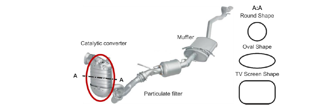
Fig. 1. Sketch of principal set-up of an exhaust system for an automobile with a combustion engine
In the current contribution, the focus is on the expansion processes of tubular components for catalytic converters. The expansion process aims to produce a straight section of the circular or oval tube with a larger inner radius Re at the left and right outer end of the tube (Fig. 2). One or more counter-dies may be brought into contact with the outer tube radius to achieve this shape. Differing form the investigated process of Fischer et al. [2], there are two transition zones, where the curvature of the tube changes.
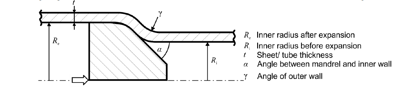
Fig. 2. Simulation results of the last forming step for a deviation of the furnace temperature.
2 Tube forming process
The industrial process chain to manufacture a catalytic converter from an initially plane sheet consists of: (i) trimming rectangular sheets from a coil or larger blanks, (ii) roll-bending and subsequent welding to obtain circular tubes with approximately the required length, (iii) a pre-forming step to produce an oval cross-section from the circular tube, a calibration step to set the target geometry in the inner straight section of the tube and (iv) so-called end-forming to expand the edges (Fig. 3). These mainly forming-based processes are followed by the stuffing process, which inserts the ceramic catalytic component called the monolith into the tube. The monolith is surrounded by a mat, which on the one hand seals the gap between monolith and tube and on the other hand prevents direct contact of the tube and the monolith. The focus of the current investigation are the forming steps (highlighted in gray in Fig. 3), in particular the endforming. Muschik’s analysis targeted to set the appropriate gap between tube and mat.
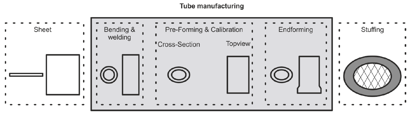
Fig. 3. Industrial process chain to manufacture catalytic converters from initially plane sheet
2.1 Calibration process
In the calibration process (Fig. 4a and Fig 5) a mandrel termed cathedral with a polygonal cross-section is pushed into a number of expansion segments. These segments experience a radial displacement, which increases with increasing axial movement of the rod and the cathedral until the desired position is reached. In the calibration process, the tube is expanded along its complete length. In the case an oval cross-section is formed, three radii (Fig. 4b) describe the geometries. For analysis and measurement purposes the labels ‘Short axis’, ‘Long axis’ and ‘Diagonal axis’ are introduced. These labels are also used in the endforming process. The geometries possess two axes of symmetry.
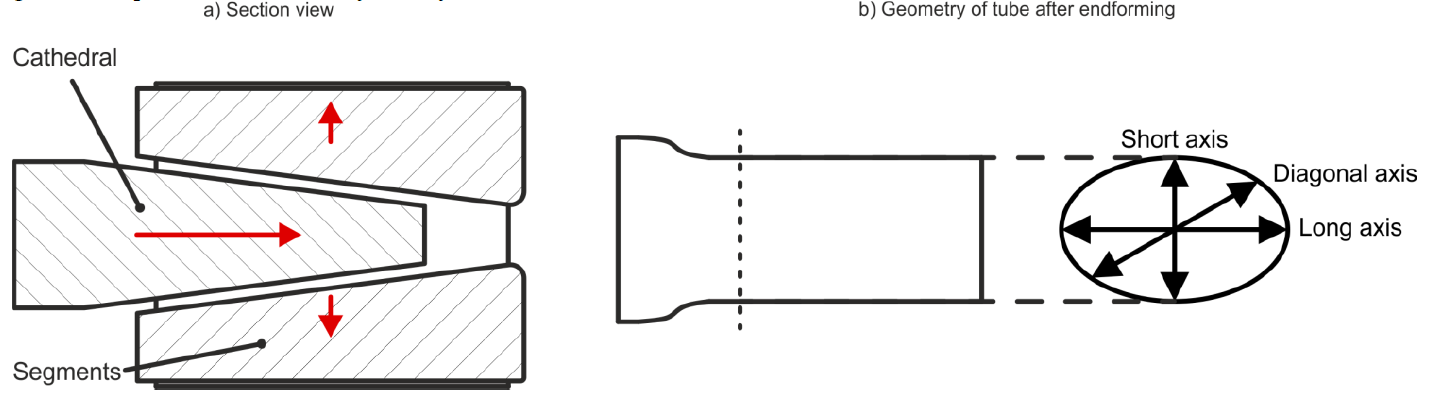
Fig. 4 Calibration tooling and nomenclature for axes labeling (a) Showing the reference process at 1000°C, (b) the reduced furnace temperature at 990°C and (c) the retrieved temperature level by adjusting the impact
2.2 Endforming process
The endforming creates a straight region of the tube at either end of the tube with a larger cross-section. Similar tooling with an even number of radial segments produces the endformed region (Fig. 5). Differing from the calibration process, a counter die ring is inserted to obtain a straight region at the end. Usually, both ends of a tube are formed in subsequent operations with the same tooling. Because of the geometrical symmetry, the analysis is restricted to one side.
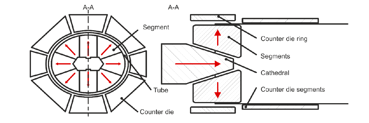
Fig. 5 Calibration tooling and nomenclature for axes labeling
2.3 Material
During operation of an automobile the hot and corrosive exhaust gases flow through the exhaust system. Therefore, tubular components in the exhaust system are manufactured from stainless steels due to their corrosion protection. In the current study circular tubes are produced from stainless steel 1.4509 (EN 10088-2) sheets. Uniaxial tension tests according to DIN 6892 are conducted on Zwick 250 universal testing machine at room temperature to obtain engineering stress-strain curves from the as-received sheet of thickness 1.5 mm, the pre-formed tube, a calibrated tube and a tube after endforming to assess the influence of the forming operations on the material behavior. The specimen are laser-cut. The specimens cut out of the tubes are taken with the gauge length of 80 mm parallel to the axial direction. The specimens are extracted from the side of the tube directly opposite to the weld seam.
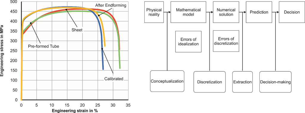
Fig. 6. a) Results of uniaxial tension test (DIN 6892) with specimen shape A80 and b) Scheme for setting up, verifying and validating simulations [5]
The difference between the pre-formed tube and the as-received sheet is small (Fig. 6a), i.e. the difference between the initial yield stresses is smaller than 5% and the difference between the tensile strength is smaller than 4%. The difference between the stress-strain curve of the specimens from the tube after calibration and endforming is very small (< 0.5% in stress). However, the specimens taken from the calibrated or endformed tube exhibit a considerable larger (approx. 20%) initial yield stress compared to the as-received sheet. Interestingly, the tensile strengths of the as-received sheet and the endformed are within 2% flow stress difference. This is attributed to the fact, that a considerable amount of the formability of the material has been consumed in the processes before the tensile test. The additional uniform strain experienced in the uniaxial tension test is 16 % and 24 % for the endformed tube and the as-received sheet, respectively.
3 Simulation, experiments and validation
The simulation strategy aims to predict the geometry of the edges after endforming within the scatter of the experimental results. A deviation of the mean or median value for the position of the tube at the long axis, short axis and diagonal axis of 0.5 mm for equivalent tube radii is acceptable. The equivalent tube radius req = ct /(2π) , where ct is the circumference of the tube. The focus lies on the correct prediction of the geometry at the edges because this is the region, where the tube is joined with other components. The verification and validation approach (see Fig. 6b) follows the strategy outlined by Szabo and Babuska [5].The strategy includes performing the validation for a less complex geometry (circular) and then performing prediction for more complex geometries (oval). An FE-simulation is suited for decision making after validation. Validation describes “the process of ascertaining that it is suitable for the purpose of the simulation by comparison with the physical reality”. Simulation models need to be verified before validation, i.e. it has to be checked that the numerical implementation and solution agree with the mathematical model and its analytical solution. The commercial software AutoForm TubeXpert is chosen for this study. TubeXpert is a special purpose FE program for the simulation of tube forming processes [6]. It is based on the AutoForm code and solver, which uses implicit global time integration to solve quasi-static forming problems. The spatial discretization applies non-linear shells for all deformable bodies. All tools are considered to be rigid. AutoForm recommendations for the mesh size (approx. 0.5 mm edge length in the endforming zone) are used. The springback process is simulated in separate simulation steps after each forming step. The verification process included comparisons with the general purpose programs Abaqus Standard and Abaqus Explicit applying a number of different choices for modelling, e.g. hexahedral elements, different contact formulations, etc. TubeXpert was chosen due to the considerable lower (factors 10 to 100) computing and pre-processing (approx. factor 10) times with deviations between the predicted geometries within the described aims.
One of the hypotheses of the idealization is that it is sufficient to consider calibration and endforming steps because the plastic deformation in the previous steps is small. It is further assumed that the material behavior and the stress state is not affected by the previous forming operations. These assumptions are counter-intuitive from a general metal forming background because one would expect that the differences in the hardening behavior seen in the uniaxial tension tests would influence the forming behavior. Consistent with these assumptions, the material behavior is modeled with an elasti-plastic Hill ’48 model using a yield curve obtained from the uniaxial tension test of the sheet.
3.1 Validation for circular tubes
The outer tube diameter before calibration was 162.9 mm. A circular cross-section with an outer tube diameter of 166.6 mm after the calibration process respectively is chosen. The initial wall thickness is 1.2 mm. The idea is to validate the simulations for a less complex geometry and then to increase complexity. The initial length of the tube is 152.9 mm. Experiments with three repetitions are conducted with the calibration tooling (cf. Fig. 4a). No additional lubrication is applied on the sheets and the subsequently formed tube. The tooling set for both operations consists of 8 segments, which are displaced radially. The geometry of the formed tube is measured with a laser scanner, which uses a laser triangulation technique to determine the outer contour in terms of tabulated x-y data for pre-defined levels along the axial direction of the tube. Cross-sections at 5 different levels were measured. The deviations between different levels were smaller than 0.1 mm. Results of the calibration process are shown for a distance of 85 mm from the edge. After the measurement, the calibrated circular tubes are subjected to endforming with a target outer diameter of 168.8 mm. Contours of the cross-sections were measured at the same distances form the edge for endforming as for calibration. There is only very little springback (0.1 mm) observed. This is attributed to the circular shape, which provides for a uniform deformation along the circumference. The maximum nominal strain, i.e. the increase in circumference divided by the original circumference is smaller than 3.6%.
3.2 Results of validation
The radial deviations of the contours for calibration and endforming are small (< 0.1 mm). Scatter between single experiments and different cross-sections is also in this range. Single points were observed in the entire measuring campaign, which deviate moderately from this, i.e. the deviations were < 0.15 mm. The conducted simulations agreed very well with the measured geometries. The deviation of the predicted cross-sections and the measured cross-sections in terms of the radial distance was smaller than 0.1 mm for calibration and endforming for the investigated cross-sections. This means that the acceptance criteria for the chosen modelling approach are met.
4 Results for oval shape
A tube with increased complexity is considered due to the successful validation of the chosen simulation approach. The nominal diameters of the short and long axes are 144.2 mm and 180.2 mm. The measured geometry is compared with the nominal geometry in the endformed region (Fig. 7). The results show 5 repetitions for the left side and 3 repetitions for the right side.
The measured sections have a distance of 3 mm from the left and right edges.
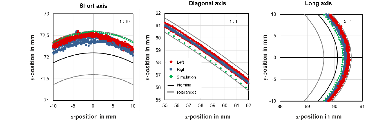
Fig. 7. Comparison of measured geometry (left/right side) and simulation prediction for the endformed region of an oval component. The right upper corners show the aspect ratio of the axes
Due to springback the short axes are between 0.1 to 0.4 mm larger than the target geometry. The long axes are between 0.2 and 0.5 mm larger than the desired geometry. The deviations from the target geometry are smaller than 0.2 mm in the vicinity of the diagonal axes. Therefore, the parts are within the specified tolerances. The geometry predicted by the simulation agrees with the experiments, which barely meet the tolerances at the short axes. The simulations agrees with those experimental parts, which represent the smallest diameters for the large axis. Near the diagonal axis the radius predicted by the simulation is approx. 0.2 mm smaller than the median of the experiments. At first glance, the good agreement of the simulations with the experiments surprises because not all process steps were considered and hardening as well as residual stresses from those were neglected. A more detailed analysis reveals that the maximum plastic strain occurs only in very small regions. The maxima are located in the transition region from the straight inner tube section to the endformed region. The segmented design of the tooling leads to local maxima of the plastic strain and the corresponding stresses in the gaps between the segments. A uniform circumferential stretch is achieved in those regions where the segments were in direct contact with the tube. Apparently, the springback is overestimated for the short axis and the diagonal axes.
5 Outlook
The further work aims at the investigation of further geometries like TV Screen Shape
Acknowledgements
TC, FG, DK, MS are thankful for the support of Faurecia Emissions Control Technologies Germany GmbH within the Research Center in Metals Processing (ReCIMP). The authors thank Uwe Beckmann from AutoForm Engineering Deutschland GmbH for the continuous support of this study.
