1.1 Introduction
In the world of engineering, the prediction of failure plays an important role when it comes to material modeling. Several methods [1] for the modeling of failure have been developed in the last decades depending on the material, geometry, scale, etc. For instance, to model the failure within the bulk, sophisticated advanced damage models based on continuum damage mechanics [2,3,4] are of significance while cohesive zone models [5] mainly address failure at the interfaces.
On the one hand, cohesive zone models are a simple tool to model failure at the interfaces. On the other hand, the simulation results based on CZ models usually agree well with experimental findings [6]. The embedment of CZ models into standard conforming finite elements usually results in some restrictions at the interface. These can be the occurrence of the initial elastic regime prior to failure as in intrinsic CZ models or the necessity of re-meshing of the structure during the crack propagation as in extrinsic approaches [7]. In addition, extra effort has to be made to include hanging nodes in nonmatching meshes [8,9]. One possible solution is to utilize the CZ model together with the DG method at the interface as well as in the bulk [10,11].
Discontinuous Galerkin methods are an alternative to standard continuous Galerkin (CG) methods, in which the continuity of the displacements and tractions are usually only weakly satisfied. Due to various formulations of the DG methods [12], they have found different applications from fluid [13] to solid mechanics [14]. Recently, there has been a growing trend in the application of DG methods in combination with cohesive zone models in fracture mechanics [15,16,17]. One significant motivation of this popularity is the fact that adjacent elements in DG methods do not share mutual nodes in the discretized structure. Consequently, cracks (also known as strong discontinuities) can propagate through the existing inherent weak discontinuities in the DG elements either within the bulk [18] or at the interface [19]. Another advantage of the use of the discontinuous Galerkin method lies in the removal of locking effects [20,21,22,23]. In case of volumetric as well as shear locking problems, DG methods with reduced integration perform remarkably faster than the standard continuous Galerkin element formulations [10,24,25] in terms of mesh convergence rate. A locking-free modeling of the fracture at the interface of brittle materials with non-matching meshes is established in [26].
In the present work, (quasi-) ductile materials [27,28] are taken into account whereas our previous work aimed at the modeling of failure at the interface of brittle materials [26]. To this end, a plasticity model with isotropic hardening is considered for small strain problems using the incomplete interior penalty Galerkin (IIPG) variant of the DG methods [10]. Hanging nodes are incorporated into the discretized model as well. The performance of the cohesive discontinuous Galerkin method in comparison to the standard conforming CZ method is investigated in the problems prompt to volumetric locking as well as including different materials.
The structure of this paper is as follows: First, the strong form of the linear momentum balance is introduced followed by its weak form. Next, the traction separation law (TSL) is given. Afterwards, the elastoplastic model based on the Helmholtz free energy is defined. The corresponding state relations and evolution equations are derived obeying the second principle of thermodynamics. The discretization as well as the numerical integration are given briefly in the framework of the discontinuous Galerkin method. The next chapter is devoted to numerical examples to study the convergence behavior of the CDG method in comparison to that of the conventional models. Finally, conclusions are drawn and possible improvements are suggested.
1.2 Governing equations
1.2.1 Strong form
Starting with the strong form of the problem, the linear momentum balance is given by

Here, 𝝈 is the stress tensor and 𝒇 represents the volume force vector. The boundary conditions are formulated in terms of the prescribed traction vector 𝒕𝑝 and the prescribed displacement vector 𝒖𝑝. The computation of the stresses will follow in 1.2.4. The discontinuity 𝛤 divides the body 𝛺 into subdomains 𝛺𝑒 as illustrated in Fig. 1. We assume 𝜕𝛺𝑢∪𝜕𝛺𝑡=𝜕𝛺 and 𝜕𝛺𝑢∩𝜕𝛺𝑡=∅.
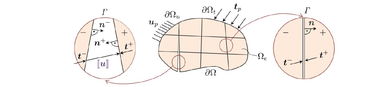
Fig. 1. Body Ω divided by the discontinuity Γ into sub-domains Ω𝑒. Strong discontinuity (left) and weak discontinuity (right)
Due to the presence of discontinuity 𝛤, extra boundary conditions have to be satisfied. In case of weak discontinuities (pre-failure), the displacements and tractions on the inner borders of the subdomains fulfill the continuity conditions in the continuous solution, given by

On the contrary, once the crack propagates (strong discontinuity), displacement jumps ⟦𝒖⟧ are permitted. Nevertheless, tractions remain continuous and are prescribed. In other words,

The operators ⟦⋅⟧=(⋅)+|𝛤 − (⋅)−|𝛤 and {⋅}=1/2[(⋅)+|𝛤 + (⋅)−|𝛤] are the jump and average operators, respectively.
1.2.2 Weak form
The unified weak form of equation (1) considering both weak and strong discontinuities is defined by

where 𝜃=𝜗𝐸/ℎ is the penalty parameter. The positive free parameter 𝜗 is a sufficiently large value, 𝐸 is Young’s modulus and ℎ is the mesh size. The parameter 𝛼 is used to switch between intact (𝛼=0) and damaged interfaces (𝛼=1). In addition, 𝒈 is the gap vector with components in shear (𝑔𝑠) and normal direction (𝑔𝑛) with respect to the discontinuity. In fact, the gap is the displacement jump in a local coordinate system (𝑠,𝑛) and is given by 𝒈=𝑹⟦𝒖⟧. Here, 𝑹 is a rotation matrix. For more details, refer to [26].
1.2.3 Traction separation law (TSL)
Finally, the tractions on the strong discontinuity are calculated by

In the above equation, 𝑡0 is the maximum strength of the interface right before failure, 𝜆=√(〈𝑔𝑛〉2+𝛽2𝑔𝑠2) is the effective separation, 𝜆𝑚𝑎𝑥 is the maximum separation reached so far and 𝜆𝑓 is the separation at full failure (see Fig. 2). To control the contribution of the shear separation, the parameter 𝛽 is defined. Here, 𝑚 is a material parameter to control the convexity of the fading tractions in the traction separation law while 𝑛 is mainly introduced to avoid numerical instabilities during contact. The parameter 𝜃 is the same as that of the DG weak form in equation 4.

Fig. 2. Traction separation law for the extrinsic cohesive discontinuous Galerkin method.
1.2.4 Kinematic assumptions and modeling of plasticity
The kinematics of the problem is specified for elastoplasticity with small strains. As a result, an additive decomposition of the strains follows:

The elastic part of the strain is denoted by 𝜺𝒆=sym (grad (𝒖)) whereas 𝜺𝑝 is the plastic strain. In order to calculate the stresses and the plastic strain, we start with the Helmholtz free energy

It is additively divided into an elastic and plastic part. The elastic part is given by

where 𝕮=𝜆 𝐈⊗𝐈+2 𝜇 𝕴 is the isotropic fourth-order elasticity tensor. Here, 𝜆 and 𝜇 denote the Lamé constants and 𝕴 expresses the fourth-order symmetric identity tensor. The plastic part of the free energy is a function of the accumulated plastic strain 𝜉𝑝. Depending on the type of the hardening rule, this can vary. For instance for the simple case of linear isotropic hardening, the plastic part of the free energy is given by

where 𝐻 is a material parameter.
Applying the second law of thermodynamics −𝜓̇+𝝈⋅𝜺̇≥0, one obtains the relations:

where 𝑞= −𝜕𝜓𝑝/𝜕𝜉𝑝 is the hardening thermodynamical force (driving force). The first relation in equation 10 delivers the stress tensor while the second one is called the residual dissipation inequality. Upon the correct choice of 𝜺̇𝑝 and 𝜉̇̇𝑝, the second law of thermodynamics can be fulfilled. This can be achieved by definition of a suitable yield function, in our case the von Mises yield criterion, which is given by

Here, only the deviatoric part of the stress (𝝈dev) is considered. The isotropic hardening law leads to 𝜎𝑦=𝜎𝑦0−𝑞 and can take different forms depending on the material behavior. In this study we consider either linear hardening 𝑞=−𝐻𝜉𝑝 or the Voce type hardening 𝑞=−𝑄(1−exp(−𝛽𝜉𝑝)). In the former, 𝐻 is the plastic hardening parameter and 𝜎𝑦0 is the initial yield stress. In the latter form, 𝑄 and 𝛽 are material parameters.
Finally, associative plasticity is assumed, leading to the following evolution equations:
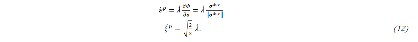
Here, 𝜆̇ is the plastic multiplier. Practically, two cases can occur: either the material is elastic (Φ<0 and 𝜆̇=0) or it is in plastic state (Φ=0 and 𝜆̇≥0). Furthermore, the loading/unloading conditions must be fulfilled, also known as Kuhn-Tucker conditions

1.2.5 Discretization, linearization and numerical integration
Upon the spatial discretization we consider two main types of elements. To discretize the bulk (first integrant of Equation 4), we take the standard four-node quadrilateral elements with polynomials of first order, namely Q1 elements. The discontinuity Γ is discretized by four-node DG elements between the bulk elements or by CDG elements on the interface. In addition, three-node (C)DG elements are placed where hanging nodes appear in the structure. A detailed description of the aforementioned procedures is out of the scope of this work and can be found in [26].
The discretization of the evolution equations (Equation 12) in time is established by means of a fully implicit backward Euler scheme. Within the time interval [𝑡𝑛,𝑡𝑛+1] in a Newton-Raphson iteration at the global level, equation (12) is solved iteratively. In the local plasticity iterations, for a given 𝜀, the quantities 𝜀𝑝, 𝜉𝑝 and Δ𝜆 have to be determined. Here, Δ𝜆=Δ𝑡 𝜆̇ is the plastic multiplier. After solution of the local iterations, the consistent tangent modulus is derived.

Fig. 3. Integration schemes for bulk (Q1) and discontinuous ((C)DG) elements.
The integration of the integrand is carried out numerically by applying the Gaussian quadrature rule. To this end, the bulk element is integrated in a full manner, i.e. using four Gauss points in each element. The terms on the discontinuity are integrated in different schemes. The standard procedure is the full integration besides the nodal integration. However, to eliminate locking effects, reduced integration is applied as in [26]. This is pictured in Fig. 3.
1.3 Numerical examples
This section includes two different examples of elastoplastic structures. The first one is a single-edge notched specimen from [26] with matching meshes. This example aims at the study of the volumetric locking effects and their influence on the crack propagation behavior. The second example is a fiber composite structure from [29]. The debonding between the fiber and the matrix is modeled enabling hanging nodes in the discretized structure.
1.3.1 Single-edge notched specimen
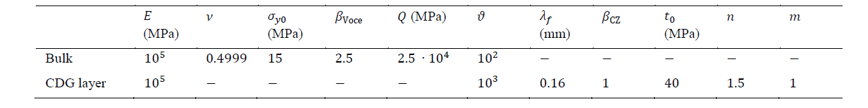
In this example, we examine a plane strain sample with an inherent notch. It is fixed at the bottom and a displacement load is prescribed at its upper edge. Geometry, boundary conditions, loading, discretization as well as the evolution of the plastic zones are illustrated in Fig. 4. Material parameters are given in Table. 1. There is a cohesive layer along the notch, which is discretized by CDG elements. Both the notch and the cohesive layer are of zero thickness. The bulk is discretized by square elements with the same number of elements in each direction for each mesh refinement. The aim is to investigate the convergence behavior of different element formulations for near incompressible elastoplastic materials in the presence of a crack.
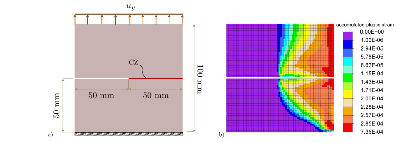
Fig. 4. Single-edge notched specimen. (a) Geometry, boundary conditions and loading, (b) equivalent plastic strain distribution in the discretized form.
Table 1. Material parameters for the notched specimen.
The reaction force-displacement curves for the given example are plotted in Fig. 5. Due to the incompressibility of the material both in elastic and in plastic regimes, volumetric locking effects are observed (see Fig. 5a). Nonetheless, by the use of the reduced integration scheme on the boundary terms, this problem is remarkably diminished. Figure 5b shows that converged results are achieved with almost eight elements in each direction. A better comparison of the convergence rate for the same mesh refinement level (16 elements) is shown in Fig. 5c, where full integration shows overestimated reaction forces and even with 128 elements in each direction, it does not reach the converged solution completely. Finally, in order to illustrate the presence of the plastic strains, the specimen is unloaded at 40% of the total given displacement to its origin and then reloaded thoroughly (refer to Fig. 5d).
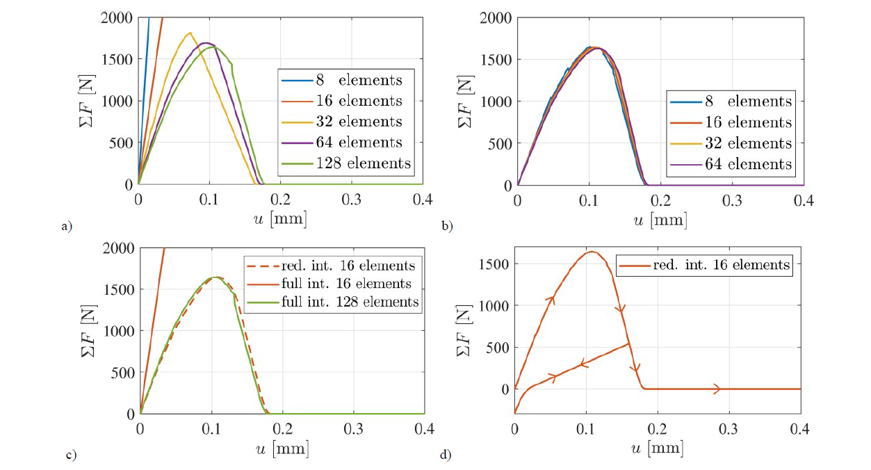
Fig. 5. Single-edge notched specimen. Reaction-force displacement curves for different integration schemes on the discontinuity Γ: (a) full integration, (b) reduced integration, (c) comparison between full and reduced integration. (d) Unloading and reloading of the notched specimen.
1.3.2 Fiber composite structure
A composite structure similar to [29] including a fiber with a circular cross-section surrounded in matrix is studied here. Geometry, boundary conditions and loading of the composite structure are pictured in Fig. 6a for a quarter of the geometry due to its double symmetry conditions. The distribution of the accumulated plastic strains in its discretized form together with the propagation of the crack at the interface of the fiber and matrix are depicted in Fig. 6b. In addition, material parameters for the matrix, fiber and the cohesive layer between these two materials are given in Table. 2. The structure is being pulled apart at its left and right edges through a prescribed displacement. The convergence behavior of the CDG elements in terms of reaction force-displacement curves with and without non-matching meshes is compared to that of a standard continuous intrinsic cohesive zone element formulation [30] with matching meshes (see Fig. 7). The DG elements in the fiber structure are integrated in a reduced manner while the CDG elements can be integrated using different schemes (here: full, reduced and nodal).
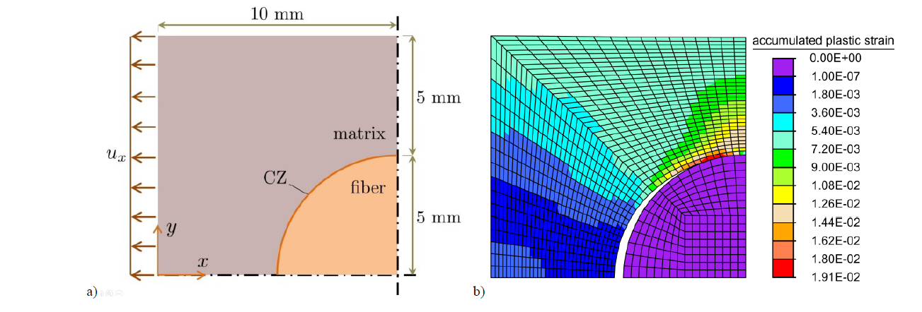
Fig. 6. Fiber composite structure. (a) Geometry, boundary conditions and loading for the quarter of the geometry (b) accumulated plastic strain distribution, discretization and crack propagation (deformations are 5 times magnified).
Table 2. Material parameters for the fiber composite structure.
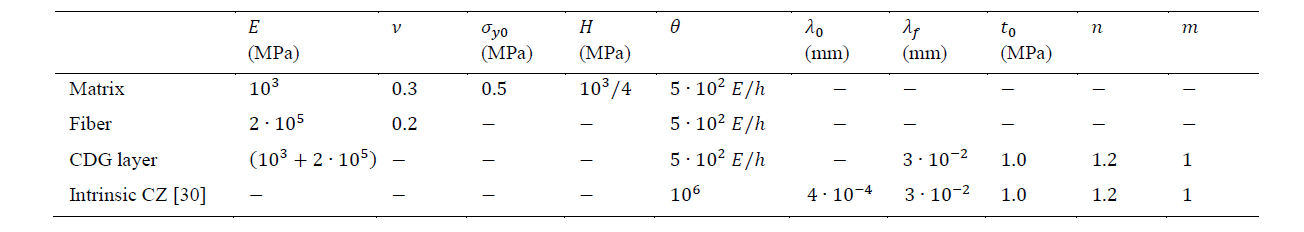
Figure 7a shows that by application of the non-matching meshes, a smaller number of elements is required to capture the same behavior. This is due to the fact that the fiber is 200 times stiffer than the matrix. Thus, it does not require a fine mesh as that of the matrix. The numbers indicate the sum of the elements in each direction for the matrix and the fiber, respectively. Figure 7b illustrates the influence of the hardening isotropic plasticity on the behavior of the bulk as well as the interface for the same given parameters. Having a pure elastic material results in a completely different interface behavior.
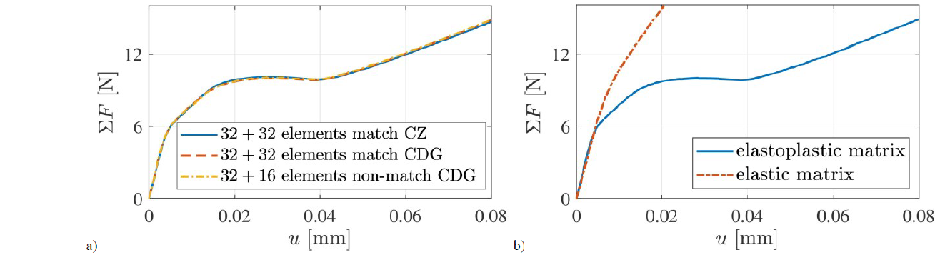
Fig. 7. Fiber composite structure. Reaction-force displacement for (a) matching vs non-matching meshes using intrinsic CZ and extrinsic CDG (b) different material responses in the presence and absence of plasticity for the mesh refinement level of 32+32 elements.
1.4 Conclusion
A recently developed novel extrinsic cohesive discontinuous Galerkin method was extended to model the failure at the interface of ductile materials. To this end, a cohesive zone model was implemented into the incomplete interior penalty Galerkin method. The discretization of the structure enables both matching as well as nonmatching meshes. The material model is elastoplastic for small deformations. Isotropic hardening with linear and Voce type variants were applied to investigate two different examples. Using nonmatching meshes were advantageous in the discretization of a fiber composite structure. This led to a reduction of the computation costs. Furthermore, the method showed to be free of volumetric locking due to the reduced integration of the boundary terms in the DG method. To avoid shear locking in elastoplastic materials, a selective integration scheme on the discontinuities could be of significance. This is currently under investigation.
Acknowledgements
Financial support of this work, related to the subproject A6, “Multiscale modelling of the damage and fracture behavior in nanostructured laminates”, of the Transregional Collaborative Research Center SFB/TRR 87 “Pulsed high power plasmas for the synthesis of nanostructured functional layers” as well as the project “Hybrid discretizations in solid mechanics for non-linear and non-smooth problems” - Project-ID 255721882 - SPP 1748, both funded by the Deutsche Forschungsgemeinschaft (DFG, German Research Foundation) is gratefully acknowledged.
