1 Introduction
Tube hydroforming process can form tubular material into various components and is widely utilized in the automotive industry and civil engineering as it can reduce vehicles and structures weight and decrease production cost. An accurate characterization of tube constitutive parameters is an important basis for a successful hydroforming process design and finite element simulation and optimization[1].
Tube hydraulic bulge test is an advanced method to evaluate the tubular material properties under complex stress state, in which the collected experimental data like internal fluids pressure and bulge height is fitted to analytical models for this process and the constitutive parameters can be determined[2]. Woo et al. are[3] the pioneer who determine strain-stress characteristics for tubular materials using hydro bulge test firstly and find that an application of axial compressive force can increase bugle size and tube strain magnitude.
A big progress is made by Fuchizawa et al.[4] who assume the tube wall is formed under plane stress state and derive the stress formulas along circumferential and axial direction. To calculate strain components, the bulge profile at tube center is approximated as a circular arc which can be measured by three transducers on their designed hydro press. Since their research, the following researchers have always used their formulas to calculate stress components in the bulge tests, only changing the assumptions of the meridional profile shape for the sake of simplicity. The profile shape at tube deformation zone could be assumed as elliptical curve[5], parabolic function[6] and two circular arcs[7]. One drawback for these study is in the stress calculation where the force equilibrium equation along axial direction is used under the application of hypothesis that tubular specimens ends and locking systems are regarded as integrated one.
In order to eliminate the influence of unreasonable assumptions, plastic strain-stress relationship is introduced into the analytical models for hydro bulge process. Bortot et al.[8] calculate the stress component along longitudinal direction based on flow rule i.e. the strain is proportional to corresponding deviatoric stress and no assumption for the bulge geometry is made. Koc et al.[9] derive the strain component along circumferential and radial direction using Levy-Mises plastic equation. However, the derivation of force equilibrium for small element at bulge top along radial direction neglects tube wall thickness, which reduces the accuracy of analytical models.
In this paper, several tube hydraulic bulge tests for 5049 aluminium are carried out on a flexible hydro machine and bulge height and tube pole thickness are collected during experiments. An analytical model based on total strain theory is developed to determine materials parameters using experimental measures. It considers the change of tube wall in the force equilibrium equation and introduces the plastic flow rule, which can increase its prediction accuracy. The results obtained by total strain model are used to compare with that from a classical model proposed by Hwang et al.[5] and tension tests.
2 Theoretical analysis
2.1 Geometrical analysis
The profile shape on tube deformation zone is assumed to be an elliptical curve[10], geometrical parameters are shown in Figure 1. Based on the geometrical relationship, the curve radius along the axial direction can be written as:

Then, the circumferential radius at the tube pole is describe as below:

Where R0 is the initial tube outer radius, L0 is the length of tube deformation and ℎ is the bulge height at tube pole.

Fig. 1. The geometrical parameters on deformation zone.
2.2 Strain analysis
The strain at the tube pole along the radial and circumferential direction can be calculated according to the definition of true strain, whose formulas can be given as following:
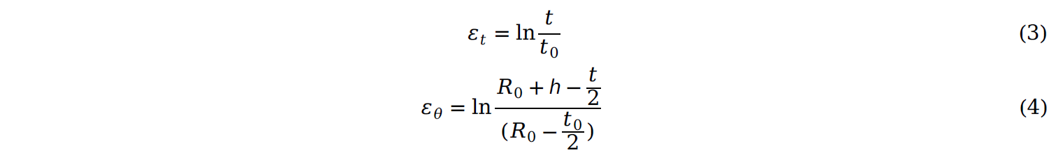
Where t0 is the initial tube wall thickness and t is the pole thickness after deformation. Based on the material incompressibility, the strain component along longitudinal direction can be derived as:

The tubular material behaviour is described by von Mises yield criterion and isotropic hardening model, so the effective strain can
be written as:

It can be seen from formulas above, the equivalent strain can be calculated when the initial tube diameter, wall thickness and bulge height are measured during experiments.
2.3 Stress analysis
The wall thickness of tubular specimen used in this research is very small compared with the tube diameter, so the tube deformation zone is assumed to be under plane stress state, which means the stress component along radial direction is zero. Figure 2 illustrates the stress state for a small element at tube bulge pole with distributed internal fluids pressure. The force equilibrium can be derived as[10]:

According to total strain theory [11], the difference in principal stress is proportional to that of principal strain, which can be expressed as:

Combining equation (7) and (8), the stress components along hoop and axial direction can be calculated as:
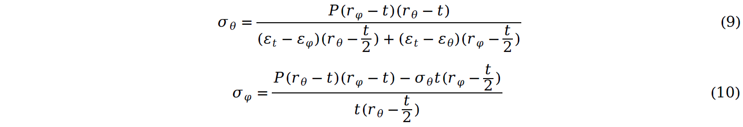
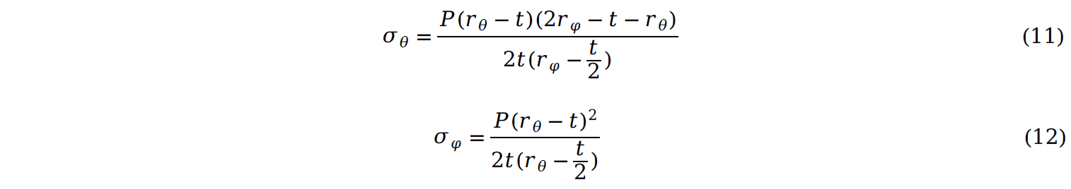
In Hwang’s research[5], a hypothesis discussed in the introduction is made and these two stress components can be expressed as following:
Therefore, stress components can be identified when the internal pressure and bulge height are recored in the tests. Based on von Mises yield criterion and isotropic hardening model, the effective stress can be given as:

The relationship between equivalent stress and strain is described by Hollomon power law:

where K is hardening strength and n is hardening exponent.
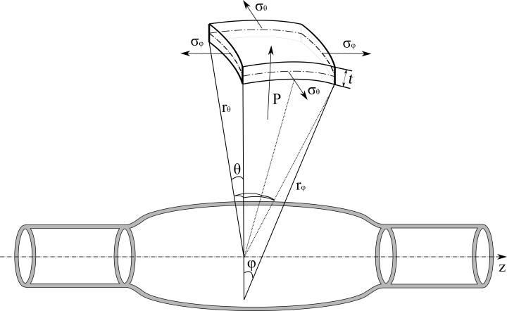
Figure 2. Stress analysis for a small element at bulged tubes
3 Results and discussion
In this research, 5049-0 aluminium alloy is tested, whose initial dimension with initial outer diameter 50.00 mm, thickness 1.08mm, and length 300.00mm. Hydraulic bulging tests for tubular specimen are performed under various pressure levels to determine the material constitutive parameters. Bulge diameter and pole thickness are measured by a micrometer when internal pressure reach the desired level, and these values are measured at different positions along circumferential direction to obtain a more accurate measure.
Figure 3(a) illustrates the profile shape for tubular specimens before and after deformation. It can be observed that tube ends are locked and the length for initial and deformed tube is equal by measurement, which means there is no axial displacement in tests and bulging mainly occurs in the middle of the tube. Figure 3(b) shows the recorded tube outer diameter and its corresponding fluids pressure. It can be seen that the bulge diameter is increased with higher internal pressure and its increase in high pressure zones is faster than that under lower pressure.
The collected experimental data is imported into formulas of total strain and Hwang model and several strain-stress points can be obtained. These resulting points are fitted to Hollomon hardening law using least square method and obtained flow stress curve can be given in Figure 4. A tensile specimen is cut from tubes along longitudinal direction and a universal tension test for it is performed on CMT electrical testing machine. To make a comparison, the effective strain-stress curve iobtained by this tensile test is also displayed in Figure 4. Corresponding materials parameters are summarized in Table 1.
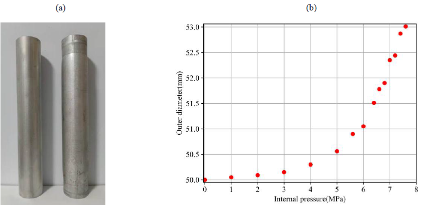
Figure 3. (a) Specimens before and after hydraulic bulging, (b) Relationship of internal pressure versus outer diameter
As it can be seen from the results, there are some differences for the curves and material parameters from the three methods and the strain-stress curve obtained by tension test appears to be higher than that based on total strain and Hwang model. The stress values from total strain model is higher than that obtained by Hwang model, especially at large deformation area. The tension test under uni-axial stress state overestimates the materials deformation limit under bi-axial tension stress state comparing with the bulge tests.
|
Hardening strength (MPa) |
Hardening exponent |
|
|
Tensile test |
396.75 |
0.297 |
|
Total strain model |
433.16 |
0.362 |
|
Hwang model |
418.08 |
0.366 |
Table 1. Material parameters from tube hydraulic test and tensile test
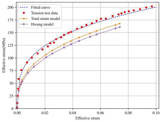
Figure 4. Comparison of flow stress curve determined by different models and tension test
In order to evaluate the performance of three methods, a FEM model for hydraulic bulge process is built using LS-DYNA program, as shown in Figure 5. In this model, solid element type is chosen and three elements are meshed through the wall thickness of tubes to produce an accurate response. Material behaviour is evaluated by von Mises yield criterion and isotropic power hardening law. Two tube ends are blocked to ensure there is no axial displacement. The obtained material parameters in Table 1 are imported into FEM models of tube bulging and the bulge height can be predicted. These results in the simulation are used for comparison with experimental data.
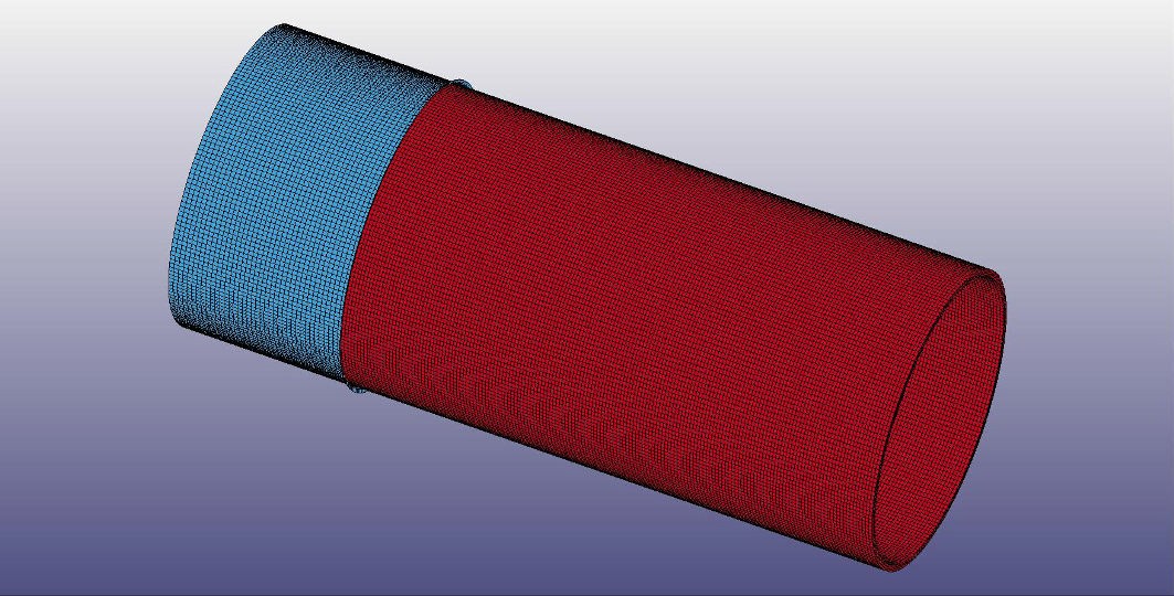
Figure 5. FEM model for hydro bulge process
Figure 6(a) illustrates the comparison of bulge height versus internal pressure curve predicted by FEM models input materials constitutive parameters given in Table 1. More detailed quantitative error evaluation for simulation responses to experimental data is plotted in Figure 6(b). As can be seen from these results, the predicted bulge height by tensile test has a smaller discrepancy to the experimental data than Hwang model at low internal pressure. However, the latter model leads to a better match to experimental data at high pressure range. The predicted bulge height by total strain model has a best agreement with experimental measures during the entire deformation process compared with the other two methods. This may be due to the introduction of total strain theory and the removal of a hypothesis for force equilibrium along longitudinal direction in Hwang model. It is possible to conclude that tube hydraulic bulge test is more suitable for characterization of tubular material than tensile test and total strain model is an accurate analytical model for hydro bulge process.

Figure 6. (a) Predicted bulge height versus internal pressure by FEM models, (b) Quantitative evaluation of simulation to experimental measures
4 Conclusion
Hydraulic bulge test for 5049-O aluminium alloy are performed to evaluate the flow stress curve of tubular material. An analytical model based on total strain theory is developed for post processing experimental data. To validate its performance, a classical theoretical model named Hwang model and universal tensile tests are used to identify material constitutive parameters for the same tube. FEM models for hydraulic bulge process using material properties from three different methods are built. The comparison shows that total strain model has a best agreement and the smallest deviation to experiment measures compared with the other two methods. It is concluded that the hydraulic bulge test is more suitable to characterize the tubular materials behaviour than tension test and total strain model perform better for post processing data from tube bulge tests.
