1 Introduction
The drilling process is widely used in the industry especially in the aeronautics and the aerospace industries. Its optimization is however complicated due to the difficult access to the cutting area and therefore to experimental data.
In various recent studies, the temperature during the drilling process is frequently evaluated by means of thermocouples inserted in the workpiece [1,2] or in the lubrification holes of the drill bits [3]. Infrared thermography is another used technique to evaluate the in-process temperature. For instance, researchers choose to use infrared pyrometry and a fiber optical like Sato et al who inserted the fiber optical in the lubrification holes in order to measure as close as possible to the cutting area [4]. Besides, the optical fiber can be inserted in the workpiece in the axis of the tool to evaluate the temperature below the cutting edge. In their work, Beno et al avoid damages by means of synchronized feed of the fiber and the tool [5]. Since these techniques only provide punctual or averaged information, other authors turned to the use of infrared camera to measure thermal fields during the drilling process [6,7]. In order to observe the thermal fields close to the walls of the hole, drilling tests are often carried out at the edge of the workpiece. Usually, inverse approaches are used to solve the thermal equations.
The aim of this work is to bring quantitative information about forces and energies (magnitude, distribution, origin) involved in the drilling process of Ti-6Al-4V titanium alloy. The first part of the adopted approach is to use experiments which enable to reveal such physical quantities at different scales. In this study, the limited access to the cutting area is overcome by the means i) of linear oblique cutting test at microscale (not presented in this present paper) and ii) tube drilling tests. Thermal fields are captured using an infrared camera while kinematic fields are captured by the mean of image correlation (DIC) using a high-speed camera. The experimental fields are then compared to the numerical results from two 3D FEM cutting model involving the same thermo-mechanical constitutive equations as presented in [8].
In this study, a 3D finite element model (FEM) of the drilling process is developed on ABAQUS/Explicit [9]. Machining processes are very regularly modeled by FEM, in particular the orthogonal cutting operation [8, 10, 11]. Girinon et al are also working on a 3D FEM model of the drilling process using a first model to obtain thermal loading and a second model to evaluate the residual stresses following the application of this loading [12]. In the present paper, only numerical and experimental results from the study of the thermal aspect of the drilling process will be presented.
2 Experimental Procedure

Fig. 1. Experimental set-up
Innovative millimetric drilling tests are carried out in dry conditions in a DMG DMU85eVo machining centre with a SECO coated twist drill with 11mm diameter. The pieces are speckled Ti-6Al-4V tubes in order to determine strain fields by DIC. The dimensions of these samples are presented in the Tab.1. Each test is realized with a spindle speed of 450 rev/min and a feed rate of 100 μm/rev. Visible images and thermal images are obtained using a fast camera (FASTCAM SA3) and an Infrared camera (FLIR SC7000), calibrated with a blackbody. These cameras enable the simultaneous measurements of kinematic fields (DIC) and temperature fields. The capture frequencies and integration time are set to 6000Hz – 1/6000μs and 600Hz – 100μs respectively. The spatial resolutions are 3.6917 μm/pixel and 47.9551 μm/pixel.
Table 1. Sample dimensions

The geometry of the tool cutting edge is complex and is composed of several sections with different cutting angles evolving along the edge. Studying the drilling process of tubes/pin of different diameters means looking at the cutting phenomena in different areas of the cutting edge (edge discretization approach – see zones 1, 2, 3 and 4 in Fig.1). The influence of the distance from the drilling axis on the cutting phenomena can then be evaluated or even quantified.
3 Numerical Modelling
3.1 Behavior and damage laws
The constitutive equation (1) and the damage model (2) implemented in the FE model are the ones used in the work of Harzallah et al [8]. The stress 𝜎 (1) depends on coefficients A, B and n which correspond respectively to the yield strength, the strain-hardening modulus and the strain-hardening exponent. The damage limit ε̄̄f (2) is obtained from an adaptation of the Mohr-Coulomb criterion with the proposed flow law (1). It depends on the same coefficients and also on the normalized Lode angle θ̄ and the maximum shear stress τf.

The values of these coefficients have been experimentally identified by Harzallah et al [8] for ranges of strain rate ε̇f and temperature T encountered in machining. This formulation enables an explicit coupling of the thermomechanical behavior and is not based on the addition of multiplicative terms [13]. Therefore, it can describe the behavior of the material without a priori assumption on the model of the evolution of strain hardening or damage according to the temperature T and the strain rate ε̇f.
3.2 Finite Element Model (FEM)
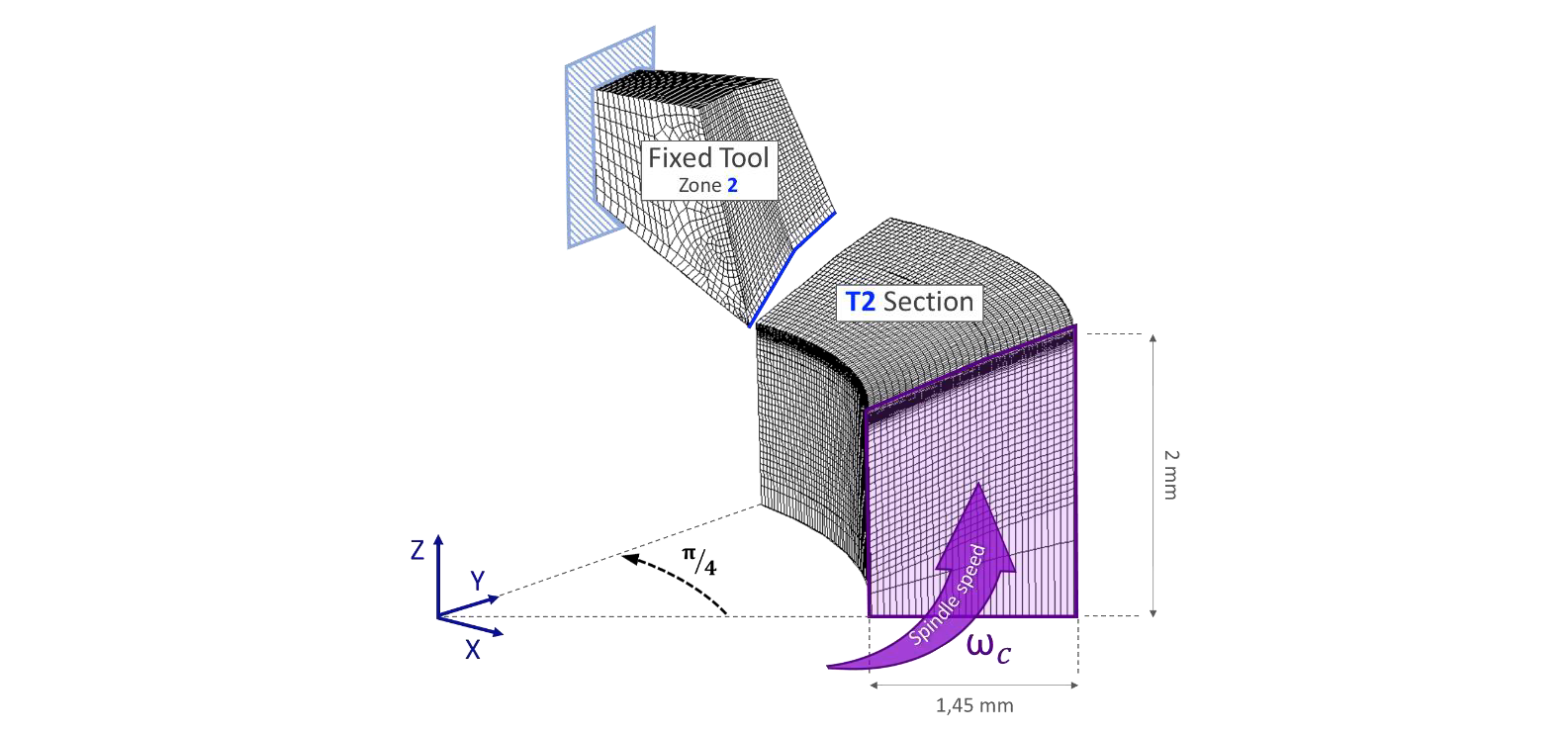
Fig. 2. 3D Thermomechanical Finite Element Model – Tube T2
For each sample, a numerical 3D FE model is implemented on ABAQUS/CAE software [9] with refined meshing in the cutting zone (about 500μm to 4.5μm) in order to simulate the drilling process with the matching experimental cutting conditions. The numerical parameters used in these models are presented in the Tab.2. For numerical stability sake, only one-eighth of a revolution is computed. Fig.2 shows the FE model developed to simulate the cutting phenomena during the drilling process for one of the samples (tube T2). To simplify the modeling, the tool geometry used in the model is an approximated geometry of the Zone 2 of the drill (see Fig.1 and Fig.2). In other words, the tool is reduced to the portion of the drill in contact with the tube T2 during the drilling process. The numerical models developed to simulate the cutting of other samples are implemented in a similar way. Unlike 2D numerical modelling in the literature, these models are 3D models which enable to avoid the use of a sacrificial zone (since the same constitutive, damage and friction laws are applied to the entire workpiece).

3.3 Finite Difference Model (FDM)
Table 2. Numerical Parameters (FEM)
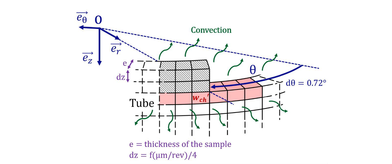
Fig. 3. 2D Thermal Finite Difference Model
To avoid FEM coupled resolution over a huge cutting distance, results of the model are extended over several turns by means of purely thermal 2D analytical model implemented on Matlab [14]. This thermal model resolves the heat equation (3) with finite differences method (FDM) and is able to manage element deletion (thus to evacuate heat through the chip).
Convecto-radiative boundary conditions are applied on every free surface (ℎ=50𝑊.𝑚−2.𝐾−1 and ε=0.9). Since the model is 2D-axisymetric, there is only one element according to e⃗r with a thickness of 𝑒. The surface temperature is approximated to the average temperature in the thickness which enables to estimate the term in 𝜕2/𝜕𝑟2 in the heat equation by a leakage term [15]. The heat equation obtained with this hypothesis is illustrated by (3).

Where 𝜌 is the density, C𝑝 the specific heat, 𝜆 the thermal conductivity, ℎ the coefficient of forced convection with air and 𝑟𝜖 the radiation leaks calculated using Stefan Boltzmann’s law. Lastly, T̃=T-T0 where T0=Tamb is the initial temperature assumed to be the same as the ambient temperature.
Finally, volume heat source 𝑤𝑐ℎ′ is applied on the first layer of elements under the tool (see Fig.3) and is directly evaluated from the FEM model under the same experimental conditions (cutting angle, cutting speed, feed rate, …).
4 Results and Discussion
This section presents numerical and experimental results especially from thermal study of the drilling process for two samples. Concerning the mechanical aspect, Fig.4a shows a visible image of the external surface of the speckled tube T2. Experimental equivalent plastic strains are calculated by digital correlation. The mean intensity gradients of speckles equal 14.0 for the tube T2 and 14.8 for the pin P. The subset size is 16x16 pixels in both cases. Equivalent plastic strains measured on a vertical line under the tool of the tube T2 and the pin P after a first pass of a tooth are presented in Fig.4b. These results highlight that the maximum strain values are higher for the pin P than for the tube T2. As the feed rate are the same for both tests, this difference could be explained by the different local cutting angle and cutting speed. Besides, it is relevant to notice that the depth affected by plasticity is around 100μm. However, the infrared camera resolution is 47.9551 μm/pixel so the heat flux assessment is possible in this area which corresponds to two superimposed IR pixel.

Fig. 4. Visible image and Experimental (DIC) strain results.
(a) Visible image of the speckled tube T2 (b) Equivalent plastic strain (DIC) on a vertical line under the tool after a first pass of a tooth - Tube T2 & Pin P
Fig.5a and Fig.5b present respectively numerical (FEM) and experimental (IR) thermal fields obtained in this study for the tube T2 and the pin P at the beginning of the drilling process. With regards to these results, it should be noted that the repeated passages of chip across the optical path and the camera compromise the visibility close to the cutting zone. Moreover, infrared images are motion-blurred near the cutting area and in the chip. Since the emissivity of the chip is very difficult to evaluate, the results in the chip correspond to those obtained with the same emissivity as for the speckled tubes, i.e. 0.9. Hence, the results obtained for the chip are highly faulted and will not be considered in the present work. Only the thermal aspects within the tube (where the IR measurement can be considered as valid) are discussed in the following.
At first glance, the figures Fig.5a and Fig.5b show that heat is mainly produced in the primary shear band and consequently drains off with the chip. However, these figures also reveal that heat that diffuses downward, within the tube/pin is far from negligible.
Besides, both numerical and experimental results (see Fig.5a-b) show a higher temperature in the chip for P than for T2. Such observation leads to assume that the amount of heat being evacuation in the chip is more important in the case of the pin P than in the case of the tube T2. In addition, the numerical heat flow diffusing within the workpiece (see Fig.5c-d) seems to be higher in the case of the tube T2 but this statement is hardly verified from raw experimental temperature images (see Fig.5b). Indeed, the temperature strongly depends on various parameters (geometry, boundary conditions, ...) and achieving a relevant confrontation in temperature between tests and calculations is very complex. In particular the estimation of the peak temperature is highly challenging due to the limited spatial resolution of the experimental means. For these two reasons, a power approach, less sensitive to such parameters, is preferred for the study on first revolutions of the drill.
The heat diffusing in the workpiece appears clearly in Fig.5c where the vertical heat flow is presented in the numerical case (FEM) and it is significant (between 6.106 and 107𝑊.𝑚−2 just under the tool for the samples T2 and P, see Fig.5d). Experimental and numerical heat flow are calculated using Fourier’s law deriving respectively experimental and numerical temperature results. Thus, heat flow values obtained just under the tool (area of 50μ𝑚 x 50μ𝑚) are presented in Fig.5d. There is a good fit between the heat flow calculated from infrared images and the one obtained by the FE model (differences between 6 and 12% with experiments, see Fig.5d).

Fig. 5. Experimental (IR) and Numerical (FEM) thermal results – Tube T2 (left), Pin P (right).
(a) Numerical thermal fields (b) Experimental thermal fields (c) Numerical vertical heat flow (d) Heat flow under the tool.

Fig. 6. 2D FDM Model – Temperature profile over 1 revolution (top) and 5 revolutions (bottom) – Tube T2 (left), Pin P (right)
As the drill progresses, it is possible to predict that the temperature in the direct surroundings of the cutting zone will increase progressively. That is why, in order to evaluate actual temperature of the cutting material at any moment of the drilling process, a 2D thermal macroscopic FD model is implemented (see Section 3.3). The volume heat source used to define the first passage of drill is obtained from the thermomechanical FE model. Indeed, this volume heat source is calculated from the numerical heat source whose relevance has been verified by experiment (see Fig.5d). This FD model enables to determine vertical temperature profiles in the depth of the external surface of the samples after several revolutions (see Fig.6). The peak temperature is overestimated numerically (see Fig.6) because of an excessive averaging of the localize temperature peak: the element size for the FD model is 25μmx25μm and the pixel size in infrared images is 48μmx48μm. Once again, temperature strongly relies on the geometry and the boundary conditions and therefore, reasoning with temperatures shows a substantial limit because generalizing is very complicated (as opposed to a power approach).
It appears that the numerical amount of dissipated energy in the workpiece (proportional to the areas under the curves in Fig.6) matches with the real heat energy inputted and transferred within the workpiece under such experimental conditions. Thus, the results presented in Fig.6 enable to validate the use of the heat source wch′ assessed from the FEM model. In addition, the temperature of the tube T2 and the pin P increase as the drill cut the material (see top and bottom images in Fig.6). It confirms that notwithstanding the heat evacuation through the chip, each drill revolution brings heat within the workpiece which ultimately sum up to a significant rise in the actual temperature of the cut material.
The FD thermal model enables to estimate the temperature evolution (see Fig.7) for an area of 50μmx50μm (equivalent to one IR pixel and two superimposed FDM elements) for point atop the generated surface, (thus at 500μm depth when drilling starts). The evolutions of the numerical and experimental temperatures have a similar behavior over time for the tube T2 and the pin P. Both show that the temperature increment between two consecutive passages of a tooth decreases, nonetheless, it drives to a significant and continuous increase of the temperature in the direct surroundings beneath the tool. In other words, this figure highlights the fast increase of the temperature of the cut material and confirms the previous statement. This heat storage can therefore increase the temperature of the tool, damage it, and disrupt the cutting mechanism. Besides, it appears that the heat storage is different for the tube T2 and the pin P: the amount of heat stored in the sample is more important for the pin P even though the heat input is lower (see Fig 4d). Indeed, an elevation of 150°C of the top surface is observed for the pin P compared to 100°C for the tube T2 after 5 revolutions i.e 500 μm drilled (see Fig.7). It is observed that even if the Pin P cannot dissipate power through a boundary condition at its center (conversely to Tube T2), it is only a marginal explanation of this phenomenon. Indeed, the circumferential conduction of heat is higher for tube T2 and lead to spread the higher heat input over a wider surface of material and thus decrease the temperature of the top surface. It is also worth noticing that in the case of real drilling conditions, the heat storage may be more important. Indeed, the cutting zone would be confined (heat dissipation would be difficult) and the drill would be fully engaged in the workpiece.
Finally, the temperature build-up within the workpiece does not stabilize over time and lead to slowly modify the mechanical properties as the cut progresses. This highlights the highly transient nature of the process and the complexity that results from its modeling.

Fig. 7. 2D FDM Model – Temperature over several turns
(a) Tube T2 (b) Pin P
5 Conclusion and Perspectives
The present work has enabled to obtain experimental data from an area that is reputedly difficult to access by means of original drilling tests. It has also highlighted the contribution of local coupled field measurements in the validation of a complex numerical model.
In addition, the developed 3D FE model has been validated by experiments on the one hand by means of comparison in power at the beginning of the drilling. On the other hand, the FE model has been validated after several revolutions using a purely 2D thermal model (whose the heat source is obtained locally from the FE model).
It has be shown that the in-process thermal loadings applied to the workpiece varies significantly along the cutting edge and that the relation between the power generated by the cutting phenomenon and the resulting increase of temperature of the material is far from obvious and deserve a greater attention from the community.
Finally, such extend thermal modelling has proven its ability to quantify the thermal energy dissipated within the workpiece, thus opening the door to the evaluation of surface degradation of the generated hole.
Acknowledgements
The authors thank the Region Occitanie for its financial support.
