1 Introduction
Titanium and titanium alloys have been utilized for high specific strength parts and members in airplanes [1] and for biocompatible tools in biomedical applications [2]. In their metal forming and forging, severe adhesion of work fragments and debris particles onto the dies induced their high friction and severe wear [3] and suppressed their workability. Since heat is generated at the contact interface between die and work materials, this galling behavior is enhanced when the interface temperature exceeds the critical temperature [4]. Hence, the reduction in thickness in its forming and forging must be lowered as much as possible to be free from galling, when using the tool steel dies or WC (Co) tools [5]. New die material selection with anti-galling capacity must be selected to be free from adhesion of fresh titanium surfaces and deposition of TiO2 debris particles onto the die surface. Thick SiC (Silicon Carbide) coating was proposed as a die material for upsetting the pure titanium wires [6-7]. No galling was detected on the SiC coating punch and die surfaces after continuous upsetting in fifteen shots. In addition, a titanium wire was successfully upset in cold and dry till the reduction of thickness reached to 35 % [8-9]. The microstructure analysis on the contact interface [10-11] taught that the galling-free forging process was sustained by the in situ solid lubrication on the contact interface.
In the present paper, these β-SiC-coated SiC punch and core-die are prepared for dry cold and warm forging of pure titanium and β-phase titanium alloy wires, up to a reduction in diameter by 70%. This high reduction forging becomes an essential step to shape the titanium and titanium alloy blank plates from their raw wires and bars in a single shot for fabrication of glass flames and biomedical tools. In the forging experiments, the CNC (computer numerical control) stamping system is employed to upset the titanium and titanium alloy wires by controlling the applied stroke in each reduction. The power-to-stroke relationship is in situ monitored to describe their upsetting processes. The surface area extension rate monotonously increases by the flattening of a circular wire to a thin plate without significant bulging deformation. The applied power also increases monotonically with the work hardening of titanium. SEM (Scanning Electron Microscopy), EDX (Electron Dispersive X-ray spectroscopy) and Raman spectroscopy were utilized to describe the contact interface condition between SiC coating and titanium work. After continuously forging in cold and dry conditions up to a 70% in reduction, a tribofilm is in situ formed radially from the center line of this contact interface. The carbon agglomerates isolated from β-SiC coating distribute in dots only at the center of contact interface. Intermediate titanium oxide thin films are formed in this tribofilm together with TiO2 debris. The warm forging of pure titanium wires is also employed to investigate the effect of process temperature on the forging behavior.
2 Experimental Procedure
2.1 Preparation of β-SiC coated SiC dies
Thick β-SiC coating with the thickness of 4 mm was deposited onto the sintered SiC substrate by thermal CVD (chemical vapor deposition) process at 1500 K. Both the punch head and core die were polished and cleansed by the ultrasonic cleaner. This SiC-coated SiC substrate was directly utilized as a punch, as shown in Fig. 1a. The diamond sawing was used to cut the rectangular groove as a cavity of core-die, as depicted in Fig. 1b. In the following experiment, the pure titanium and β-phase titanium alloy wires are forged into this cavity with the depth of 0.15 mm and the width of 10.0 mm. A half circular groove with the diameter of 0.3 mm was also cut into the bottom of groove to fix the circular titanium wire work. No cracks or defects were present in this SiC-coated SiC dies, even after thermal transients in CVD and mechanical finishing.
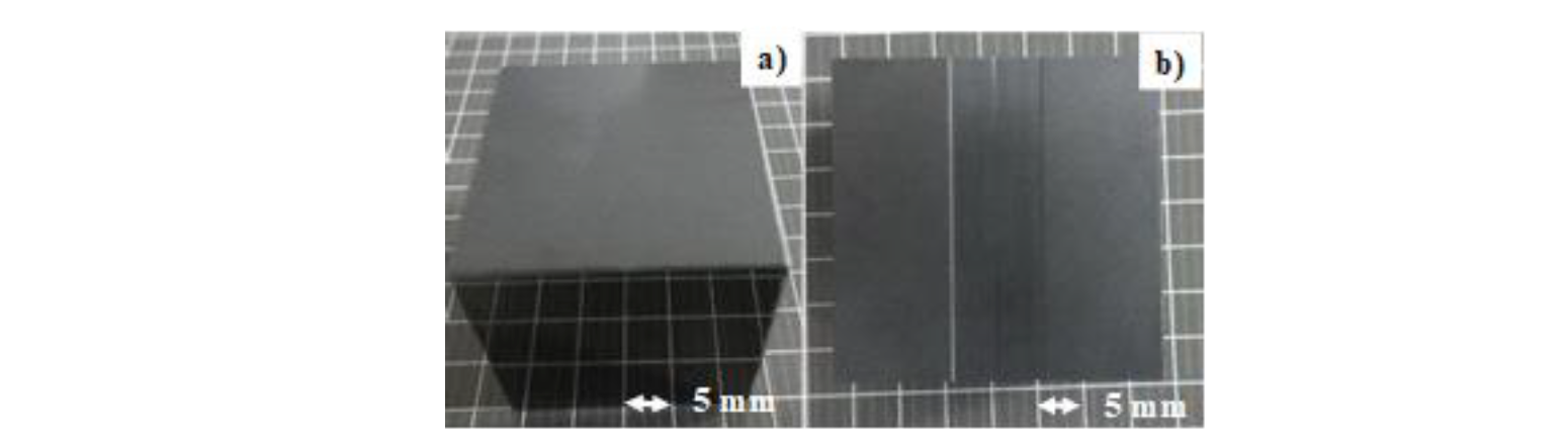
Fig. 1. SiC coated SiC punch and core-die for cold and warm forging experiments. a) SiC-coated SiC punch, and b) SiC-coated SiC core-die with a rectangular groove
2.2 Cold and warm forging system
These SiC-coated SiC punch and core die were fixed into the upper and lower die sets, respectively, as shown in Fig. 2. This die set was cemented to upper and lower bolsters of a CNC stamping system. Four motor-driving units worked independently from each other to adjust the eccentricity in loading. The stroke was lowered in a constant velocity of 0.1 mm/s down to the specified minimum stroke (δm), held for 1 s and then moved up to the original position by the same velocity. This δm was varied for each reduction in wire diameter. No interface delamination occurred before or after cold forging.

Fig. 2. Upper and lower cassette die system. (a) Upper die set with SiC-coated SiC punch, and (b) lower die set with SiC-coated SiC die
3 Results and Discussion
Cold and warm forging experiments in dry are performed to investigate the material flow during loading. The power–stroke relationship is in situ monitored to describe the flattening process from a circular wire to a thin plate. The reduction of thickness is varied up to 70% to describe the friction on the contact interface and to analyze the formation of the fresh surface in this flattening behavior. Precise analyses on the microstructure of contact interface is made to describe the titanium oxide debris film formation on the contact interface and to investigate the role of free carbon agglomerates from the SiC coating on the solid lubrication under dry cold and warm forging processes with a high reduction of thickness.
3.1 Cold forging of pure titanium wires
Pure titanium wires with the diameter (D) of 1.0 mm and the length of 10 mm were prepared for cold dry forging with the use of SiC-coated SiC punch and die. The reduction of thickness (r) was employed as a parameter to describe the forging behavior. Fig. 3 depicts the variation of forged wire to a flat plate with increasing r.
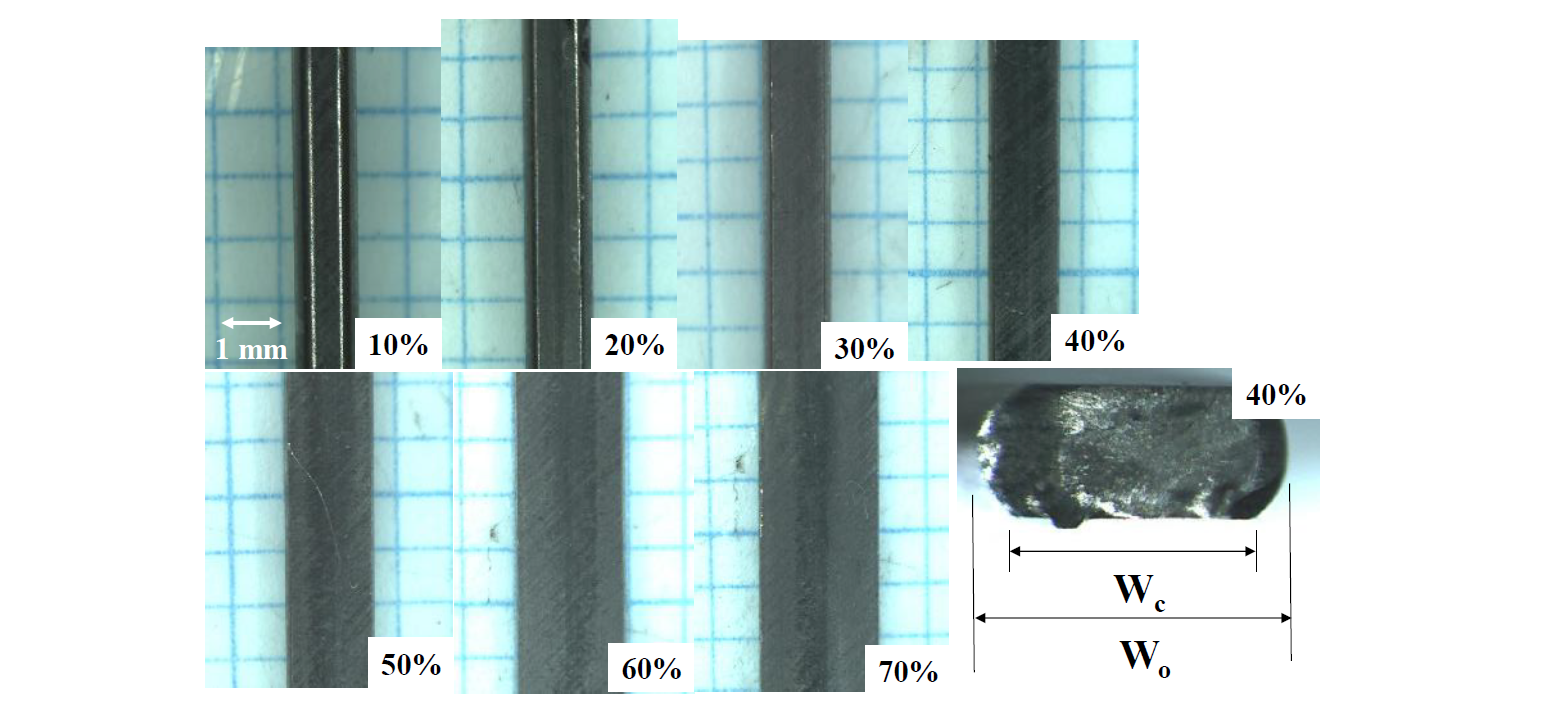
Fig. 3. Variation of the forged wires to the flat plates with increasing r. Original wire was forged to a flat plate with the thickness of 0.3 mm at r = 70%
When r < 20%, the wire was axially compressed; the width (Wc) of contact interface between the SiC-punch and titanium work is smaller than the width (Wo) of forged wire. With increasing r, Wc gradually approaches to Wo, and, Wc ~ Wo for r > 60%. After [12], the non-dimensional bulging deformation (Bg = (Wo –Wc)/2D) for the initial diameter of wire is used as a parameter to estimate the friction coefficient (µ) on the contact interface during forging. If µ ~ 0 on the contact interface, Bg could become nearly zero and the work would laterally deform in the uniform plastic flow velocity in forging. If µ >> 1, the bulging deformation could dominate the whole forging behavior even with increasing r. As depicted Fig. 3, Bg ~ 0 and titanium work deforms to a flat plate. The monotonic decrease of Bg with aid of the prediction model in [12], implies that the friction coefficient monotonously lowers with r and approaches to 0.05 to 0.1 for r > 50%. This homogeneous plastic flow of titanium wire in the lateral direction must be sustained by the lubrication mechanism on the contact interface of SiC coating to the work.
3.2 Analysis on the contact interface of SiC coating punch to forged titanium wires.
A SiC-coated SiC punch was utilized for continuously cold dry forging the titanium wires in 10 shots with r = 70% to form the steady-state contact interface. SEM–EDX (JOEL, Tokyo, Japan) and a three-dimensional profilometer were utilized to analyze the contact interface condition between the SiC coating and the titanium work. Raman spectroscopy (Nihon-Kogaku, Co., Ltd., Tokyo, Japan) was also used to analyze the binding state of silicon, carbon, titanium and oxygen on the contact interface. Fig. 4 shows the optical and SEM images on the contact interface on the β-SiC coated SiC punch.
As had been reported in [10,11], this contact interface consists of two regions in Fig. 4a; e.g., a black zone or the region-A at the center of the contact interface and white the zones or the region-B, sand-witching this black zone. Fig. 4b shows the low resolution SEM image on this contact interface. These two zones are formed in the radial direction from the center line of the initial contact interface between the titanium wire and SiC coating. The black zone consists of black and dark gray layers growing in the radial direction. This black zone width is equivalent to the fresh surface width in Fig. 3; the formation of this black zone has close relation to the flattening process in the cold dry forging. In addition, pure titanium work flow in Fig. 3 with less bulging behavior implies that this black zone could be a tribo-film to suppress the adhesion of fresh surface and to lower the friction coefficient against the flattening plastic flow.
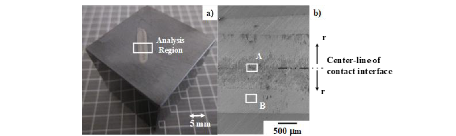
Fig. 4. Optical microscopy and SEM analyses on the contact interface conditions of SiC-coated SiC punch after dry cold forging up to r = 70% for 10 shots. (a) Optical microscopy image on the SiC coating after cold forging test, and (b) SEM images on the black and white zones
Higher resolution SEM and EDX analysis were made on this region-A in Fig. 4b. Fig. 5a depicts the SEM image on the centerline of contact interface between the β-SiC coating and the forged titanium work. Element mapping of oxygen carbon, silicon and titanium is compared in Fig. 5b. This thin film with the thickness less than 1 µm consists of two zones on the β-SiC coating; e.g., the a-zones are carbon agglomerates and the b-zones are titanium oxides. Since no carbon dots are detected in trace level before forging, these carbon dots are formed by isolation of free carbon solutes from the carbon supersaturated β-SiC matrix.

Fig. 5. High resolution SEM image and element mapping on the region-A in Fig. 4b. a) SEM image on the region-A, and b) element mapping of oxygen, carbon, silicon and titanium on the region-A
Raman spectroscopy was utilized to demonstrate that this tribofilm consists of the free carbon isolated from β-SiC coating as well as the titanium oxides on the contact interface. Fig. 6 shows the Raman spectra measured by wide scanning at the region-A on the contact interface. Three positions {A1, A2, and A3} were selected in this region-A for Raman-spectroscopic analysis. A1 was located in the b-zone in Fig. 5a, A2 is in the a-zone and A3 is near the b-zone. The distance among A1–A2 and A2–A3 was constant by 5 µm. As stated in the literature [13], two broad D and G-peaks are detected at the Raman shift of Λ = 1300 cm−1 and 1600 cm−1, respectively. This proves that a-zones detected in Fig. 5b are not titanium or silicon carbides but they are free or unbound carbon agglomerates. That is, a free carbon is present at the center of the contact interface in correspondence to high carbon agglomerates in Fig. 5b. This free carbon isolation from carbon supersaturated β-SiC coating at the center of contact interface, reveals that high stress transient in upsetting of titanium wires by SiC punch and die induces the diffusion of supersaturated carbon solutes from β-SiC matrix to its punch surface. These precipitated free carbon dots work as a solid lubricant to reduce the friction on the interface and to drive the uniform plastic flow in the lateral direction along the contact interface as seen in Fig. 3.
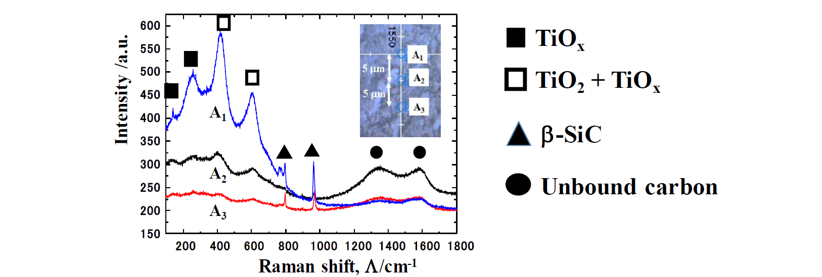
Fig. 6. Raman spectra measured at three positions in the region-A, {A2, A2 and A3} in Fig. 4b
Two narrow peaks at Λ = 800 cm−1 and 950 cm−1, respectively, with weak intensities reveal that β-SiC punch surface coexists with a tribofilm. Compared to high intensity peaks at β = 800 cm−1 and 950 cm−1 just outside of the contact interface, their peak intensities are much smaller. This implies that the contact interface on the SiC coating punch is mainly covered by the tribofilm as well as the carbon dots. Other peaks than these two include a broad peak detected around Λ = 200 ~ 600 cm−1. If TiO2 were present as a titanium oxide in the interface, the narrow peaks could be detected at Λ = 400 cm−1 and 600 cm−2, respectively. No detection of those narrow peaks implies that titanium oxide film consists of various binding states in the titanium - oxygen system from TiO to TiOx through the intermediate Magneli phase oxides. In particular, other broad peaks at Λ = 150 and 250 cm−1 suggest that the intermediate titanium oxides or TiOx are formed together with TiO2 debris particles in the tribofilm.
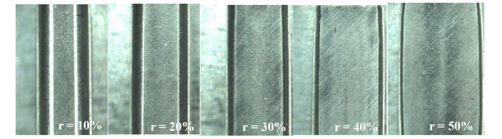
Fig. 7. Variation of the forged β-phase titanium wire width with the initial diameter of 3.0 mm with increasing r
3.3 Cold forging of β-phase titanium alloy wires
The β-phase titanium wires with the diameter of 3 mm have been utilized as a raw material to make near-net shaping into glass frames and biomedical tools in multi-step forging and annealing processes [14]. These β-phase titanium alloy wires were employed as a work material in the forging experiment to demonstrate that β-SiC coating punch and die are also free from the galling to β-phase titanium. In the similar manner to dry cold forging of the pure titanium wire with the diameter of 1.0 mm, β-phase titanium with the diameter of 3.0 mm and the length of 10 mm was upset to each reduction of thickness. Fig. 7 describes the variation of its forged β-phase titanium wire width with increasing the reduction of thickness, r. The original wire was uniformly upset to a rectangular plate at r = 50%. The contact interface width (Wc) approaches to the total width (Wo) of upset wires for r > 40%; at r = 50%, Wc ~ Wo and Bg ~ 0. This monotonous reduction of bulging deformation down to be nearly zero with r implies that in situ solid lubrication works to reduce the friction coefficient without galling in this cold forging of β-phase titanium wires.
3.4 Warm forging of pure titanium wires
The galling behavior is enhanced at the contact interface between the coated dies and the metal works during the warm and hot metal forming at the elevated holding temperature (TH) [15]. This is because the interface temperature easily exceeds over the critical temperature (> TH, or ~ TH) by the working heat generation. The holding temperature was incrementally varied from 373 K to 673 K by 100 K to investigate the effect of holding temperature to warm forging behavior of pure titanium wires with the use of β-SiC coated SiC punch and die.
The loading velocity was also 0.1 mm/s. Fig. 8 compares the plain views of four forged titanium wire up to r = 65% at these holding temperatures. The width of contact interface (Wc) was the same among these forged wires and Wc ~ Wo at r = 65% irrespective of the holding temperature. This reveals that this warm forging process takes place with lower friction and without galling on the contact interface in the similar manner to the cold forging processes in Figs. 3-6. In order to demonstrate this insensitivity of forging behavior to the holding temperature, the measured power to stroke relationships at each holding temperature are compared to that in the cold dry forging. No difference among the measured power to stroke relationships at each r, proves that the in situ solid lubrication works to drive the warm forging with high reduction of thickness, irrespective of the holding temperature. This warm forging behavior suggests that high reduction upsetting from a wire to a flat plate is performed even at RT due to the in situ solid lubrication. No additional heating and thermal annealing as well as no multi-step forging are necessary by using this β-SiC coated SiC dies.
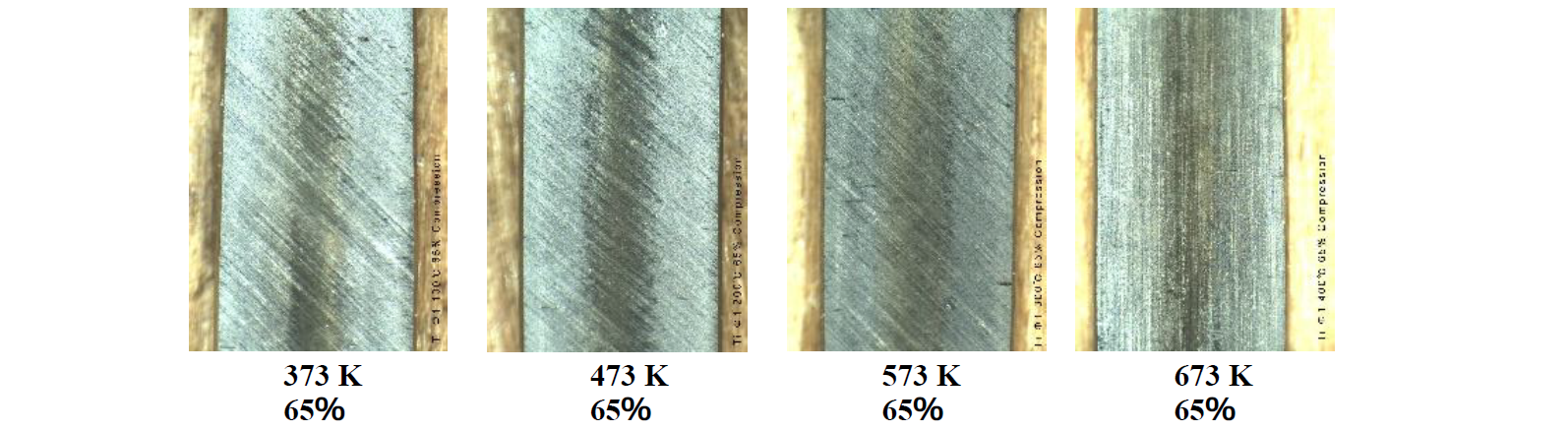
Fig. 7. Variation of the warm forged pure titanium wire width when the initial diameter of 1.0 mm in increasing r

Fig. 8 Power to stroke relationships at each holding temperature of 373 K (100 ℃), 473 K (200 ℃), 573 K (300 ℃) and 673 K (400 ℃), respectively
To be noticed in Fig. 7, The interface of forged wire at 673 K only has no scratching traces by transcribing the ground head surface of β-SiC coating in different from other cold- and warm forged titanium wires. This might be because of the thicker tribofilm formed on the contact interface when TH > 673 K.
4 Conclusion
The β-SiC-coated SiC die system was proposed to make cold and warm forging of titanium and titanium alloys. A cylindrical pure titanium wire with the initial diameter of 1.0 mm is uniformly upset to a flat plate with the thickness of 0.3 mm within a single shot not only in cold but also in warm conditions. The additional heating and thermal annealing as well as multi-step forging processes were necessary in the normal industrial production lines but are never needed under the solid lubrication by in situ formation of a tribofilm on the contact interface between β-SiC coated SiC punch and titanium work. In particular, the unbound carbon films isolated from the carbon supersaturated β-SiC coating matrix, play a role to reduce the friction at the initial contact condition with high stress transients and to drive the flattening process with uniform plastic flow velocity. The β-phase titanium alloy wires are also forged in cold and dry with low friction and without galling to β-SiC coating die surfaces. The forged wire surface is composed of the fresh titanium and titanium alloy surfaces from wire matrix; this metallic-shining surface is attractive to the near-net shaping process as the secondary step to fabricate the titanium and titanium alloy parts and tools.
Acknowledgements
The authors would like to express their gratitude to Mr. S. Kurozumi (Nano-Coat Film, llc.) for his help in experiments. This experiment was financially supported in part by METI-program on the supporting industries at 2020.
