1 Introduction
The cross-section of bonded filaments constituting 3D printed parts by fused material deposition may be considered as a representative element for the description of their porous mesostructure [1, 2]. There is currently a lack of equations representing such geometry. Lemniscates as plane algebraic “8” shape curves may be efficient in this purpose. Indeed, they have been successfully used for the modeling of ceramic sintering kinetics in the case of cylindrical filaments [3]. Then, we propose using the hot melt sintering of thermoplastic filaments based on a 3D printable biopolymer as a model-case. We will demonstrate the ability of the lemniscates of Booth to fit the contour of their cross-section. The characterization and modelling of the viscous sintering kinetics of filaments, or powders, used in additive manufacturing are of renewed interest. Various image acquisition systems are described in literature, to follow the coalescence of such divided solid materials. Ad-hoc instrumented ovens, or thermo-microscopy devices are used [4-6]. The subsequent image analysis generally consists in evaluating the length of the bonding neck, x [m], between the two coalescing objects : cylindrical filaments or spherical geometries of diameter d [m] are generally assumed (as observed from a side view in the case of filaments). The bonding angle θ [rad] is thus given by equation (1). In the case of cylinders, a Lemniscate model was proposed and solved numerically by Hopper [3, 7]. This model allows the estimation of the characteristic time for viscous sintering tvs [s], from θ experimental values:

tvs is linked to the material’s thermo-rheological properties, with Ri the initial thermoplastic part radius [m], μ, the viscosity of the molten material [Pa.s] and Γ, its surface tension [N.m-1]. Determining tvs makes it possible to define the processing window of a thermoplastic material, as applied to the deposition of a biopolymer : zein, a storage protein extracted from corn, plasticized by 20w% glycerol. Indeed, its characteristic viscous sintering time was found below 100s at temperature above 120°C, similar to values of amorphous polymer, ABS, classically used in additive manufacturing at its printing temperature [7]. In the present work, we intend to use the lemniscates of Booth and, contrary to Hopper’s pioneering approach, a new equation allows relating directly the sintering kinetic parameters to the contour of the cross-section of the coalescing filaments, without the previous estimation of the bonding neck, x. The entire geometry of the system, i.e., the complete contour profile of two coalescing filaments, is now taken into account. This novel approach is not limited to the initial phase of sintering and allows taking into consideration swelling and/or 3D edge effect phenomena that are known to occur [8]. Therefore, a theoretical lemniscate of Booth can be adjusted to the closest of the edge of the filaments’ contour during their hot melt sintering. It is expressed in Cartesian coordinates according to Hopper’s approach [3] and can be also described in a polar coordinate system [9]:

with α ∈ [0; 2.π[; R0, the final radius of the inverted ellipse (R0= √2.Ri); parameter m ∈ [0; 1[, in Cartesian coordinates (Eq. 3), and parameters a (i.e., the size coefficient), as well as B, the shape parameter [-] in polar coordinate system (Eq. 4); 𝜑 [rad], defined as α-π/2 from Hopper’s work, to match in polar coordinate system.
The objective of the present study was to set up and implement this novel method of image analysis. It enhances the characterization of viscous sintering properties of thermoplastic materials and provides constitutive parametric equations of the successive inverse ellipses that match their evolving geometry.
2 Material and methods
2.1 Biopolymer-based extruded filaments and isothermal sintering
Zein powder is mixed with 20w% glycerol, used as plasticizer, in a household kneader. Then, the resulting powder blend is extruded through a cylindrical die with a twin-screw micro-compounder (Haake Minilab ; Thermo Scientific GmbH ; Karlsruhe, Germany), as previously described [7] (Øfilament ≈ 2 mm, Lfilament = 5 mm). An instrumented oven, with a transparent glass-made front and equipped with three LEDs for the backlighting, is used to follow up the sintering at Tset = 120 °C of two adjacent extruded filaments, thanks to a CMOS camera. Such device allows the images acquisition of the juxtaposed filaments cross-section (1 frame.s-1 ; 8 bits coding), with an average resolution about 200 pixel.mm-1. The temperature of the filaments, Tfilament [°C], is measured with a thin thermocouple (type K, Øthermocouple ≈ 0.4 mm) placed inside one of them, previously drilled to its half-length. A second thermocouple was located in the medium part of the oven to measure the environmental temperature (Toven, [°C]).
2.2 Morphological image analysis
From 8-bit coded images acquired during sintering, the analysis is performed after cropping to focus on the two filaments (Fig. 1-a). A segmentation step is carried out, by image thresholding. Then, binary images are obtained with one white object (i.e., pixels = 1) on a black background corresponding to the backlighting (i.e., pixels = 0).
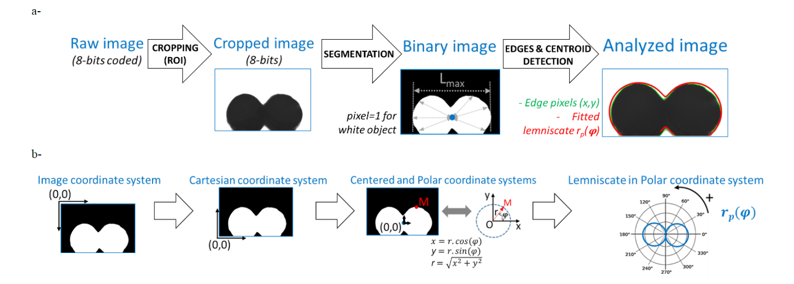
Fig. 1. Image morphological analysis to obtain the filaments edge pixels during their sintering (-) and the fitted lemniscate (-), based on each raw acquired image (a-). Coordinate system changes, from a standard image coordinate system to a polar one, and schematic representation of a lemniscate of Booth (b-)
Gray level threshold is determined visually using ImageJ free software (National Institutes of Health, USA) and applied subsequently to each image of the whole sintering sequence. The successive steps, (i) cropping, (ii) segmentation and (iii) Morphological Image Analysis (namely “MIA”, based on edges detection and determining objects centroid), are carried out starting from raw acquired images. Each point of the filaments contour is thus determined in (x, y) coordinates. The fitting of the corresponding lemniscates of Booth was done with Matlab® software (The Math Works Inc., Natick, MA, USA) (Fig. 1-b) and the morphological image analysis is applied first on each binary image to identify the contour pixels by an erosion step on the digital mask corresponding to the filaments shape (with a 3*3 pixels2 structuring element). Then, the determination of the centroid point of the white object (filaments) of the binary image is carried out. This allows the computation of the maximum horizontal length of this object, Lmax [pxl]. Finally, the fitting of a lemniscate of Booth corresponding to the contour of the filaments is performed in a polar coordinate system from the model of Sowinski and Jasion, 2019 [9] (Eq. 4).
For the last step of the MIA, a conversion from the raw image coordinate system to a polar one is first required. Then, images are vertically centered on the ordinate at which the horizontal length of the white object is maximum (i.e., where Lmax is determined) and, horizontally, at the abscissa of the centroid, which is equivalent to a central point for the filaments (Fig. 1). Using the least square method of Matlab® Solver makes it possible to optimize the value of the shape parameter B of the polar equation rp(𝜑) of the fitted lemniscate of Booth. Changes of the size of the two sintered filaments correspond to the size coefficient determined by image analysis, a = Lmax/2 [pxl].
3 Results and discussion
3.1 Sintering sequence and parameters of the successive fitted lemniscates of Booth
The least square method allows optimizing the equation of the lemniscates of Booth in polar coordinate system. It is thus possible to identify the shape parameter, B, of the equation rp(𝜑) from the work of Sowinski and Jasion (Eq. 4). Such polar curves match the contour of the filaments during sintering, even if changes modify their shape. First, an initial pure viscous sintering, up to 1 minute at 120°C, and then viscoelastic swelling combined with hot melt spreading (Fig. 2). Superimposed to the raw images acquired with the instrumented oven in their associated coordinate system, the successive lemniscates of Booth fit the edge pixels of the thermoplastic filaments during their whole sintering sequence.
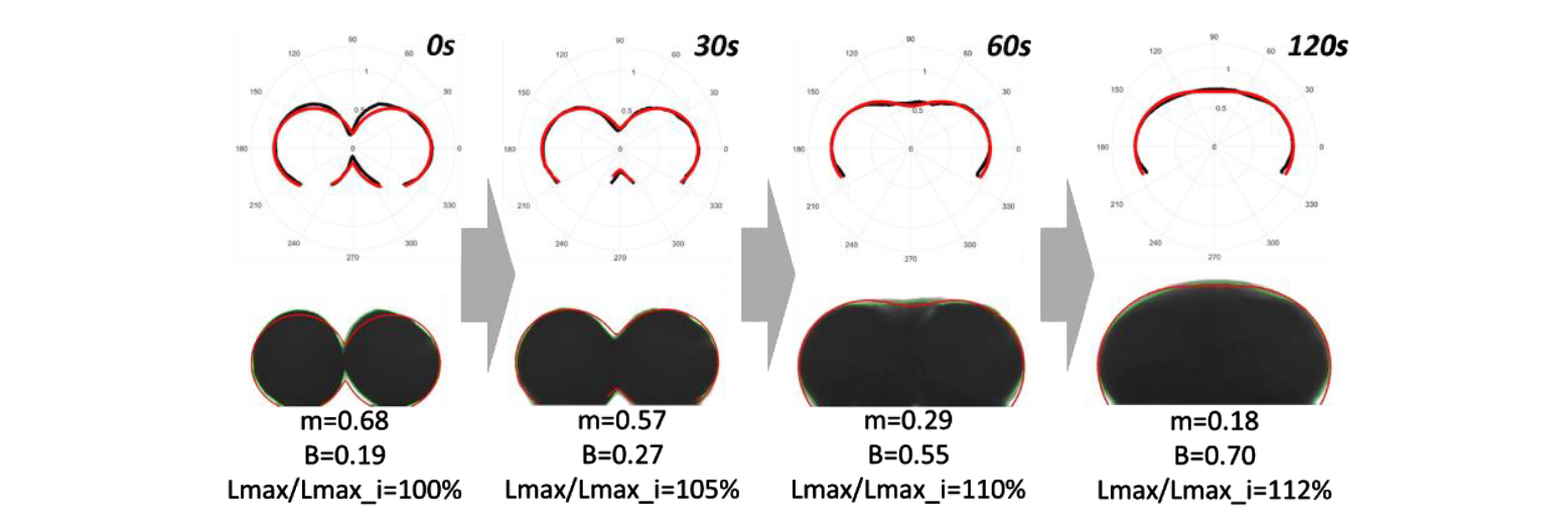
Fig. 2. Plot of the successive lemniscates of Booth (-) fitted to filaments contour (-) in a polar coordinate system during the sintering sequence carried out at T = 120°C (as presented on the top line of the figure, at t = 0s, 30s, 60s and 120s). Superimposition of the lemniscates of Booth (-) on the raw acquired images (8-bits coding), with filaments edge pixels (-) and with the successive values of parameter m from Hopper’s work (1984) [3], as well as parameters B and Lmax/Lmax_initial from Sowinski and Jasion (2019) [9] (as presented on the bottom line of the figure, at t = 0s, 30s, 60s and 120s)
The parameter m, issued from the equation of Hopper’s work (Eq. 3), can be assessed from the shape parameter B of the Sowinski and Jasion’s approach (B increasing from 0.19 to 0.7 during 2 minutes of the sintering trial at 120°C; Fig. 2), with :

Values of the parameter m decrease from 0.68 to 0.57 (30 s), 0.29 (1 min) and 0.18 (2 min). Finally, the increase of the size coefficient is 112% as computed from Lmax_initial determined on the first image, because of sintering followed by swelling and melts spreading (Fig. 3). It is stable after 2 minutes, as well as the shape parameter, while disappearing the concavity between the two initial juxtaposed thermoplastic filaments. It is noticeable that the oven is regulated at Tset = 120°C and it was measured to take about 20 s for the environmental temperature, Toven, to return to Tset, once the sintering sequence begins after closing glass window.
Obviously, it takes more time for the filaments core to reach the surrounding temperature in the oven. However, as sintering takes place at the filament outline, it is assumed that the material reaches a steady state after 20 s. This corresponds to the starting point of the increase of the parameter B from Sowinski and Jasion’s work (2019) [9] and the opposite evolution, as a progressive decrease, of the parameter m from Hopper’s approach (1984) [3] (Fig. 3).
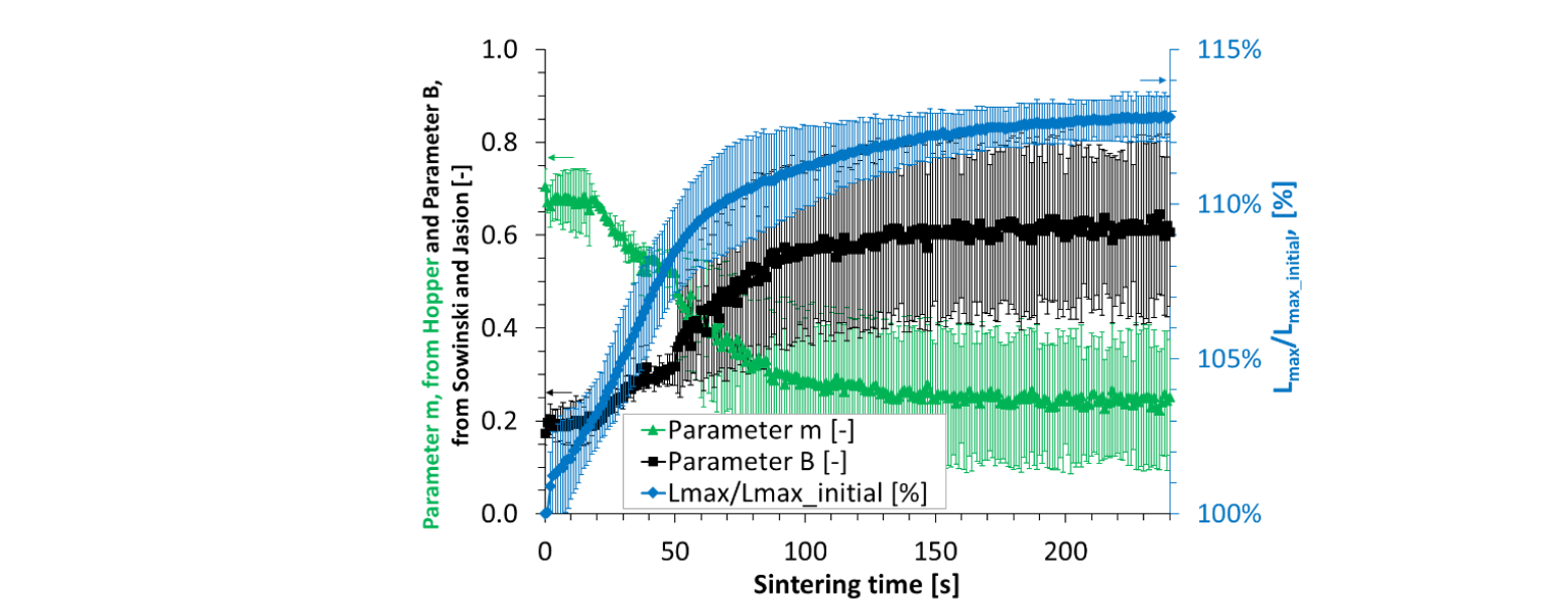
Fig. 3. Evolution of the parameters of the successive lemniscates of Booth fitted to the thermoplastic filaments contour during their sintering at T = 120°C : m, from the Hopper’s work (1984) [3], as well as B and Lmax/Lmax_initial, from the Sowinski and Jasion’s approach (2019) [9]
3.2 Characteristic viscous sintering time
The characteristic viscous sintering time, tvs, is derived from the evolution of m2 presented in the Hopper’s work (issued from the values of the parameter m in Eq. 3) [3]. It decreases during sintering trials, from about 20 s to about 1 min at 120°C (Fig. 4) and allows the determination of the slope in the initial sintering step, dm2/dt, found about -6.0.10-3 ± 2.4.10-3 [s-1]. Then, the use of Hopper's chart makes it possible to obtain a theoretical master curve (Fig. 4, as inserted at the right top of the chart) and its polynomial fitting.
For values of m2 decreasing from 0.4 to 0.2, in the range from 20 to 60 s at 120°C, the theoretical coefficient

is assessed at -0.473, based on the extrapolation at the average value selected at m2 = 0.3. This is linked to the experimental slope by the characteristic viscous sintering time, tvs :

The determination of the characteristic sintering time is then possible, here found at tvs = -0.473/-0.006 = 78.8 ± 31.8 [s]. This value is similar to the one evaluated by the measurement of the bonding neck length alone and its evolution during sintering trials, as presented in a previous work [7]. This result confirms the processing window defined for the plasticized zein in AM-ME, by comparison to the values of tvs obtained for standard thermoplastic polymers processed by 3D printing in the molten state.
In the present case, it is assessed from the initial sintering step of the full images sequence, now being entirely followed-up by such an enhanced image analysis method, allowing also the characterization of the swelling and the final melt-spreading step of the acquired images sequence.
The successive lemniscates of Booth’s parameters evolve in a similar way as the one found in previous work, with the possible use of the Hopper’s chart characterizing the whole envelope shape factor of two theoretical sintered round parts (parameter m2). Contrarily to classical approaches based on the measurement of the neck length, it corresponds in the present work to the exact monitoring of the coalescing filaments contour and its modeling, from 2 tangent divided solids (i.e., the two juxtaposed cylinders placed in the oven initially) to a sole round melt at the end of the complete sequence.
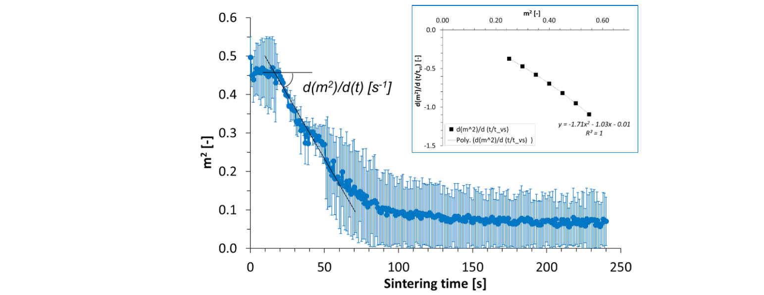
Fig. 4. Evolution of m2 during filaments sintering at 120°C and theoretical evolution of the decrease rate of m2 in relation to the characteristic viscous sintering time, tvs, plotted vs. m2 during a theoretical sintering (master curve from Hopper, 1984 [3] ; as an insert at the right top of the figure)
4 Conclusion
Lemniscates of Booth equations can be used to model the evolving contour of two coalescing thermoplastic filaments. Numerical fitting of such equations during their viscous sintering is an efficient method for the characterization of the characteristic viscous sintering time. An advanced image analysis method is proposed allowing the monitoring of the filaments cross-section in the case of pure viscous sintering occurring during initial coalescence, as well as in the case of eventual viscoelastic swelling and/or melt spreading, that occur for longer times for the material studied here. Such results open perspectives of using lemniscates of Booth to model the local geometry of 3D printed parts and to predict their porous structure.
Acknowledgements
The authors would like to thank D. Lourdin, G. Della Valle, K. Cochet, P. Papineau (INRAE, Nantes) and Y. Madec (Univ. Nantes) for helpful discussions and experimental support.
