1 Introduction
Forming processes in general and cold extrusion in particular offer ideal conditions for the efficient production of high performance metal components in the automotive industry due to the uninterrupted fibre flow in the pressed part, strain hardening, a high surface quality and short cycle times. Basically, cold forging enables the near-net-shape or net-shape production of functional components, such as gears, drive shafts, screws, etc., in highly economical processes [1, 2, 3]. Due to the constantly increasing requirements in the automotive industry, more precise as well as time and material efficient cold forging processes are necessary, which may only be achieved by innovative tool concepts. Especially in the cold extrusion of metallic components, reduced reject quantities, a higher shape and dimensional accuracy as well as an increased surface quality are required. Due to the extreme tool loads during cold extrusion, fulfilling these requirements is considered a complex problem which requires an intelligent process data monitoring and control system. For this purpose, both sensors and actuators have to be integrated into cold extrusion tools in a contour-close and structurally optimized design. The manufacture of such tools by conventional production methods is usually associated with time and cost-intensive processes and usually leads to suboptimal results, for which reason additive manufacturing technology can provide a suitable solution.
The additive manufacturing technology offers a variety of advantages, including a high freedom of design, the possibility of integrating functional elements such as sensors and cooling channels, and a high availability. These advantages have already been demonstrated in industrial fields such as machining technology [4], plastics technology [5], hot forging [4, 5] and sheet metal forming [6] in order to produce tools with increased performance. The increased performance of tools in industrial production can lead to both ecological and economic improvements and even to technological limits being exceeded. However, additive manufacturing has so far not been applied in the field of cold forging, due to low manufacturing accuracy of additive manufacturing processes, low surface quality of the additive manufactured components, insufficient hardness values of previously available powder materials and a lack of innovative tool concepts. In the meantime, high-strength and high-hardness powder materials are available for additive manufacturing processes. In addition, the manufacturing accuracy and surface quality of metallic components that can be achieved with additive manufacturing processes are being progressively increased. Current additive manufacturing processes can ensure sufficient component quality, enabling the production of cold extrusion tools after machining or spark erosion. By integrating functions such as temperature regulation systems, temperature and strain sensors as well as actuators for mechanical expansion compensation into cold extrusion tools, a technological leap can be achieved, which allows a wider range of metallic components to be produced by extrusion. In metal forming technology, this may be achieved by integrating functions in cold extrusion tools obtaining a process digitisation by means of new adaptive control concepts. As a result, an expansion of the feasible component spectrum in cold forging with simultaneous enhancement of press part quality could be realized. In the framework of a study at the Institute for Metal Forming Technology (IFU) of the University of Stuttgart, a cold extrusion die for full forward impact extrusion was developed according to the design possibilities of additive manufacturing technology. Accordingly, functional cavities and hollow spaces were introduced into the cold extrusion die in order to enable the integration of sensory and actuator functional elements. The aim of this study was the elaboration of a process data acquisition system and a process control system for cold extrusion by applying additive manufacturing potentials.
2 Tool design
The novel design of the cold extrusion die with cavities for integration of functional elements is shown in Figure 1 a). As a special feature the innovative cold extrusion die shows a vertical division, whereby the two halves are intended to be connected by fitting screws. Main dimensions of the cold extrusion die are Ø 52.1 mm x 60 mm, with the die cavity realizing a strain of φ=0.4. Several functional elements were integrated into this tool. A total of 24 lubricant nozzles with a diameter of 0.3 mm were arranged along the tool bore in order to enable the application of impact extrusion oils during the forming process and thus a selective manipulation of the tribological system. The lubricant nozzles are used for application of additional lubrication when loading a new billet. Therefore, the impact extrusion oil must be applied through the nozzles before the billet is placed into the die, in order to ensure that the outer surface of the billet gets completely covered with impact extrusion oil while the billet is inserted. The billet inserted in the die is deliberately positioned below the nozzle openings to avoid damaging of the nozzle opening during the extrusion process. In addition, the cold extrusion die was designed with a parallel, close-contour cooling channel system in order to enable targeted control of the die temperature in the process. Furthermore, two channels for the subsequent implementation of two Fibre Bragg Grating (FBG) sensors were added to the die. The cold extrusion die within the scope of the study was manufactured by the additive manufacturing Selective Laser Melting process by use of the sinter material 1.2709 and was heat treated afterwards. Subsequently to the additive manufacturing process, the two tool halves were post-processed by machining in order to achieve the required tool requirements. Figure 1 b) illustrates one half of the die after the machining process.
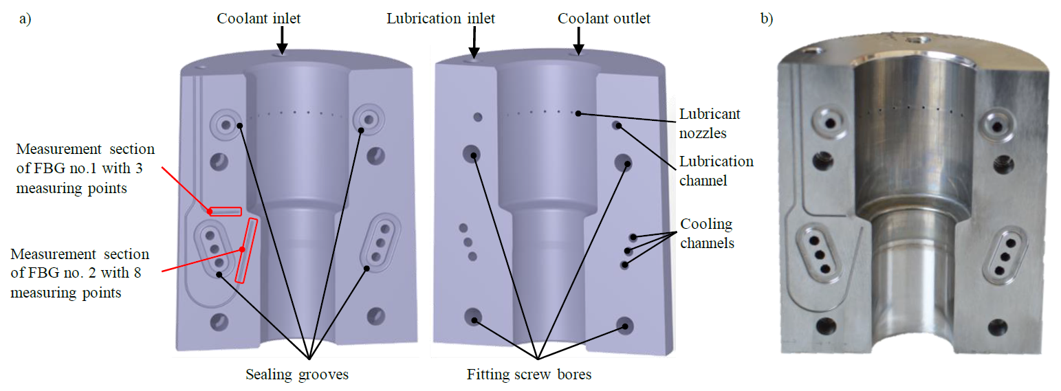
Figure 1: Design of the novel cold extrusion die with integrated functional cavities for additive manufacture, a) 3D-Modell, b) manufactured die after machining
Fibre Bragg grating sensors are fibre-optic sensors with a diameter of 125 μm, which enable the measurement of the process variables temperature, strain and pressure. The operating principle of FBG sensors is based on a periodic modulation of the refractive index along the fibre core which acts as a resonance structure. This structure is generated by a UV laser directed transversely onto the fibre, which creates an interference pattern in the core of the fibre with the aid of a phase mask [1, 2]. If light having a wide bandwidth penetrates the optical fibre and irradiates the FBG, only a small spectral width of the light, in the range of the so-called Bragg wavelength, is reflected. In the transmitted part of the light, this spectral component is missing, as shown in Figure 2. The basic operating principle of an FBG-based sensor system is based on the detection of the displacement of the Bragg wavelength, which correlates with a change in the measured variables (e.g. strain, temperature) [10]. In the case of strain measurement, a material locking of the fibre to the component material is required to transfer mechanical strain as well occurring in the component to the sensor [11]. In contrast, temperature measurement based on the thermal strain of the sensor explicitly requires a loose fit of the fibre in the component in order to prevent a possible transmission of mechanical strain to the sensor and the resulting distortion of the measurement results [12].
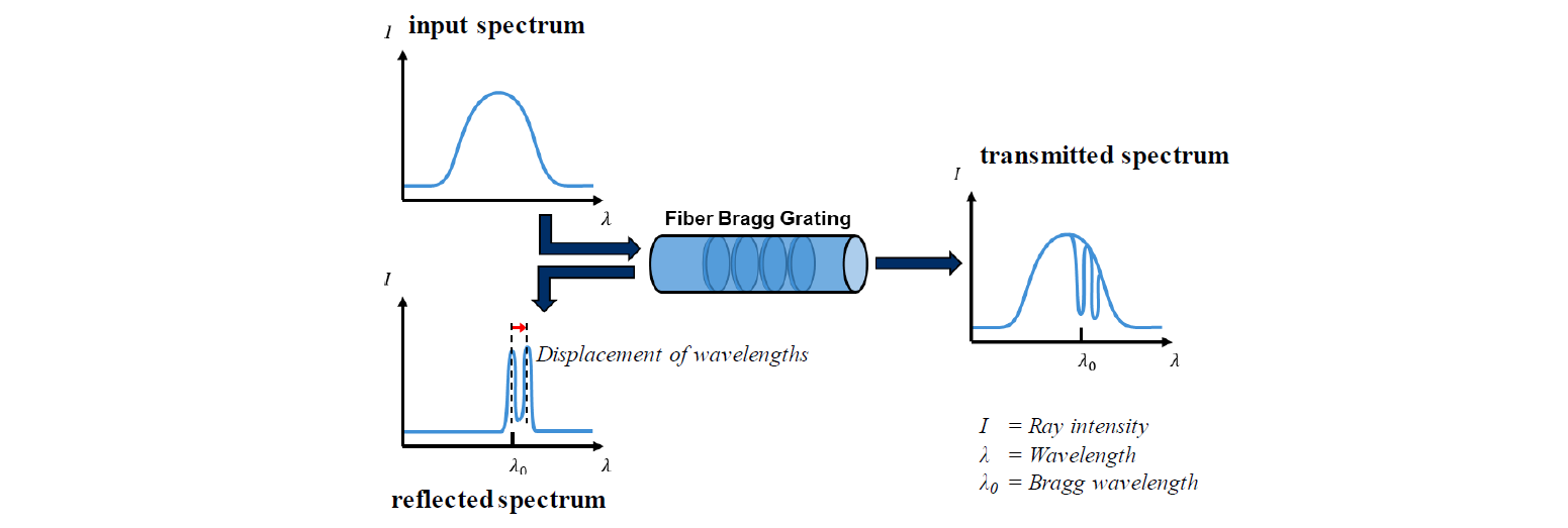
Figure 2: Operating principle of fibre optic sensors such as Fiber Bragg Grating sensors according to [3, 10]
In this study, the material-locking integration of one of the two FBG sensors to enable strain measurement was omitted initially. The basic feasibility of additively manufactured cold impact extrusion tools with structural weaknesses was to be demonstrated. In addition, the functional elements integrated into the cold extrusion die were to be validated in order to achieve a methodical elaboration of the aimed process digitisation. Therefore, the vertical division of the cold extrusion die was intended to enable a subsequent material-locking connection of FBG sensors for strain measurement by using adhesives. It is also possible to apply additional sensors such as strain gauges in the dividing plane of the die.
3 Numerical investigations
3.1 Simulation setup in DEFORM 3D™ for numerical investigation of the structural mechanical properties of printed die
A numerical investigation of the novel cold extrusion die was performed using the FE software DEFORM 3D™ in order to analyze the structural-mechanical properties of the die during the cold forging process. The simulation setup used for this purpose is shown in Figure 3 a). Due to the rotational symmetry of the cold extrusion die, the numerical model could be reduced to half of the entire extrusion tool in order to improve the computational performance. The structural-mechanical FE analysis of the cold extrusion die was performed in two steps. In the first step of the simulation, the reinforcement of the cold extrusion die was simulated by means of a shrink-fit operation. Subsequently, in the next numerical operation, the reinforced cold extrusion die was transferred to the actual cold forging process. As a result of this procedure, the structural-mechanical behavior of the cold extrusion die could be investigated numerically both after the reinforcement and during the cold extrusion process. In order to obtain a detailed knowledge into the stress state that occurs within the additively manufactured cold extrusion die during the cold extrusion process, a so-called "Die Stress Study" in DEFORM 3D™ was used for the second simulation step. In this "Die Stress Study", the cold forging process was first numerically modelled by means of a rigid and reinforced die in order to generate the resulting normal forces on the forming die cavity during the extrusion operation. Subsequently, these normal forces were applied to an elastic model of the cold extrusion die, which allowed a detailed numerical analysis of the elastic deformation as well as of the resulting stresses within the die. The simulation settings for this numerical investigation are shown in Figure 3 a). The data for the workpiece material of 16MnCr5 and the shrink ring material of 1.2714 were obtained from the database of the DEFORM 3D™ software. Data for the tool material of 1.2709 were generated by material characterization consisting of tensile, compression and notched bar impact tests using additive manufactured test specimens of 1.2709. All test specimens for the material characterization were manufactured using the additive manufacturing process of Selective Laser Melting.
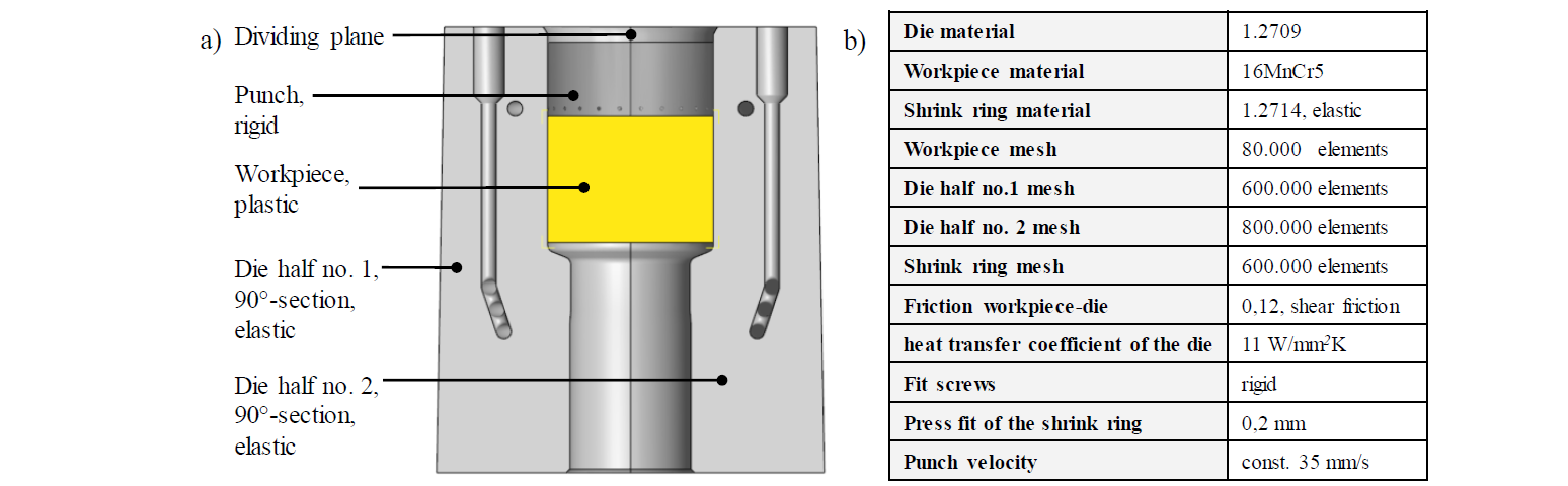
Figure 3: a) Simulation setup in DEFORM 3D™ for numerical investigation of the structural-mechanical die properties, b) Simulation parameters
3.2 Simulation setup in DEFORM 3D™ for numerical investigation of the tool temperature
For validation of the tool temperature occurring in the experiment, a numerical investigation of the experimental endurance test with the forming material 16MnCr5 was conducted. The simulation was performed with the FE software DEFORM 3D™, also using the simulation setup shown in Figure 3 a). All tool components were defined as rigid objects in order to maximise the computational performance. Furthermore, the shrink ring was excluded from modelling and the workpiece made of the material 16MnCr5 was defined as ideally plastic. The material data of 16MnCr5 were obtained from the database of the DEFORM 3D™ software. The simulation settings for the numerical modelling of the experimental endurance test were based on the experimental test procedure. Here an average stroke rate of 4 strokes/min at a ram speed of about 35 mm/s was reached. A total of 45 strokes were numerically mapped by using the “cycle” operation in the simulation software. The resulting die temperature was determined by means of point tracking (at the measuring points of the FBG sensor no.1).
3.3 Results of numerical investigation
The numerically calculated data of the "Die Stress Study" for the strain and stress distribution occurring in both halves of the extrusion die are presented in Figure 4. From Figure 4 a) it can be observed that the vertical division of the die causes an inhomogeneous radial expansion of the die along its circumference. However, this is a low inhomogeneity of only about 0.008 mm, which may reduce the accuracy of the pressed part marginally but does not prevent the feasibility of the process.
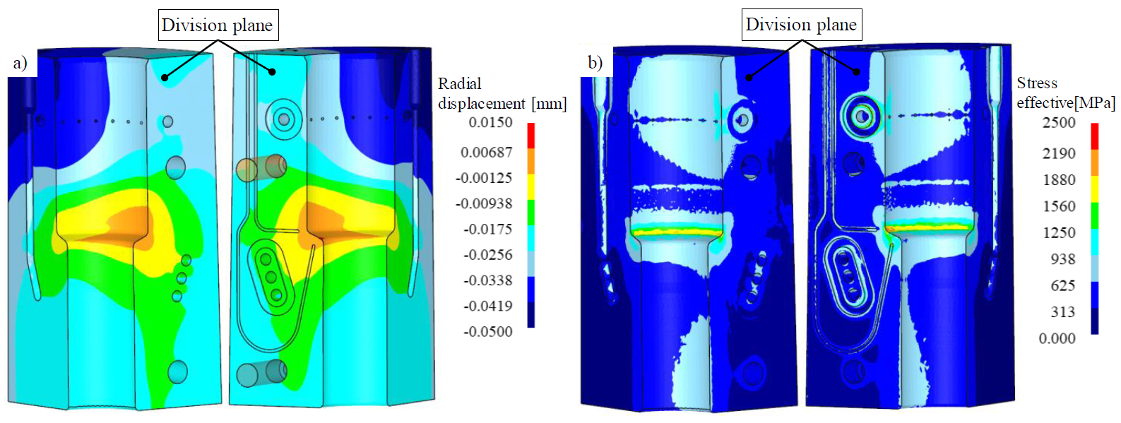
Figure 4: Numerical results of the “Die Stress Study” using DEFORM 3D™ software, a) numerically determined radial displacement of the extrusion die, b) numerically determined stress distribution within the extrusion die
In addition, Figure 4 b) indicates that no critical stress peaks occur in the area of the division plane of the die, as well as in the lubricant nozzles and the cooling channels. Thus the stress values in the die does not exceed the yield strength of the material 1.2709 of Re=2.050 MPa determined in the material characterization of additive test specimens. Both halves of the die and the shrink ring are therefore sufficiently dimensioned to withstand the stresses occurring during forming.
The numerically calculated die temperature is presented in chapter 4.2 (Figure 8) as comparison with the experimentally measured die temperature.
4 Experimental investigations
4.1 Experimental test setup
The experimental tool depicted in Figure 5 a) was installed in the mechanical press MAY MKN2-600/14 in the test field at the Institute for Metal Forming Technology ( University of Stuttgart in order to perform the experimental endurance tests. The test tool installed in the press was equipped with appropriate connections for using the cooling system and the lubrication system. Furthermore, the FBG sensor no.1 was inserted into the intended channel of the cold extrusion die. The experimental endurance test using the workpiece material 16MnCr5 was conducted by sequential manual loading of the billets into the test tool. All experimental test specifications are shown in Figure 5 b). Despite additional lubrication by means of the integrated lubricant nozzles, the billets were phosphated and preventively coated with molykote to prevent failure of the additive manufactured die during the experiment. The endurance tests are intended to demonstrate the feasibility of additive manufactured tools in cold forging. Furthermore, the functional elements integrated into the cold extrusion die were tested with regard to their operability and sensitivity to changes of process conditions.
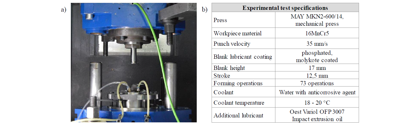
Figure 5: Experimental test setup, a) experimental tool, b) experimental test specifications
4.2 Experimental test results
Prior to the start of the experimental endurance tests, the lubricant channels integrated in the extrusion die and the associated lubricant entry into the die cavity were investigated. The functional testing was done without the insertion of a billet, allowing to observe the lubricant entry into the die cavity. The impact extrusion oil Oest Variol OFP 3007 used in the experimental endurance tests was injected into the lubricant system of the die. Figure 6 illustrates the results of these tests on the distribution of the impact extrusion oil in the die cavity. Thereby an even lubricant entry into the die cavity was achieved on the circumferential surface of the die cavity. This ensures an even lubricant layer thickness on the outer surface of the billet with impact extrusion oil when placing the billet into the die.

Figure 6: Experimental preliminary test for functional inspection of the lubricant application by means of lubricant nozzles
Subsequently, endurance tests were performed with 73 billets consisting of 16MnCr5 using the test tool illustrated in Fig. 5 a). During the performance test, the die temperature was measured by means of the FBG sensor no. 1 with three measuring points (shown in Figure 1 a)) inserted into the die. In addition, for each forming operation the punch force was measured by using the load cell in the upper tool frame. The measured test data were evaluated and are presented in Figure 7.
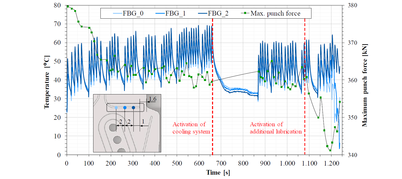
Figure 7: Results of the experimental endurance test performed using the material 16MnCr5 with measured temperature profiles at measuring points FBG 0-2 on the FBG sensor no. 1 and presentation of the maximum punch force during each forming operation
The curve of the maximum punch force as a function of the number of forming operations indicates an abrupt decrease of the maximum punch force within the first ten forming operations. It is assumed that the reason for the decrease in the maximum of the punch force is due to the reduction of the friction coefficient of molykote lubricant due to the increase in tool temperature [14]. In the further course of the experimental endurance test, the tool temperature increases steadily and reaches a maximum of almost 70 °C after the 45th forming operation. During the period between the tenth and the 45th forming operation, the measured maximum punch force decreased due to the constantly increasing tool temperature and the corresponding reduction of the friction coefficient. After the 45th stroke, the cooling system was activated and the die temperature was reduced from 70 °C to 31 °C within approx. 200 seconds. As a result of the reduced tool temperature an increase of the friction coefficient of molykote lubricant can be assumed, which resulted in an increased maximum punch force at the 46th stroke. Thus, a stabilisation of the maximum punch force between the 46th and 62nd forming operation was detected. It is assumed that the sensor was touched during the manual insertion of the billets, resulting in a fluctuation of the measuring signal.
The tool temperature measured during the experimental endurance tests was numerically calculated too by using the simulation software DEFORM 3D™ and the simulation set-up described in chapter 3.2. A comparison of the numerically and experimentally determined tool temperature is presented in Figure 8. The numerically determined die temperature was recorded by "point-tracking" at the same measuring points on the die during the experiment. Based on this comparison it can be observed that the numerically determined die temperature increases gradually especially at the start of the endurance run and is at the beginning of the process clearly lower than the experimentally measured die temperature. In the following course of the computational endurance test, the simulatively determined die temperature approaches the measured die temperature in the experiment. After approx. 600 seconds of the endurance test, the numerical as well as the experimentally determined die temperature have attained a similar temperature level. A major reason for the numerical deviation could be an imprecise implementation of the friction coefficient between workpiece and die. Furthermore, the heat conductivity value of the die material defined in the simulation may be a cause for a temperature deviation between experiment and simulation. Therefore, a validation of the simulation is required in the further progress of this study in order to adjust the numerical results to the experimental results.
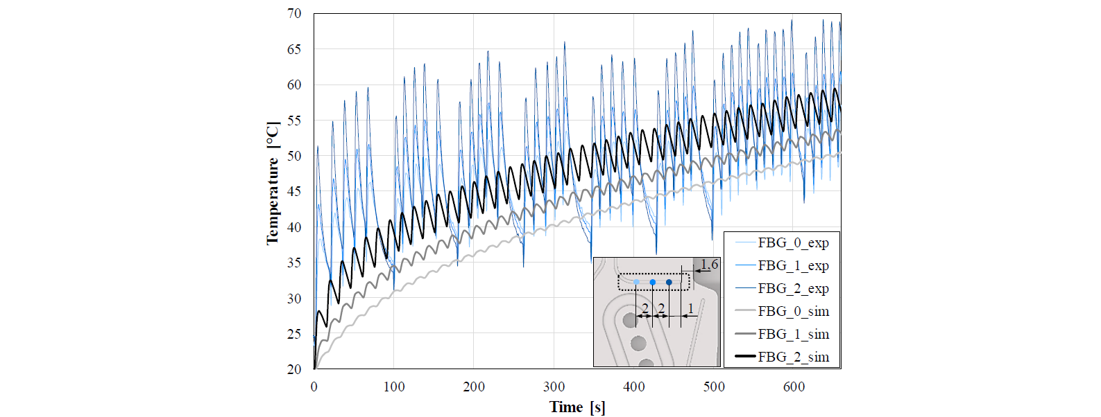
Figure 8: Comparison of numerically and experimentally determined die temperature
5 Summary and conclusion
In the context of this study a cold extrusion die with the design potentials of the additive manufacturing process Selective Laser Melting could be developed. For this purpose, near-contour cooling channels, a lubricant system for additional lubrication and two sensor channels for the subsequent application of glass fibre sensors (FBG sensors) were introduced into the die. The die was also designed with a vertical division in order to enable a subsequent material-locking connection of one of the two FBG sensors to enable strain measurement as well as the removal of broken FBG sensors out of the sensor channel. By means of numerical simulations using the DEFORM 3D™ software, the tool was analysed with regard to its structural-mechanical properties and optimised by corresponding iteration loops. After the design of the impact extrusion die the test tool was assembled. Experimental tests were performed to demonstrate the feasibility of an additive manufactured tool in cold forging and to evaluate the integrated functional elements. Therefore, an experimental endurance test with the forming material 16MnCr5 was conducted. In this experimental endurance test, the tool temperature was measured using a FBG sensor and the punch force using a load cell mounted in the upper tool frame. Especially the FBG sensor offers an outstanding potential for tool applications in cold forging, since several relevant process parameters (e.g. temperature, strain, pressure) can be measured. Due to the very small dimensions of the sensor multiple sensors can be integrated into one metal forming tool without any relevant negative impact on the structural mechanical properties of the tool. In addition, it was shown that the integrated cooling system and the integrated additional lubrication system in the die enabled a controlled manipulation of the cold forging process in terms of a tribological and thermal process modification.
Acknowledgements
The authors gratefully acknowledge the financial support by the “Arbeitskreis für Entwicklung und Erforschung des Kaltpressens”.
