1 Introduction
In recent years, the challenges in automotive production regarding sophisticated, brand-defining design specifications and as well as outer skin surface quality standards have increased rapidly [1]. While premium manufacturers have distinguished themselves in past decades by technological leadership, for example in terms of efficient engine design, improved driving safety and lightweight body design, today the technical aspects of vehicles are increasingly converging across brands and vehicle segments [2]. As a result, premium car manufacturers nowadays additionally stand out from their competitors due to their high-quality craftsmanship and the high surface quality of outer skin car body panels. An attractive design awakens the emotionality of a vehicle and is a key sales argument [3].
In order to ensure the quality of a vehicle body in terms of its appearance, the relevant quality characteristics of surface and shape (contour), flushness and gap dimensions of outer skin sheet metal parts must be considered thoroughly [4,5,6,7]. Therefore, analytical and numerical methods are used today to achieve a high surface quality of such dimensional characteristics of part during the very early product development process. Here, compensation strategies are developed in order to ensure specified gap dimensions or the flushness of component groups and avoid tolerance fluctuations occurring during the assembly of component groups [8,9]. Furthermore, the manufacturability as well as the appearance quality of folding loops can be predicted numerically/analytically, thus increasing the quality of vehicle bodies with regard to gap dimensions between outer skin parts [2]. Even irreversible shape deviations of the vehicle body that occur during paint drying processes can be numerically predicted and evaluated in order to develop suitable strategies to compensate these deviations [10].
According to [3], FEM simulation is also used to predict surface defects such as skid lines on unpainted car body components. Such skid lines are caused by an unbalanced draw-in of the part flange and thus by an undesired relative movement of the sheet metal material over structural edges or small radii in the center area of the punch surface. As a consequence, this leads to a linear plastic bending deformation, which is an offset of the sheet cross-section by a few micrometers and can be optically perceived as a line, depending on the angle of view [11,12,13]. When considering strain in the sheet metal, it can be noted that the greater the ratio between sheet thickness and tool radius, the greater the strain. By correlating this observation with the restraint force or stress, the so-called skid line limit diagram (SLLD) may be obtained (Fig. 1a)). It clearly shows that the skid line only occurs within a certain load range. The much larger area of the SLLD marks a kink [14]. Wanintradul et al. [14] therefore divide the resulting surface defects into two categories: kink and skid line. Thereby, the local curvature of both sides of the sheet appear equivalent in case of a kink, whereas skid lines do not show the same curvature on both sides (Fig. 1b) and c)). In contrast to a kink, however, skid line areas show a significant change in sheet thickness. Therefore, thinning is used for predicting skid lines in the FE simulation in [3].
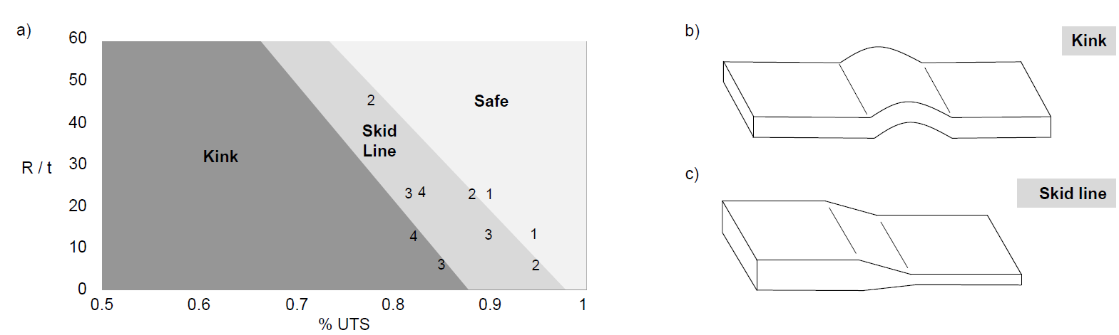
Fig. 1. Kink and skid line.
(a) Skid Line Limit Diagram (SLLD), (b) comparison of the kink and (c) the skid line [14]
Skid lines are often unavoidable for interior or structural components of vehicle bodies, but do not cause visible surface defects relevant to quality and therefore do not lead to scrap. However, if such surface defects arise on the outside of outer skin parts, in many cases this may lead to scrap. Thus, deep drawn parts showing skid lines in the central area in many cases will be rejected, since reworking them is too cost intensive. In general, skid lines can only be eliminated after occurrence by time-consuming and cost-intensive reworking of the respective tool [11].
Today, FEM simulations can only predict skid lines on unpainted body parts, although the final paintwork of parts usually leads to a significant increase in their visibility. Thus, no direct statement can be made about the quality relevance of a skid line of the painted part [3]. For this reason, this paper presents a new evaluation criterion, which predicts skid lines more precisely and assesses their quality relevance for the part under consideration.
2 Experimental study
2.1 Experimental setup
In order to develop the evaluation criterion presented in this paper, experimental investigations were first carried out to determine the process-related factors mainly influencing skid line formation. The experiments were performed using a simple tool as shown in Fig. 2a). Here, sheet metal strips (50 x 510 mm; Fig. 2c)) from DC06 sheet metal material (sheet thickness s0 = 0.7 mm) were deep drawn over the punch applying a defined blankholder force on both sides. The properties of the material DC06 are shown in Table 1. During this process, the sheet metal was fixed by a claw on the left side, resulting in a defined material flow in left direction depending on the blankholder or retention force. In this way, different variations of skid lines could be created on the left side of the test sample in the area of the punch radius. Besides the blankholder force, punch radius, drawing depth and blankholder force and varying them within the values given in Table 2. It must be noted that the drawing depth was represented by the opening angle wP. The test samples were lubricated by 1 g/m² lubricant before each test. In addition, the punch and blankholder forces were measured during the tests as well as the strains occurring in the blank using GOM-ARAMIS (Fig. 2b)).
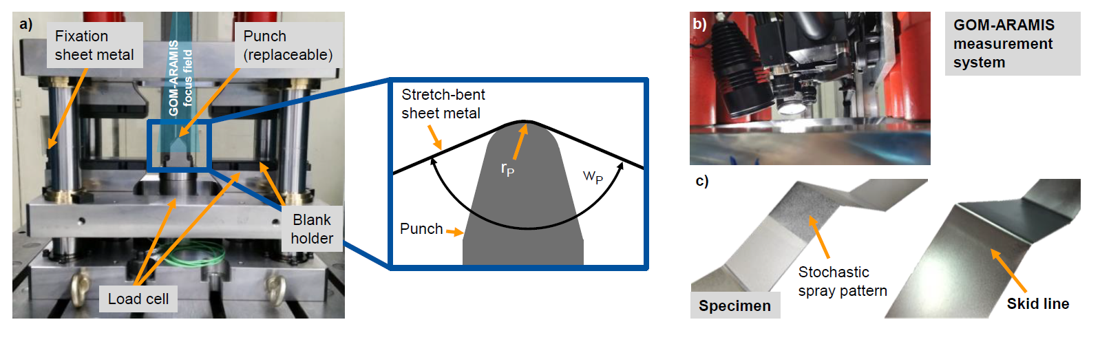
Fig. 2. Experimental setup.
(a) Showing experimental tool and process-related influencing factors, (b) GOM-ARAMIS and (c) deep-drawn specimen
Table 1. Material properties of DC06.
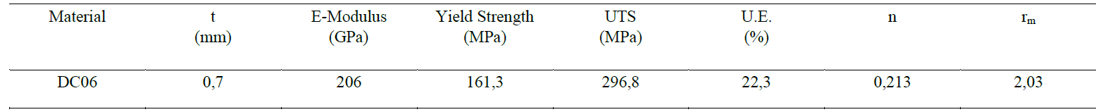
Table 2. Process parameters.

2.2 Results experimental study
After the experimental investigations, the surfaces of produced test samples were measured and digitized using an optical 3D surface measuring device shown in Fig. 3a) and b). Fig. 3c) shows the measurement result of two surface contours of the test samples. The red contour line represents a test sample with a skid line, the green line represents a test sample without skid line. The diagram shows that the skid line could be geometrically detected, which allows the offset of the skid line to be precisely determined. Afterwards, the resulting offsets and punch forces were correlated with the influencing factors blankholder force, punch radius rP and opening angle wP. Consequently, it was shown that the punch radius rP has a critical influence on the characteristics of the skid line due to the high contact pressure at the punch peak. This leads to an increase of the geometrical deviations in the area of the punch peak, as shown in Fig. 3c). An increasing blankholder force can also cause a critical contact pressure at the punch peak by preventing the sheet metal from being drawn-in. The outcome is an increase of the punch force due to the increase of the tensile stress in the test sample. However, a higher blankholder force can prevent skid lines, since it almost completely hinders the material flow in the blankholder area and therefore prevents the material from moving relatively over the punch radius. The opening angle wP influences the magnitude of the offset due to the drawing depth. However, this parameter does not provide any information about the formation of the skid line and has a small influence on its characteristic compared to the other influencing parameters. Based on the observations mentioned above, punch radius rP and blankholder force represent the main influencing factors on the formation of the skid line. Fig. 3d) shows that major strain measured by GOM-ARAMIS allows simple determination of skid lines.
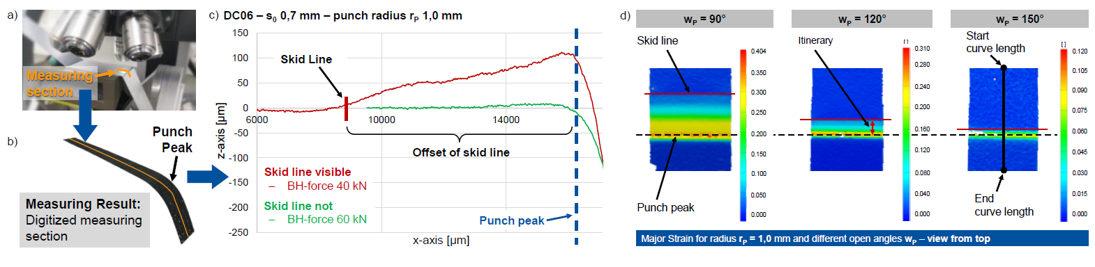
Fig. 3. Measuring results of contour and strains.
(a) Optical 3D surface measuring device for contour & roughness, (b) digitized measuring section, (c) contour of the surface of two specimens and
(d) GOM-ARAMIS measuring results: Major strain for specimens with three different opening angles wP
The FE simulation models described in the following were validated by determined strains, skid line offset, punching forces and the blank draw-in. With the help of these models, a criterion was developed to predict skid lines and evaluate them with regard to their quality relevance.
3 Modeling and numerical study
For the numerical study presented here, the experimental design described above was simulated; except for the variation of the opening angle wP. Due to its low influence on the characteristic of the skid line, the angle was kept constant at 120°. The modeling, simulation and evaluation was performed with the simulation software AutoForm R8. The FE model (Fig. 4a)) corresponds to the experimental tool shown in Fig. 2a) and consists of die, punch, blankholder and claw for fixing the sheet strip. The coefficient of friction was chosen with µ= 0.145 and the number of elements was 9423. In addition, the control parameter "Thickness Stress" was activated for all simulations. This parameter considers the pressure acting on the surface of the component caused by the reaction forces of the tools and the blankholder pressure. Consequently, material thinning occurs in the sheet metal plane in case of onesided contact with the punch. This effect is especially important when the material is bent over a sharp tool radius. As a result, higher local thinning occurs, which plays a significant role with regard to the formation of the skid line.
The results of the FE simulations of such forming processes were validated based on the experimentally determined parameters mentioned above, which proves the suitability of the FE model to represent the given process. With the help of these models the strain state variables unbending strain (ubs), thinning (thin) and major strain (ms) were numerically examined. The strain state variable ubs were calculated by subtracting the maximum curvature that an element has undergone until the current point in time from the current curvature of the element and then multiplying the result by half of the sheet metal thickness. Using this unbending strain ubs, the movement of the material over a tool radius can be determined, which gives an indication of a skid line but no information about its characteristics. For this reason, the strain state variable thin was considered, since thinning is very easy to detect and therefore it can provide an indication of the characteristics of the skid line. Based on the findings of the experimental investigations shown in Fig. 2d), major strain allows a simple detection of the skid line. Thus, the strain state variable ms was taken into account as well. Furthermore, it was expected that greater deformations lead to a more distinct skid line. Therefore, ms was used to draw conclusions about the characteristics of the skid line.
The investigation of the strain state variables ubs, thin and ms was carried out as shown in Fig. 4a) by placing a section in the FE-model over the area of the punch peak. The progression of each state variable at different blankholder forces and constant punch radius were overlapped as shown in Fig. 4b) and c). The grey and black curves each represent a sheet metal strip with a skid line, whereas the green curves show test samples without. Depending on the blankholder or retention force, which defines the material flow, skid lines can be created or prevented on the sheet metal strip.
Performed investigations showed that thin and ms can accurately detect the skid line for lower blankholder forces, as shown in Fig. 4b) using the example of ms. The grey curve shows a distinct progression at the curve length of 82 mm, which represents the skid line. However, this is not possible to achieve with higher blankholder forces because the difference between the black and green curve in the area in front of the punch peak appear almost identical. The strain state variable ubs shown in Fig. 4c), on the other hand, is able to detect the skid line at higher blankholder forces. Each curve shows a different maximum, by which they can be distinguished. Therefore, a limit value was set to detect the offset of the skid line. Based on the experimental results regarding the offset, this limit value was determined according to the test sample showing no skid line. The maximum of the curve of this test sample was used to determine the limit value for detection of the skid line. Nevertheless, ubs shows weaknesses in the exact prediction of the skid line for different blankholder forces and punch radii.
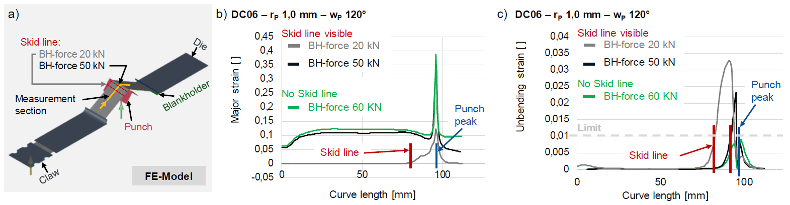
Fig. 4. Simulation results of the last forming step showing major strain and unbending strain curves.
(a) FE-Model, (b) major strain curve and (c) ubs-progression for three different blankholder (BH) force scenarios
4 Skid line criteria and results
Based on the findings of the numerical investigations performed, the strain state variables ubs, thin and ms were combined with each other. These combinations resulted in the criteria ubs²/thin and ubs²/ms, which can predict both the offset and the characteristics of the skid line. In Fig. 5a) and c) these criteria are shown for a punch radius rP of 1.0 mm. The limit value of 0.2 was determined in the same manner as explained for ubs. In order to evaluate the skid line with regard to its quality relevance to the component in the painted state, the test samples produced were cathodically dip-painted and a selection was additionally spray painted with black or silver metallic. After painting, 20 test persons were asked whether they could detect a skid line in the area of the punch peak. As a result, the majority of the test persons were able to detect all skid lines, which were also visible before the test samples were painted. It must be noted that skid lines near the radius, such as the skid line in Fig. 5b) at a blankholder force of 50 kN, indeed were difficult for the observer to recognize at all punch radii. Since the majority of the test persons recognized all existing skid lines, the limit value for both criteria did not have to be further adjusted. Further, the correlation of the criteria to the offset of the skid line also was examined. As a result, ubs²/thin achieved a regression model quality of 87% and ubs²/ms of 85%, indicating a high prediction accuracy of the criteria. In general, it is important to note that for the prediction of skid lines in terms of offset and characteristics, the FE model needs to be finely meshed (Master Element Size of 5.0 mm) in the area of the respective tool radius in order to obtain accurate results.
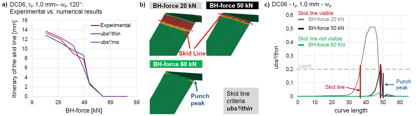
Fig. 5. Simulation results of the skid line criteria.
(a) Experiment vs. numerical results, (b) FE-Models with ubs²/thin-criterion, (c) ubs²/thin-progression for three different blankholder (BH) force scenarios
5 Conclusions and outlook
By the experimental and numerical investigations presented in this paper, two new evaluation criteria had been developed for determining the offset and the quality relevance of skid lines on sheet metal parts. For this purpose, experimental investigations with the material DC06 were carried out to investigate the process-related influencing factors of the formation of skid line and to determine a data basis for the subsequent numerical study. This study showed the correlation between the skid line and the strain state variables unbending strain, thinning and major strain. The combination of the mentioned state variables resulted into two skid line criteria, which showed a meaningful correlation with the offset of the skid line. Subsequently, the comparison of the numerical and the experimental results showed the predictability of the skid line by the presented evaluation criteria.
The developed evaluation criteria enable for instance the method planner to be supported at an early stage in the product development process. This is particularly important with regard to the design of deep-drawing tools for the production of outer skin components of a vehicle body. Since any skid line occurring in the component are visible to the customer and would therefore lead to scrap. The presented criteria now enable the method planner to predict quality-relevant skid lines already in the FEM simulation. Thus, necessary optimizations can be carried out on the tool before its production in order to avoid the occurrence of skid lines and the associated cost- and time-intensive reworking of the deep-drawing tool.
In future investigations, the developed criteria and their limit values will be analyzed regarding their transferability to other more complex component geometries. In particular, component geometries with A-symmetry and a multi-axial stress state during the deep drawing process will be considered. Moreover, concave and convex geometries should be taken into account for these parts, which can be found on structural edges or a tailgate of an automobile.
Acknowledgements
The Industrial Collective Research (IGF) project 19877N of the European Research Association for Sheet Metal Working (EFB) was funded via the German Federation of Industrial Research Associations (AiF). The authors like to acknowledge the European Research Association for Sheet Metal Working (EFB) for funding this project.
