1 Introduction
Cold forming offers various advantages, such as high strength, accuracy, surface quality, and optimum grain flow for an extended service life and cost-effective production. To fully exploit the process-specific advantages while considering ambitious geometries, several new forming strategies have been developed. One of these innovative processes is the free-divided-flow (FDF) process developed at IFU Stuttgart. Previous analyses and investigations have shown that the FDF process can be implemented to manufacture accurate face gears in a two-stage coining process. An additional process for manufacturing face gears was developed recently at the IFU Stuttgart that involves material predistribution: the “pin-to-gear” process. This process is based on the same operating principle as the FDF process. However, the pin-to-gear process requires a different material preform. This new material predistribution enables production of accurate face gears in a two-stage coining process with lower process forces compared to the FDF process or conventional coining. This paper describes the process principle of the new pin-to-gear process and compares it with familiar FDF processes before presenting a parameter study to determine preform parameters of the pin-to-gear process.
2 State of the Art
The conventional coining process has been known for many centuries. As early as 700 BC, King Croesus minted the first coin in Europe [1]. Since then, coining processes have always been used in mass production. Various studies have investigated the limits of the process both experimentally and numerically. P. Alexandrino [2], N. Nefissi [3], and C.J. Wang [4] show the strong increase in punch force near the end of the process. These studies determine the process limits of various coining processes in order to characterize the technological feasibility of the shapes produced. Unfinished form filling is one of the limiting factors of conventional coining processes, at the end of which almost the entire punch surface is in contact with the workpiece. This high level of contact causes friction, hinders the material flow, and increases the risk of damage to the die. Since the punch can only be loaded to a certain extent due to the risk of failure, the degree of die filling achieved is also limited. In this sense, the coining process is comparable with the face-gear forming process. Bogharov et al. [5], Thome et al. [6], and Ike [7] reported on investigations where the die filling of a coining process is quantified in terms of the completeness of the gearing geometry achieved. Complex workpieces have been manufactured primarily in multi-stage processes for many years in order to expand the forming process’ possibilities. Here, the material is predistributed in the first stages to obtain the desired geometry in the last stage. Whenever precise details are required, it is necessary to improve the material flow through a multistage process. J. M. Monaghan [8] was the first to recognize the importance of using a preform in a coining process. To reduce the high forces that occur at the end of the process, H. M. Monaghan and Ike [7] added a preform on the opposing side of the form elements to reduce the high forces at the end of the process. This increases form filling in zones where high pressure and high friction would otherwise occur. A new approach developed at the IFU Stuttgart for coining processes with preformed workpieces is called “free divided flow” [9]. In an initial forming process, the material is predivided such that the subsequent forming process results in a single-sided material flow into the cavities [10]. Tool load and surface pressure are significantly reduced, which improves the formability of complex components. These effects were verified through numerical and experimental investigations [11].
3 Process Characteristics
In order to describe the pin-to-gear process, a detailed description of mold filling during the conventional coining process will be described, contributed geometric tool parameters defined, and a methodology developed. Furthermore, a hypothesis is made, the application of which will be demonstrated with the pin-to-gear and FDF processes. All diagrams shown in this chapter are numerically generated. The simulation parameters can be obtained from the subsequent section Simulation Setup (4) and the parameter study for the pin-to-gear process (5).
3.1 Gear forming by means of conventional coining process
A short punch stroke and increased punch forces toward the end of the process distinguish coining processes. These high punch forces are caused by the large punch–workpiece contact area and low degree of material flow. As a result, the gear geometries manufactured with coining processes are considerably limited. Figure 1 illustrates an example of the relationship between the projected vertical punch–workpiece contact (e.g.: for a round punch with molds and 50% punch–workpiece contact, this equals 0.5⋅πr2) and the mean punch stress (punch force divided by punch cross-section area, e.g.: F/πr2) for identical gear dimensions with differing total widths (further referred to as gear density = (zone A/zone B)⋅100, e.g.: zone B = 2⋅zone A gear density 50%). Up to a vertical punch contact of 90%, all three curves follow a similar trend, which is indicated with a dashed gray line. However, if a vertical punch contact of more than 90% occurs, the mean punch stress increases disproportionately for low tooth densities (see coining density 25% in Figure 1). Furthermore, the trend line deviates for low tooth density at the start of the coining process. However, this results from a high initial vertical punch contact. Figure 1 illustrates the high punch stresses in conventional coining processes with low tooth density.
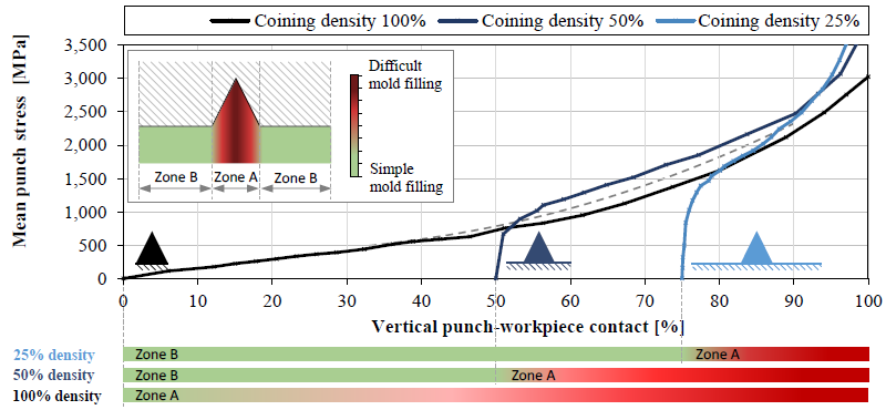 Figure 1: Mean punch stresses in the conventional coining process and classification of punch contact zones
In order to develop a general approach, the total gearing has been subdivided into different zones. Zone B areas are already in contact with the punch at the beginning of the process. Zone B therefore indicates areas in which the punch contour can be applied to the workpiece without difficulty. Conversely, zone A represents segments that are difficult to form. In zone A, the mold forming difficulty diverges significantly from the tooth root to the tooth tip. For illustration purposes, a sample tooth has been divided into zones in the image in Figure 1. Qualitatively speaking, the mold filling difficulty between the tooth root and tip is indicated. Below the diagram in Figure 1, the mold filling difficulty for three tooth densities is shown in a bar chart specific to the vertical punch– workpiece contact. Conventional coining processes initially form areas in zone B and subsequently in zone A. Therefore, the tip of the tooth (which is the most challenging to form) is not formed until the end of the process. Since the vertical punch contact is already high at the end of the process, the punch stresses will likewise be high.
3.2 Gear forming using a preform
Based on the method of dividing the workpiece into zones as described in Figure 1, the following theory is proposed:
If the punch–workpiece contact in zone A (tooth tip) is provided before the contact in zone B (tooth root) high mold filling can be achieved with low process forces.
In order to use the postulated process advantages, material predistribution is required prior to gear forming. An additional forming operation is necessary to manufacture this preform. The objective of the preform design is to ensure a material flow such that zone A is formed prior to the complete filling of zone B. Therefore, the material must be predistributed in either zone A or in a section of zone B. Two processes have been developed with a specific preform geometry and respective fields of application: free-divided flow (FDF) and pin-to-gear. Figure 2 illustrates the intended material predistribution for both processes in comparison with a conventional coining process. Conventional coining shows an initial punch–workpiece contact in zones B1 and B2, the FDF process only in B2 (in some designs additionally in zone A) and the pin-to-gear process in a section of zone A.
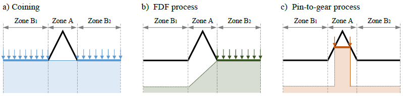 Figure 2: Comparison of the punch contact for gear forming with different preforms; a) coining reference process, b) FDF process, c) pin-to-gear process
The correlation between mold filling and punch load in the defined processes is shown in Figure 3. Analogous to the notation introduced in Figure 1, the zone filling sequence is illustrated in a bar chart below Figure 3. In the pin-to-gear process, zone A is formed first. Consequently, the gearing is already completely filled at a vertical punch contact of 25%. In the subsequent process, only a minimal increase in the mean punch stress occurs. In the FDF process, the punch–workpiece contact is initially achieved in zone B2, subsequently in zone A, and finally in zone B2. Due to this material flow, the FDF process shows a slightly increased maximum punch stress compared to the pin-to-gear process. However, the maximum punch stress of the FDF process is significantly lower than that of the conventional coining process. In this example, a maximum punch stress of 500 MPa occurs in the pin-to-gear process and 1,200 MPa in the FDF process. In conventional coining, a punch stress above 3,500 MPa occurs at the end of the process. The high punch stress results in a high tool load and can lead to material fractures. Early forming of critical zone A areas thus facilitates a significant reduction in punch stress.
 Figure 3: Comparison of the mean punch stresses of the pin-to-gear, FDF, and conventional coining process alongside illustration of the zone filling sequence
According to the previously described effects, the punch stress in the pin-to-gear process is always lower than in the FDF process. However, these investigations show only the gear forming process and not preform forming. Here, a conventional coining process is used (see Figure 4). The trend line of conventional coining (see Figure 1) is plotted in gray. The preforms of both processes do not require complete mold filling. Therefore, the punch stress is significantly lower compared to a conventional coining process for gear production. To manufacture the pin-to-gear preform, a significantly higher punch–workpiece contact is required than for an FDF preform. As a result, the mean punch stress is considerably lower in the production of the FDF preform. This enables the field of application to influence both processes. The FDF process is well suited for extremely low gear densities, whereas the pin-to-gear process is suitable for high to medium gear densities and extreme gear geometries due to the low process forces.
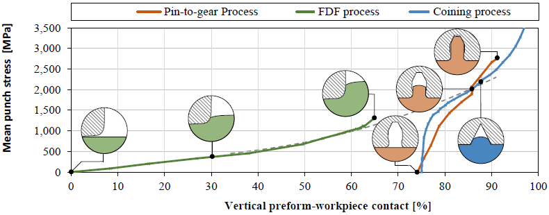 Figure 4: Mean punch stress in the pin-to-gear and FDF preforming process compared to the conventional coining process
4 Simulation Setup
In order to conduct an initial numerical investigation into the pin-to-gear process, a simulation was set up in DEFORM 2D. This simulation consists of two successive, interlinked forming stages. Figure 5 illustrates the workpiece of the simulation setup. The examined toothing has a width (B) and height (H) of 2 mm. Total width measures 8 mm, which results in a tooth density of 25%. The radii are 0.1 mm. Including the radii, the toothing comprises a volume of 1.75 mm3 (V0). The material 16MnCr5 [12] was used, and the simulation was conducted in plane-strain mode. Die filling was examined at two positions: zone A die filling and overall die filling. The aim of the examination was to avoid underfilling in zone A and prevent folds at the tooth root (constraints). The hybrid friction model was used with a friction factor of 0.12 coulombs and 0.06 shear. The initial temperature was set to 20 °C. Figure 5b shows the preform during the tooth forming process. The mesh consists of 4,200 elements with a mesh refinement at the tooth root. A numerical design of experiments study (DOE study) and optimization study (OPT study) were conducted. Tooth parameters remained constant. This DOE study consisted of 50 simulations in which the parameters were determined using the statistical Latin Hypercube (LHC) method. The objective of this study was to determine the influence of the preform parameters on the forming process. The subsequent OPT study consists of 55 simulations. The aim of this investigation was to optimize the identified geometrical parameters in order to achieve high mold filling without folds and with a low forming force.
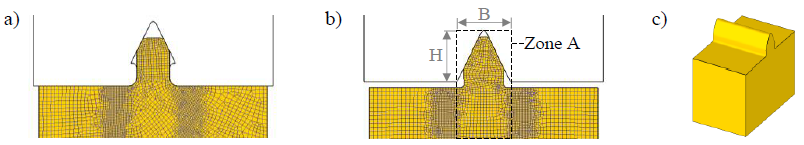 Figure 5: Simulation setup for pin-to-gear process; a) first stage – pin-to-gear preform; b) second stage – gearing; c) 3D illustration of the examined workpiece
5 Parameter Study for the Pin-to-Gear Process
Figure 6 contains the results of the iterative preform design, which was conducted prior to the initial DOE study, the objective of which was to obtain a preform design consisting of a limited number of parameters. Figure 6a illustrates all selected geometrical parameters to define the preform design. These comprise three geometrical parameters (HV, BV, RV) and the volume of the material that is molded into the preform (VV). To prevent misalignment between the two forming stages, a specific preform shape was designed. This preform consists of a defined contact surface for orientation in the subsequent forming stage that is located on the tip of the preform (see Figure 6a). Figure 6b shows the forming of the toothing out of the preform in three steps. The last figure (Figure 6b```) shows examples of tooth defects. The tooth tip exhibits an underfill, and the tooth root exhibits a fold. The objective of the investigation is to identify geometrical parameters of the preform that result in failure-free forming of the tooth and also apply minimized process forces in the second forming stage.
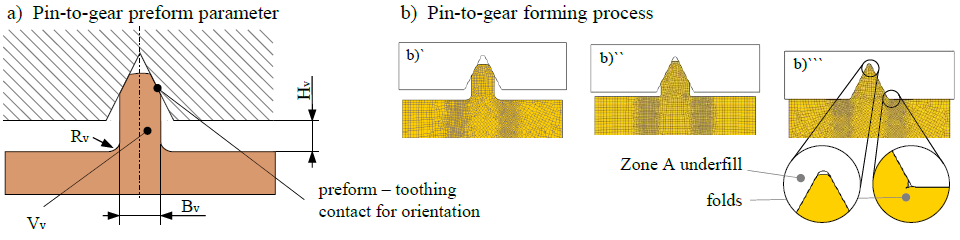 Figure 6: Setup of the parameter study; a) selected preform parameters, b) pin-to-gear forming process with potential defects
Figure 7a) displays the results of the DOE study in two tornado diagrams. These diagrams indicate the impact of the geometric input parameters on the process output parameter (process force). The bar height illustrates the relevance of the individual parameters for the resulting process force in the second forming stage. The difference between the two diagrams is that the diagram on the right (Figure 7a´´) excludes simulations that do not fulfil a constraint (folds or zone A underfilled). Based on these diagrams, it is obvious that all selected parameters have an impact on the gear forming process. Parameter RV shows a unique characteristic in the evaluation, since this parameter has a large effect in Figure 7a´ and an insignificant effect in Figure 7a´´. As a result, parameter RV is almost identical in all simulations without defects. Therefore, parameter RV is set as constant in the identified field of application for future investigations. The simulation results of the OPT study in relation to the maximum punch force are displayed in Figure 7b. Initially, two LHC simulation studies were performed with a restriction of the parameter scope by 25%. The parameter sets with the lowest punch force were subsequently optimized using the gradient method. The colors indicate whether or not the constraint was fulfilled. All simulations that fulfill all constraints are indicated by a green dot. The simulation with a green dot and the lowest punch force thus represents the best parameter set of the study. Figure 7c shows the optimized parameter set for the OPT study. The identified parameters were related to the gearing parameters (H; B) in order to use them for future preform design.
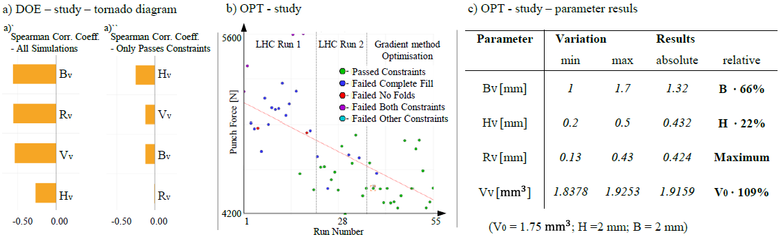
Figure 7: Results of the DOE and OPT study; a) tornado diagram – preform parameters; b) procedure of the OPT study; c) parameter results OPT study
6 Summary and Outlook
The process-specific characteristics of the coining process include a short stroke, high process forces, and large-scale punch– workpiece contact. Using the conventional coining processes, the difficult-to-shape elements are filled until the end of the process is reached. Based on this, the following hypothesis was formulated: If the punch–workpiece contact at the tooth tip is provided before the contact on the tooth root, high mold filling with low process forces can be achieved. The hypothesis led to the development of a new process: the “pin-to-gear” process. With this process, the material is predistributed using a preform. This preform is pin-shaped and located in the same position as the subsequently formed toothing. In comparison, the FDF process predistributes the material beside the gear teeth, resulting in a lateral material flow into the cavity during the second forming stage. The new pin-to-gear process was investigated through a linked numerical simulation. A comparison was made between the pin-to-gear process, the FDF process, and a conventional coining process. The pin-to-gear process has demonstrated significant advantages in terms of the required process force, occurring stresses, and contact pressures. The most significant benefit of the novel pin-to-gear process is its ability to fill tall tooth geometries with significantly reduced process forces. A parameter study was conducted to determine appropriate preform parameters. It was possible to identify a valid parameter set with four parameters and to optimize these in a numerical study. In this paper, the advantages of the pin-to-gear process and the field of application have been demonstrated. Based on the developed methodology, preform geometries for other types of gearing can be developed. Leading on from these studies, a tool for validating and verifying the simulated results will be designed. Furthermore, the possibility of using the pin-to-gear method for producing conventional involute gears will be investigated.
