1. Introduction and State of the Art
The final part-contour of deep drawn sheet metal components is usually produced by shear cutting operations. Due to the geometry of these components, however, cutting operations often have to be performed in a non-perpendicular state (s. Fig. 1). Such processes are referred to as punching with slant angle, if angle β between the sheet surface and the horizontal is greater than 0° [2].
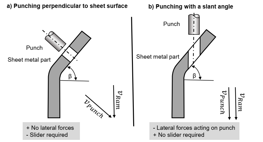
Fig. 1: Punching perpendicular to sheet metal component surface (a) and punching with a slant angle (b) according to [1]
According to the state of the art, maximum slant angles in stamping technology are usually conservatively estimated. Since generally valid tool design criteria do not exist for punching processes with a slant angle, expensive sliders are used today for most punching operations with slant angles. As experimental and numerical investigations of the research project [3] have shown, even the high-strength sheet metal material DP1000 can be reliably punched (no punch breakage) with a punch diameter of 5 mm for a sheet metal thickness of 1 mm up to a slant angle of 17.5°. In contrast, according to today´s conservative process design, a slider would already have been used at a slant angle of 5° [4]. In order to reduce the use of expensive sliders and thus to achieve cost-saving potentials in production, the cutting surface characteristics achievable at punching with a slant angle must additionally be predictable. According to the current state of the art, however, the cutting surface characteristics such as edge draw-in, clean cut, fracture surface and burr formation are almost unknown for punching with a slant angle.
Due to the inclined position of the sheet metal component during punching with a slant angle, an asymmetrical characteristic of the cutting surface parameters such as edge draw-in, clean cut, fracture surface and burr occurs along the hole circumference. In this respect, Fig. 2 shows the result of a numerical 3D punching simulation to illustrate this effect.
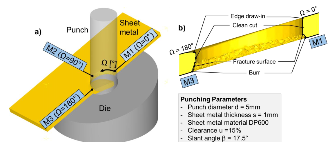
Fig. 2: Definition of measuring positions (a) and asymmetrical characteristics of cutting surface (b)
The measuring positions M1, M2 and M3 marked in Fig. 2 show that especially on the side of the punch entry (M1; Ω = 0°) and on the side of the punch exit (M3; Ω = 180°) larger differences between the edge draw-in heights, clean cut heights, fracture surface heights and burr heights occur. Stamping process planners must be aware of these cutting surface characteristics when designing punching processes with a slant angle. Against this background, the experimental test results presented in the following sections show that a regression model-based prognosis of cutting surface parameters is possible for punching with a slant angle, thus opening up new possibilities for a more cost-effective design of punching tools.
2. Experimental Process Analysis
2.1 Punching tool and investigated punching parameters
The experimental investigations reported about in this paper were performed using a modular punching tool. In this punching tool, the punches were precisely guided in the part holder in order to avoid any horizontal punch deflections due to lateral forces. The modular design of the tool allows a variation of the slant angle by exchangeable mounting plates. For the experimental process analysis, mounting plates with slant angles of 0° (normal cutting), 10°, 12.5° and 17.5° were used.
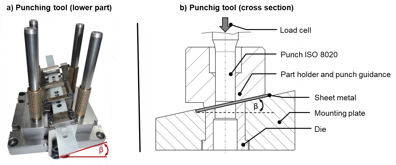
Fig. 3: Modular punching tool (a) and cross-sectional view of the punching tool (b)
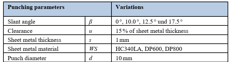
Table 1 provides an overview of the punching parameters investigated in the experiments conducted. Furthermore, the highstrength sheet metal materials HC340LA (1.0548), DP600 (1.0936) and DP800 (1.0943) were chosen as materials to be examined, since they are frequently used for automotive lightweight applications. The investigated sheet metal thickness of 1mm also corresponds to sheet metal components being used in modern car bodies. Experimental investigations were performed with a punch diameter of d = 10 mm. The cutting edges of the cutting punches (according to FISO 8020) as well as those of the dies were manufactured sharp-edged, resulting in a relatively small cutting edge rounding of about 5 µm. Experiments were carried out in single stroke testings with 3 repetitions for each parameter variation. The cutting speed of 100 mm/s was chosen in accordance to automotive applications.
Table 1. Experimentally investigated punching parameters
The tensile strength of the sheet metal materials used was determined by uniaxial tensile tests according to DIN EN ISO 6892.
Table 2 shows a summary of these experimentally determined material data.
Table 2. Sheet metal materials HC340LA, DP600 and DP800 – material data

In addition to the tensile tests, conventional shear cutting experiments (β=0°) were carried out to experimentally determine the sheet metal material specific shear resistance by equation (1).

The size of clearance was determined using the analytical method proposed by Dietrich [5]. According to equation 2, this results in a suitable clearance size for the sheet materials HC340LA, DP600 and DP800 ranging between 12.0% to 15.5% of the sheet thickness.

Due to the slight differences between the analytically calculated clearance sizes, a constant clearance of u = 15 % was chosen for the subsequent experimental process analysis.
2.2 Analysis of cutting surface characteristics
An Alicona digital microscope was used for the analysis of the cutting surface characteristics obtained during the experiments concerning punching with a slant angle. The digital microscope is equipped with a servo-driven specimen holder, which allows a highly precise and non-destructive digitalization and measurement of the shear-cut sheet metal samples. The evaluation of the cutting surface contour was performed by defining auxiliary planes as shown in yellow in Fig. 4(b)
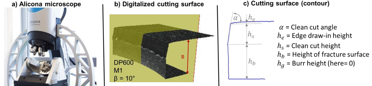
Fig. 4. Alicona microscope (a), digitized cutting surface (b) and cutting surface contour (c)
On the conventionally (β=0°) punched sheet metal samples, a clean cut angle of α = 90 ° was measured for all investigated sheet metal materials. When punching with a slant angle, the clean cut angle deviated from 90° due to punching on inclined surfaces. The measurements of all punched sheet metal samples showed that the clean cut angle at the measuring positions M1 (first sheet contact of the punch) and M3 (last sheet contact of the punch) can be calculated with the following equations.
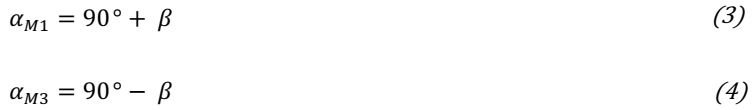
Table 3 shows the cutting surface contours determined for the sheet metal materials HC340LA, DP600 and DP800 at the measuring positions M1 and M3. The black dots in table 3 do characterize the typical transition points between the edge draw-in height, the clean cut height, the height of the fracture surface and the burr height. The cutting surface contours shown in table 3 illustrate typical cutting surface tendencies for punching with a slant angle. At measuring position M1, the edge draw-in height significantly decreases when increasing the amount of slant angle. Furthermore, an increase of the clean cut height can be determined for an increasing size of the slant angle. The height of the fracture surface decreases as the slant angle increases. At measuring position M3, the edge draw-in height increases for all investigated sheet metal materials. In contrast, the clean cut height and the fracture surface height exhibit a more complex nonlinear behavior with increasing and decreasing tendencies. Table 3 also shows, that the burr height decreases with an increasing size of slant angle at both measuring positions.
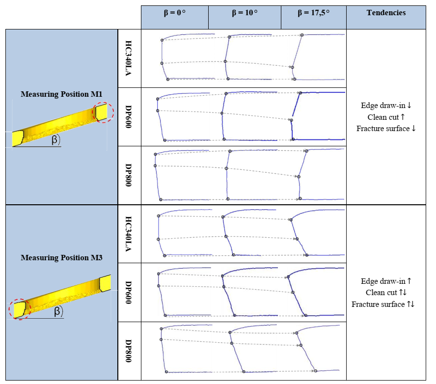 Table 3. Experimentally determined cutting surface contours for the sheet metal materials HC340LA, DP600 and DP800
In order to quantify these tendencies, a regression analysis was performed based on the experimentally determined cutting surface data (black points).
2.3 Regression models for punching with a slant angle
The evaluation of the measured cutting surface parameters was performed using the response surface method. For this purpose, the black points, which define the typical cutting surface characteristics (s. Table 3), were analyzed by the use of the statistical evaluation software “Minitab” for investigated sheet metal materials. For this purpose, the experimentally determined data points were plotted in the first evaluation step and thus a corresponding point cloud was created. This point cloud is shown in Fig. 5 as an example of the measured edge draw-in heights at measuring position M1. In this example, the edge draw-in height is given as a relative proportion of the investigated sheet thickness of s = 1 mm (= 100%). For the development of a predictive regression model from this point cloud, a suitable interpolating spline parameterization of this hypersurface had to be found in the second evaluation step.
 Fig. 5. Cloud of experimental data points (a) and regression model with response surface, coefficient of determination 𝑅2 and statistical variance s (b)
For the interpolation between the data points, second-degree polynomials were chosen as regression models. These fitting functions allowed a sufficiently precise approximation of the hypersurfaces to the experimentally determined data points with a coefficient of determination 𝑅2 higher than 90%. The general mathematical formulation of the chosen hypersurface plane equations is given in equation (5). The factors A, B, C, D, E and F represent empirical constants.

Fig. 6 shows an overview of the determined regression models, hich quantify the cutting surface parameters edge draw-in heigth, clean cut height and fracture surface height at the measuring position M1. It can be seen that the edge draw-in height significantly decreases with an increasing amount of the slant angle for all investigated sheet metal materials. Furthermore, an increase of the clean cut height can be observed with increasing slant angle. With regard to the height of the fracture surface, no significant increase or decrease can be recognized for the sheet material HC340LA having a comparatively low shear resistance. In contrast, higher shear resistances (DP800) result in a decrease of the fracture surface height. For the sheet metal materials DP600 and DP800, no (measurable) cutting burr heights were detected at measuring position M1, when the amount of the slant angle exceeds a value of β=10° (also see Fig. 4(c)). Fig. 7 contains an overview of the regression models, describing the experimentally determined cutting surface contours at the measuring position M3. It can be seen that the edge draw-in height at the measuring position M3 increases slightly with an increasing amount of the slant angle. The (non-linear) relationship between the clean cut height and the slant angle (also see table 3) was confirmed for each investigated sheet metal material. Accordingly, the hypersurface provides a corresponding low point at β=10°. At measurement position M3, fracture surface heigth was measured inversely proportional to the hypersurface of the clean cut height. For the sheet metal materials DP600 and DP800, no (measurable) burr heights could be detected at measuring position M3, when the amount of the slant angle exceeds β=10°. The cutting surface parameters at measuring position M2 did not depend on the amount of the slant angle. Edge draw-in height, clean cut height and the height of the fracture surface correspond in good approximation to the values under conventional cutting conditions (β=0°). Equation (5) and the constants given in Fig. 6 and Fig. 7 provide a novel analytical calculation approach for the determination of cutting surface contours when punching with a slant angle. Since the requirements for shear cut sheet metal component edges can vary considerably in industrial practice, method planners often have to decide in advance for each individual sheet metal component whether the holes can be punched at a certain degree of slant angle. Punched holes must fulfill requirements regarding functional surfaces or the feed-through of cable and line systems. Since no measurable cutting burr could be detected in the punched holes (DP600 & DP800, β > 10°), interesting possibilities arise for cable routings. Thus, in the case of conventional punching, the burr often has to be removed mechanically at great manufacturing costs in order to avoid possible cable damage due to sharp-edged burrs. Another possible application of holes punched with a slant angle is to center a punched component for subsequent joining operations. The comparatively high clean cut portions can be useful in the sense of a functional surface for the precise centering and alignment of sheet metal components. Therefore, RPS-holes might be a possible application of punching with a slant angle. Due to the simple tool design, the exact hole position can also be precisely implemented and, if necessary, corrected with comparatively low effort when punching in press working direction [4]
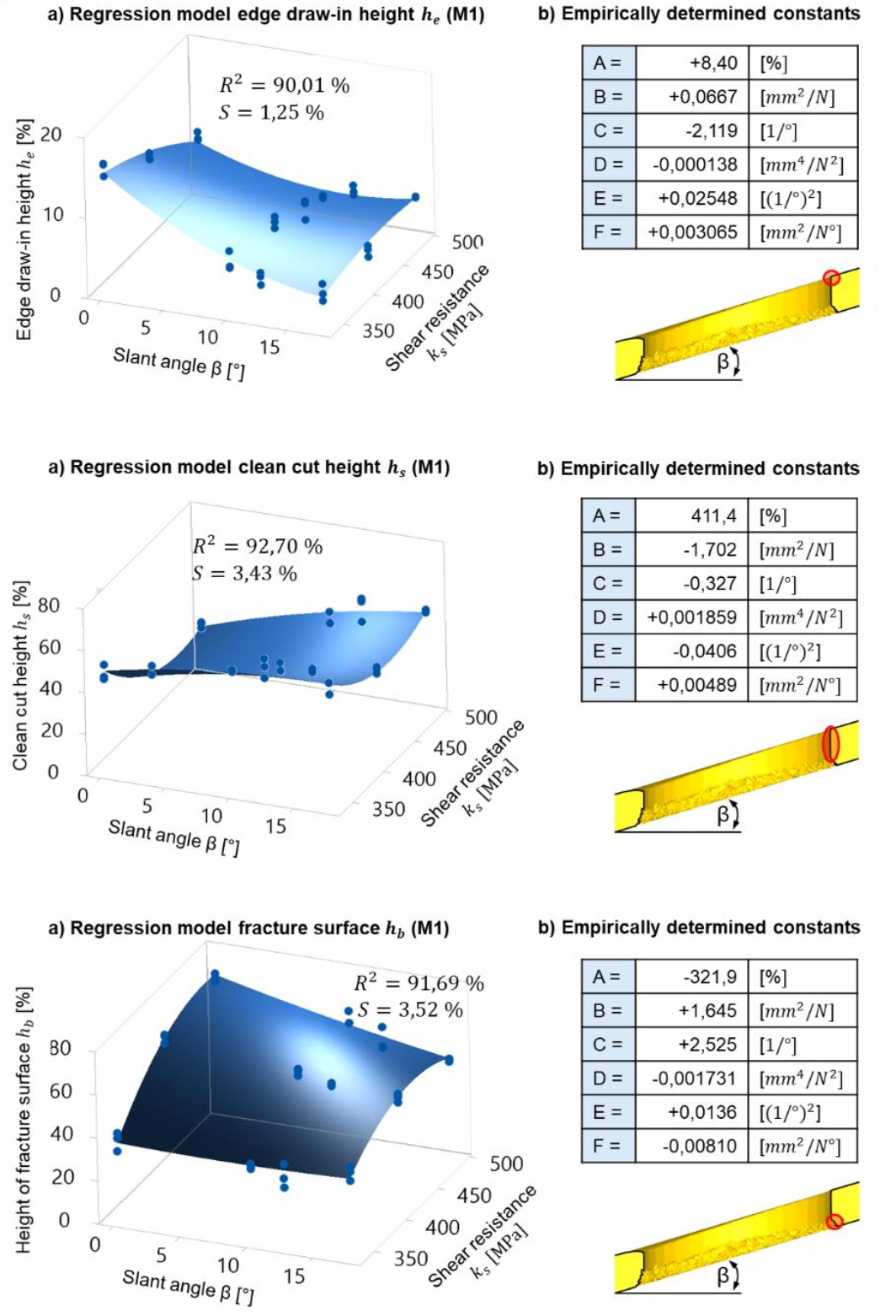 Fig. 6. Regression models for measuring position M1
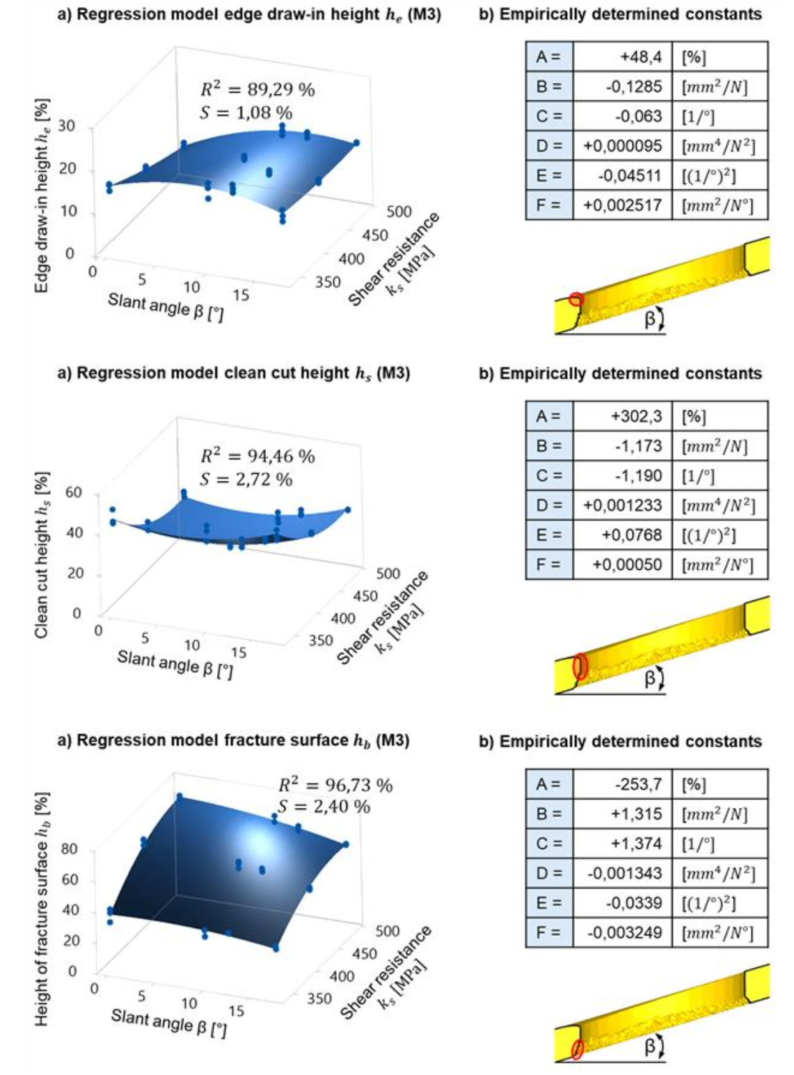 Fig. 7. Regression models for measuring position M3
With the regression models in Fig. 6 and Fig. 7 and the empirical constants given, a quantification of cutting surface parameters for punching with a slant angle is now available for the first time. Future research at IFU Stuttgart concerns further experimental and numerical investigations in order to extend the presented regression models. Since a 3D simulation model is required for a corresponding numerical process analysis [7], the precise numerical calculation of the cutting surface parameters remains still as an unsolved problem for punching with a slant angle. As Fig. 8 shows, the presented regression models can be used for the calibration of punching simulations using the simulation software DEFORM 3D and the fracture model “normalized Cockroft & Latham”.
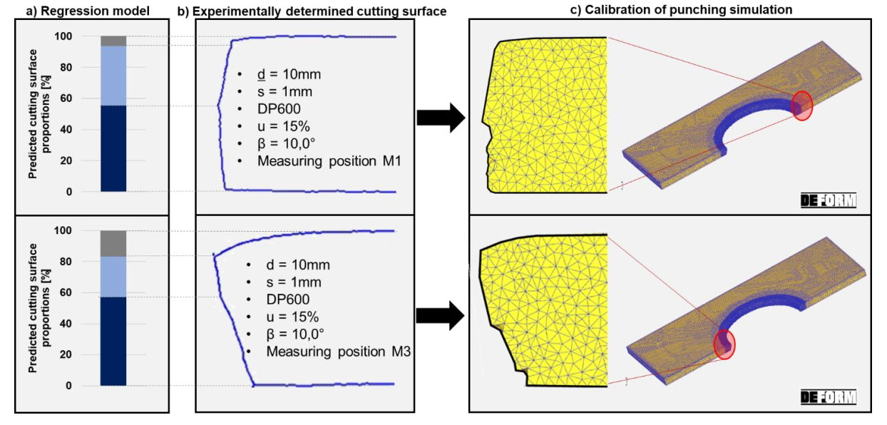 Fig. 8. Predicted cutting surface proportions (a) experimentally determined cutting surface (b) and calibration of punching simulation (c)
According to the current state of numerical research at IFU Stuttgart, similar cutting surface contours for different punch diameters can be expected. This numerical transfer to further (deviating) punching parameters will be validated in further research work.
3. Summary and further research
For economic or process-related reasons, punching of structural sheet metal components often has to be performed with a deviation from the optimum angle of 90° between sheet metal and punch. This angle difference is referred to as “slant angle”. However, at the current state of the art, no precise information was available on the characteristics of cutting surfaces when punching with a slant angle. This paper contains an empirical test series for the characterization of cutting surface parameters when punching with a slant angle. The research results showed an asymmetric characteristic of the cutting surface contour along the hole circumference of punching line. However, the sheet metal materials HC340LA, DP600 and DP800 showed recurring tendencies with regard to the cutting surface contour. These tendencies could be quantified by 3D- regression models. With these regression models, stamping process planners can make prognostic statements regarding the cutting surface contour to be expected when punching with a slant angle. Another advantage of the determined regression models is, that they can be used for the calibration of complex numerical punching simulation. Future research at IFU Stuttgart will focus on further investigations regarding the transferability of the regression models determined so far. For example, the punching parameters sheet metal material, sheet metal thickness, punch diameter, punch guidance or punch wear are to be varied experimentally and numerically in order to extend the regression models presented here.
