1 Introduction
The Ti6Al4V one of the most widely used titanium alloy. The machining of this expensive alloy remains a major production industry concern because of the poor machinability characteristics. The Finite element modelling is widely employed by researchers [1] to reduce the experimental costs. Due to many factors that affect the machining, the finite element modelling of machining is a very complex process, often limited to the simplified orthogonal cutting configuration. Therefore, a well-defined flow stress model that considers the strain, the strain rate, the temperature, the hardening, the viscosity, and the loading history of the material is necessary in numerical modelling of metal cutting process. Dependency of the results to cutting parameters (and especially cutting speed) are important factors in determining machinability behaviors in addition to mechanical properties of a workpiece. A definitive constitutive model is always a principal factor in developing a finite element model [1]. Many material constitutive models have been developed in the recent years. Because of their simplicity and lucidity empirical models are widely considered.
The aim of this work is to investigate the influence of cutting speed ranging from 30 m/min to 75 m/min on forces and chip morphologies of Ti6Al4V alloy. This paper compares and analyze the finite element simulated results from Johnson-Cook model [2], the modified Johnson-Cook model from Calamaz et al. [3] that takes the strains softening behavior into account and the Modified Johnson-Cook from Hou et al. [4] that takes into account temperature dependent hardening factor and its coupled effects between strain and temperature with the experimental work carried out by Ducobu [5] for the cutting speeds of 30 m/min, 50 m/min, 75 m/min. The forces and chip morphologies from the nine simulations are compared and are validated with the experimental results.
2 Numerical Modelling
2.1 Material Constitutive Models
The empirical or phenomenological constitutive models are considered by many researchers for their simplicity and robustness. These models consider the variables of deformations such as the plastic strain ɛ, plastic strain rate ɛ̇, and temperature 𝑇 under macroscopic scale.
2.1.1 Johnson–Cook Constitutive Model (JC)
The most widely used thermo-mechanical model that links plastic, viscous and thermal aspects observed during orthogonal machining process is the popular Johnson-Cook model [2]. Its flow stress is expressed by the following Eq. (1):

Where 𝐴, 𝐵, 𝐶, 𝑛, 𝑚 are the constants that depend on the material and are determined by material tests. 𝐴 is the yield strength, 𝐵 the hardening modulus, 𝑛 the strain-hardening exponent, 𝐶 the strain rate sensitivity and 𝑚 is the thermal sensitivity. Constants 𝐵 and 𝑛 report the strain hardening. 𝑇𝑚𝑒𝑙𝑡 and 𝑇𝑟𝑜𝑜𝑚 are the melting temperature and the room temperature respectively, while ɛ̇0 is the reference strain rate. The parameters for this model are given in Table 1.
The JC model is meaningful in certain operating ranges of strains and strain-rates (strains up to 0.5 and strain rates lower than 104 s−1) [1] but fails to capture high strain material behavior in machining, where the flow stresses are difficult to measure by existing material testing devices [2].
Thermal softening is defined as the flow stress drops with the increased temperature regardless of plastic strain. JC model does not account for softening observed at the strains and temperatures in the primary shear zone, which is characteristic of metals that exhibit shear banding [1]. This leads to modified or updated versions of Johnson-Cook model.
2.1.2 Modified Johnson–Cook model by CALAMAZ (JC-Calamaz)
A Modified version has been suggested by Calamaz et al. [3] by introducing a hyperbolic tangent (TANH) term into the Johnson-Cook flow stress model to incorporate strain softening effect at the high-speed machining process. The material flow stress for TANH model is expressed by the following Eq. (2):
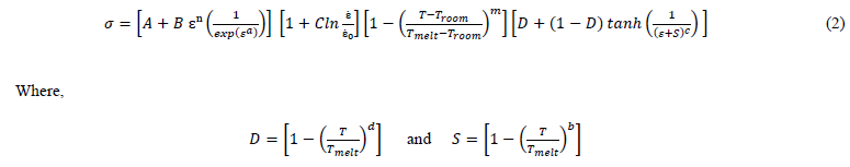
Parameters 𝐴, 𝐵, 𝐶, 𝑛, 𝑚 have the same meaning of JC model and the new constants 𝑎, 𝑏, 𝑐 and 𝑑 are introduced by TANH law. The parameters for this model are given in Table 1. In the above equation, the first term, strain hardening function is modified by including flow softening at higher strain values, the second term on strain rate and the third term on thermal softening function remains unaltered and a fourth term on temperature-dependent flow softening condition were added.
2.1.3 Modified Johnson–Cook model by HOU (JC-Hou)
A temperature function into the work hardening term was introduced by Hou et al. [4] to describe the phenomenon of temperature dependent hardening effect for better prediction of flow stress behavior of Ti6Al4V alloy under loading condition of high strain rate and temperature. By coupling logarithmic strain hardening rate and thermal sensitivity coefficient along with the strain function a modified JC model was proposed (Eq. 3) by Hou et al.
The flow stress equation is expressed by the following Eq. (3)

Where, 𝑚1 is the thermal sensitivity coefficient with the increasing strain, and the rest of all parameters have the same meaning as JC model. The authors concluded that strain hardening rate of Ti6Al4V alloy has no noticeable strain rate sensitivity but evidently temperature sensitivity. The parameters for this model are given in Table 1.
Table 1. Parameters adopted for JC model [6], JC-Calamaz [3] and JC-Hou [4]
![Table 1. Parameters adopted for JC model [6], JC-Calamaz [3] and JC-Hou [4]](docannexe/image/2424/img-4.png)
The stress vs strain curve evolution for the JC, JC-Calamaz and JC-Hou at fixed temperatures of 𝑇=573 K and 𝑇=973 K for strain rate of ɛ̇=10000 s-1 is plotted in Fig 1.
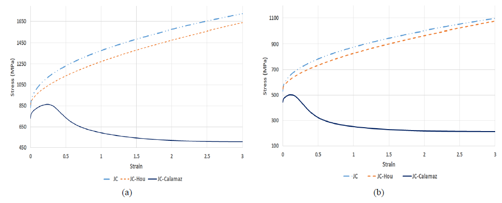
Fig. 1. Stress-strain curves of JC, JC-Calamaz and JC-Hou (a) at 𝑇=573 K and ɛ̇0 = 10 000 s-1 (b) at 𝑇=973 K and ɛ̇0 = 10 000 s-1 [7]
By comparing the stress-strain evolution curves in Fig.1 it is revealed that JC law, JC-Calamaz law that includes softening behavior and the JC-Hou law that consider temperature dependent hardening effect shows a significant difference in the evolution of stress with respect to strain at high temperature and strain rate. It is significantly important to note that the initial stress value of JC-Calamaz is very low when compared with initial stress value of other two constitutive models considered in this study. This might influence the calculation of forces and chip morphology.
2.2 Finite Element Model and Cutting Conditions
The finite element model (including information on damage model and friction conditions) was adopted from previous authors’ work [6]. Tungsten carbide is selected as a tool material and the tool geometry is defined by the rake angle of 15°, the clearance angle of 2° and the cutting edge radius of 20 μm for cutting condition of uncut chip thickness of 60 μm with different cutting speeds of 30 m/min, 50 m/min and 75 m/min which makes a total of nine models.
3 Experimental reference
The experimental reference is considered from the work of Ducobu [5]. The author adopted plunge turning conditions on a lathe to fulfill the hypotheses of the orthogonal cut with a lathe. This allows to evaluate the influence of the cutting speed. The cutting conditions are the same as for the simulations. Tungsten carbide tool is employed for machining of Ti6Al4V alloy. Three repetitions for each cutting speed were performed. The forces were measured with a dynamometer (Kistler 9257B), and useful part of the signal during cutting operation is considered to compute the RMS value of forces. The experimental setup is shown in Fig. 2.
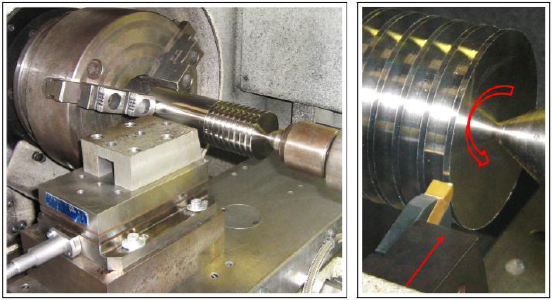 Fig. 2. Experimental setup [5]
Although segmented chips are often formed when machining Ti6Al4V, continuous chips were observed from the experiment. This is due to the rather low feed value of 60 μm/rev. The RMS values of cutting force (FC), Feed force (Ff) and chip thickness (h’) are given in Table 3.
4 Numerical Results
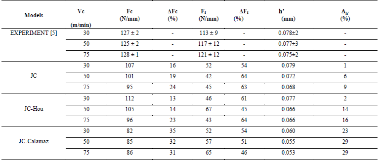
Initially numerically simulated chips from JC and JC-HOU model with cutting speeds of 30 m/min, 50 m/min, 75 m/min are investigated and compared in Fig 3 and Fig 5. All the numerical chips are continuous as expected and the chip thickness decreases with increase of cutting speed for both JC and JC-Hou. The temperature distribution at the deformation zone is analyzed. As expected, the temperature is maximum in the secondary deformation zone for all three cutting speeds in the order of 75 m/min > 50 m/min > 30 m/min. The RMS forces values are calculated and compared in Table 2. It was observed that the magnitude of the cutting force for JC and JC-Hou shows decreasing trends with increase of cutting speed (In the order of 30 m/min > 50 m/min > 75 m/min) The feed force value of JC_30 is 52 N/mm decreased to 42 N/mm for JC_50 and then increased to 45 N/mm for JC_75. where the feed force of JC-Hou_30 is 46 N/mm which is increased to 67 N/mm for JC-Hou_50 and then reduce to 43 N/mm for JC-Hou_75. For feed force there is no definitive link with the cutting speed.
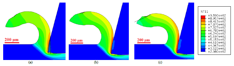
Fig. 3. Temperature contours (in K) of the numerical chip by JC model
(a) 30 m/min; (b) 50 m/min; (c) 75 m/min
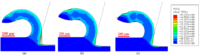
Fig. 4. Equivalent plastic strain contours of the numerical chip by JC model
(a) 30 m/min; (b) 50 m/min; (c) 75 m/min
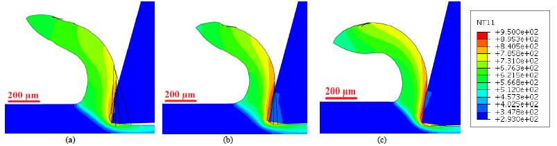 Fig. 5. Temperature contours (in K) of the numerical chip by JC-Hou model
(a) 30 m/min; (b) 50 m/min; (c) 75 m/min
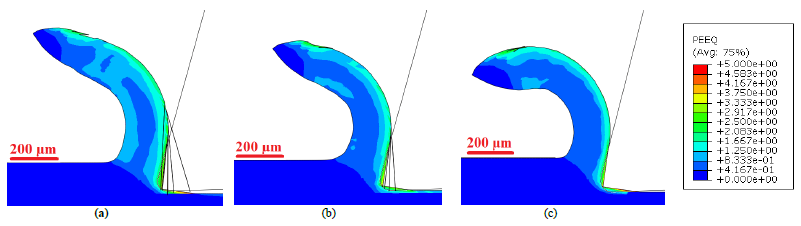 Fig. 6. Equivalent plastic strain of the numerical chip by JC-Hou model
(a) 30 m/min; (b) 50 m/min; (c) 75 m/min
The numerical chips of JC-Calamaz_30, JC-Calamaz_50, JC-Calamaz_75 is compared in Fig.7, The chips are slightly serrated. Indeed, the temperature differences are seen where the temperature is maximum in the secondary deformation zone for all three cutting forces in the same order of JC and JC-Hou models that is JC-Calamaz _75 > JC-Calamaz _50 > JC-Calamaz _30. In addition, highly distorted and more elongated elements are observed in the chip as well as on the surface of the workpiece. The simulated cutting forces from JC-Calamaz models increases with increase in cutting speed (In the order of JC-Calamaz_75 > JC-Calamaz_50 > JC-Calamaz_75). The RMS value of feed force increases with the increase in cutting speed from 57 N/mm for JC-Calamaz_30 to 65 N/mm for JC-Calamaz_75 which is contrary to the JC and JC-Hou models. Indeed, the force ranges are highly distinct from experimental reference.
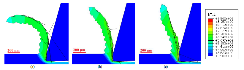 Fig. 7 Temperature contours (in K) of the numerical chip by JCCalamaz model
(a) 30 m/min; (b) 50 m/min; (c) 75 m/min
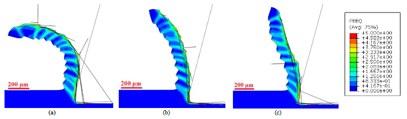 Fig. 8 Equivalent plastic strain contours of the numerical chip by JC-Calamaz model
(a) 30 m/min; (b) 50 m/min; (c) 75 m/min
Fig 4, 6, 8 show the evolution of the chip with respect to equivalent plastic strain contours. The equivalent plastic strain distribution clearly depicts that JC-Calamaz models produces serrated chip whereas, JC and JC-Hou produces continuous chips. In addition, highly distorted and elongated elements are observed with the JC-Calamaz models.
Table 2. RMS cutting force (Fc), feed force (Ff) and chip thickness (h’) summary and Δx differences with the experimental reference
5 Discussion
From all the numerically simulated chips it was observed that the temperature in the secondary deformation zone increases with increase of cutting speed. It was explained by the phenomenon that when cutting speed increases, friction force increases and the strain rate in deformation zones also increase, these induce an increase in temperature in the deformation zones.
For all cutting speeds considered in this study, the variations of forces measured from the experiments are in the uncertainty range. Thus, the feed force and cutting force has no notable influence when the cutting speed increasing from 30 m/min to 75 m/min. The RMS value of cutting force from all JC and JC-Hou numerical models considered in this study show as decreasing trend with increase in cutting speed, Whereas JC-Calamaz model shows an increasing trend with increase in cutting speed. The difference in the RMS values for JC and JC-Hou for the cutting speeds (30 m/min, 50 m/min, 75 m/min) was in the range of 5% to 10% and for JC-Calamaz was in the range of 1% to 4%. It is noteworthy that difference in their cutting force value trends is due to modification of thermal softening function of the JC model by adding temperature-dependent strain softening phenomenon, as an effect strain hardening predominates over the effect of thermal softening [8]. The stress strain evolution curve from Fig 1. clearly shows the influence of the strain softening on the stress level. Hence different stresses level leads to different cutting forces. In addition, it was observed that the feed force from JC-Calamaz also shows an increasing trend with cutting speed increment, but still, they are in the uncertainty range nevertheless, those values are far behind the experimental ones. It is also important to note that the difference between the numerically calculated force values and the experimentally measured force values may be due to the choice of the parameters of the constitutive models. Indeed, they are adopted from the references given in Table 1 and were not identified from the material samples employed for the experimental work.
The comparison of nine simulations with the experimental reference shows that the JC and JC-Hou models gave continuous chip, while JC-Calamaz models gave slightly serrated chip. From the flow stress equations, the JC and JC-Hou law produces continuous chip with uniform strain field, where JC-Calamaz law show a sequence of two unequal segments with high strain localised area and areas where the deformation is very low. However for qualitative comparision, a mean thickness value is calculated by taking the mean of peak and valley values of the JC-Calamaz chips. From the experiments, it was observed that the chip thickness decreases with increase in cutting speed. The chip thickness from numerical chips of JC and JC-HOU, JC-Calamaz also shows a decreasing trend with increase in cutting speed. When looking at the flow stress equations and the stress strain curves from Fig.1, temperature is a decreasing function of flow stress. Thus, when cutting speed increases, the temperatures increase which favors plastic deformation. This could increase side flow which leads to a reduction in chip thickness [9].
6 Conclusion
In this study, influences of cutting speed ranging from 30 m/min to 75 m/min with material constitutive models such as JC and modified JC constitutive material (JC-Hou, JC-Calamaz) on chip formation by numerical simulation are investigated and compared with the experiments conducted for uncut chip thickness of 60 μm. The results from the nine numerical simulations have been verified by comparing the RMS values of the cutting force, feed force, chip morphology, chip thickness with the experimental results.
-
The temperature in the secondary deformation zone increases when changing the flow stress model, and the temperature increment is in the order of JC-Hou > JC > JC-Calamaz. In addition to the temperature increases with increase of cutting speed from 30 m/min to 75 m/min.
-
From the experiments, cutting speed has no significant effect on forces measurements.
-
The simulated forces from JC-Calamaz models are lower than JC and JC-Hou models. This is explained by the lower magnitude of the flow stress, while the parameters of the constitutive models are for the same material.
-
The JC-Calamaz model produce serrated chip contrary to the experimental chip morphology for the cutting conditions considered in this study.
-
Overall, the JC-Calamaz model is not well suited for this particular cutting condition.
Acknowledgements
Computational resources have been provided by the Consortium des Équipements de Calcul Intensif (CÉCI), funded by the Fonds de la Recherche Scientifique de Belgique (F.R.S.-FNRS) under Grant No. 2.5020.11.
