1. Introduction
Constitutive models are one of the key aspects when modelling a cutting operation [1]. They indeed directly influence the accuracy of the results: magnitude and temporal evolution of cutting forces, chip morphology and geometry, etc., justifying significant research activities in this field [2]. The severe conditions induced by the cutting process on the workpiece material makes it difficult to identify its behaviour. Empirical constitutive models are currently widely adopted. The Johnson-Cook (JC) model [3] is the most used of them, even if it is known to have some limitations [2]. To overcome them and try to come closer to the actual material behaviour, many models have been introduced the last decade [4]. This usually has the consequence of increasing the number of parameters to identify. This identification is also a hard task that requires dedicated equipment to reach the high levels of strains, strain rates and temperatures of the cutting process [2]. The most used in this context are the Split Hopkinson Pressure Bars [5] and the Taylor impact test [6]. This later consists in launching a cylindrical specimen at a prescribed speed to impact a rigid anvil. An identification method consists in modelling the test to determine the constitutive model parameters by comparing the experimental and the numerical samples geometries after deformation (i.e. “inverse identification” procedure). Numerical modelling of the test is usually performed with the finite element method and the Lagrangian formulation [7]. However, elements deformation and/or distortion typically generated during the computation decreases the accuracy of the results and may significantly impact the values of the parameters. To overcome this limitation, this paper adopts the Coupled Eulerian-Lagrangian (CEL) formalism, already used for modelling high strain, strain rate and temperature problems such as a cutting operation [8,9], instead of the Lagrangian one for the development of a 3D model. The suitability of the formalism is first assessed with the JC model against a Lagrangian reference, before applying it to an improved version of the JC constitutive model.
2. Finite element models
Two 3D finite element models are developed with Abaqus/Explicit in the frame of this article: a Lagrangian model, acting as a reference, and the introduced CEL model. They both include a quarter of the actual configuration (Figure 1), with the corresponding symmetry boundary conditions, to reduce the computation time. The cylindrical sample has a length of 32.4 mm and a radius of 3.2 mm. Its prescribed initial speed is 200 m/s and its initial temperature is 20°C. A perfect contact between the specimen and the rigid plate is assumed without friction. The simulation time is 80 μs. This configuration is the same as Ming and Pantalé’s [10].
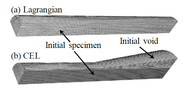
Figure 1. Initial geometry of (a) Lagrangian model and (b) CEL model with their fine mesh
Special care must be taken for the CEL model due to the coupling between the Eulerian and Lagrangian formalisms. The mesh (Figure 1 (b)) needs to include the volume in which the material will be during the simulation. This implies that the dimensions of the mesh are larger for the CEL model than for the Lagrangian model; in the Lagrangian model, only the specimen needs to be meshed. Consequently, the mesh of the CEL model is made of a cylinder and a cone. The cylinder is slightly larger than the undeformed part of the specimen and the cone is slightly larger than the final deformed part of the specimen. This geometry allows reducing the size of the mesh and consequently the computation time. Figure 1 (b) shows both the initial specimen geometry in light grey and the initial void, where the specimen can deform during the simulation, in white.
The material of the specimen is the 42CrMo4-FP ferritic-pearlitic steel with an inelastic heat fraction coefficient of 0.9. Its behaviour is first described by the JC constitutive model:

It requires the identification of five parameters 𝐴, 𝐵, 𝑛, 𝐶 and 𝑚. 𝜀̇0 is the reference strain rate. 𝑇room is the room or reference temperature and 𝑇melt is the melting temperature. The JC constitutive model is introduced in Lagrangian and CEL finite element models with the VUMAT subroutine developed by Ming and Pantalé [10]. Material properties and JC parameters of 42CrMo4-FP steel are included in Table 1.
Table 1. Johnson-Cook parameters and material properties of 42CrMo4-FP steel [10]
![Table 1. Johnson-Cook parameters and material properties of 42CrMo4-FP steel [10]](docannexe/image/316/img-3.png)
3. Validation of the CEL model
The introduced CEL model is first validated against the Lagrangian model acting as a reference. A perfect match of the results is not expected, but they should be close enough to assess the suitability of the CEL formulation. A mesh sensitivity study is first conducted to determine the mesh configuration that should be adopted to model the 3D Taylor impact test. Four mesh densities are used: coarse (elements size of 0.8 mm), medium (elements size of 0.4 mm), fine (elements size of 0.2 mm) and very fine (elements size of 0.15 mm). In the Lagrangian model, C3D8RT elements are used, i.e. 3D linear 8-node with reduced integration and temperature degree of freedom elements. In the CEL model, Eulerian 3D linear 8-node with reduced integration and temperature degree of freedom elements, EC3D8RT, are used. Computations (coupled temperature displacement analyses) were run on Abaqus/Explicit v.6.14-2 and Windows 10 64 bits with 8 GB of Ram. Four cores of an Intel i7-5700 HQ 3.48 GHz processor were used for the computation of each simulation with double precision. FORTRAN VUMAT subroutines were compiled with Intel Fortran Compiler 16.0.4.
Figure 2 and Figure 3 show the results of the eight models to allow comparison of the two formulations and carry out the mesh sensitivity study. As expected, high plastic strains are located at the bottom of the specimen, in the region of impact, and the highest values are in the centre. The tendency of these results is in accordance with the experimental results of a symmetric Taylor impact test for the same material but different impact speed and sample dimensions [7]. From Figure 2, it is clear that the mesh density influences the Lagrangian results: the deformed radius on the impact face increases with the mesh density. This influence is more difficult to notice on the CEL results in Figure 3. The influence of the mesh on the equivalent plastic strain values is also lower for the CEL formulation than for the Lagrangian formulation for which a strong (and unrealistic) localisation is observed. This means that the more the Lagrangian mesh is refined, the more the equivalent plastic strain increases due to distortion of the mesh with no convergence of the results. On the contrary, the equivalent plastic strain values converge when the CEL mesh is refined. Localisation of the deformation and mesh dependence of equivalent plastic strain for the Lagrangian formalism together with a comparison for the CEL formalism are shown in detail in Figure 4. Some kind of defects (looking like small indentations) are observed on the results of coarse and medium CEL meshes in the undeformed region of the specimen. They are linked to the thickness of the initial void region that is too small by comparison to the elements size; they are not spotted anymore for fine and very fine meshes. Due to the interpolation used by Abaqus to determine the contours of the area filled with material, the upper corner of the specimen is rounded. The value of the radius is directly linked to the size of the elements, explaining why it decreases when mesh density increases. Both types of artificial defects are far from the relevant region and have no influence on the results; they will be ignored in the results analysis.
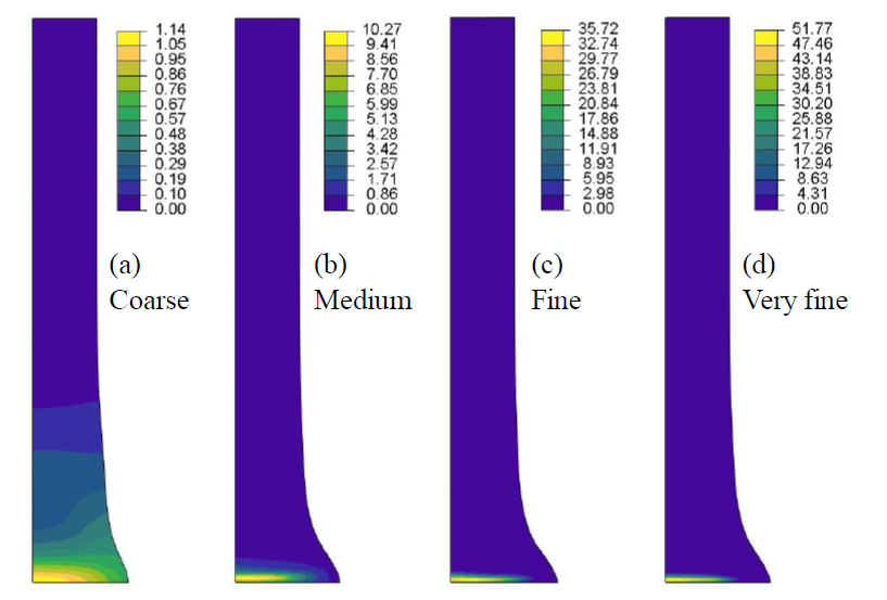
Figure 2. Equivalent plastic strain results for the 4 Lagrangian models
(a) coarse mesh, (b) medium mesh, (c) fine mesh and (d) very fine mesh
Table 2 gives the results of both models for the four different mesh sizes:
-
𝐿f and 𝑅f are the final length and radius of the specimen, respectively. Measurements of the specimen deformed geometry are performed in a lateral face of the specimen.
-
𝜀̅max is the maximal equivalent plastic strain, 𝜎max is the maximal equivalent von Mises stress and 𝑇max is the maximal temperature.
-
𝑁elements is the number of elements of the model, 𝑁increments is the number of increments to complete the computation and 𝑡̂CPU is the normalised (by the Lagrangian model with a fine mesh) computation time of the model.
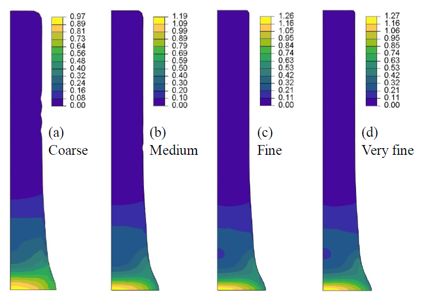
Figure 3. Equivalent plastic strain results for the 4 CEL models
(a) coarse mesh, (b) medium mesh, (c) fine mesh and (d) very fine mesh
They allow to validate the CEL model by comparison with the Lagrangian results: all the results are close, even if some differences can be noted. Regarding the mesh sensitivity study, for both models, the fine mesh should be used as it provides a good accuracy in terms of specimen geometry at the lowest computation cost. It must however be noted that, while the final lengths are very close, the final radius is larger for the Lagragian model. This is explained by the large deformation of the elements at the end of the specimen (in the impact region), decreasing the accuracy of the results. The absence of elements deformations in the CEL formulation avoids this problem and therefore provides more accurate and reliable results.
When looking at the mesh influence on the maximal equivalent plastic strain, 𝜀̅max, the maximal equivalent von Mises stress, 𝜎max, and the maximal temperature, 𝑇max, values, convergence seems to be achieved for all but the equivalent plastic strain of the Lagrangian model. Since plastic strains are not converging, convergence of stresses and temperatures of the Lagrangian model were not expected. Convergence of stresses is linked to the shape of the flow stress, rather flat for the material conditions in that area. This implies that a large variation in plastic strain results in a small variation in stress (and so an apparent convergence). Since temperatures are computed from plastic strains and stresses, compression of element has a counterbalancing effect that can explain stabilisation of temperature values.
Regarding the CPU computation time, although the number of increments, 𝑁increments, is close for both models, the larger number of elements, 𝑁elements, and the increase in the CPU cost of one increment lead to a significant increase for the CEL model. As expected due to elements deformation with the Lagrangian formulation, time increment value decreases during computation for the Lagrangian model (from 15.8∙10-9 s at the beginning of the computation to 5.4∙10-9 s at the end of the computation for fine mesh), while it is constant in CEL (7.6∙10-9 s for fine mesh). To set the magnitude of the computation time, 221 s are needed for the Lagrangian model with the fine mesh.
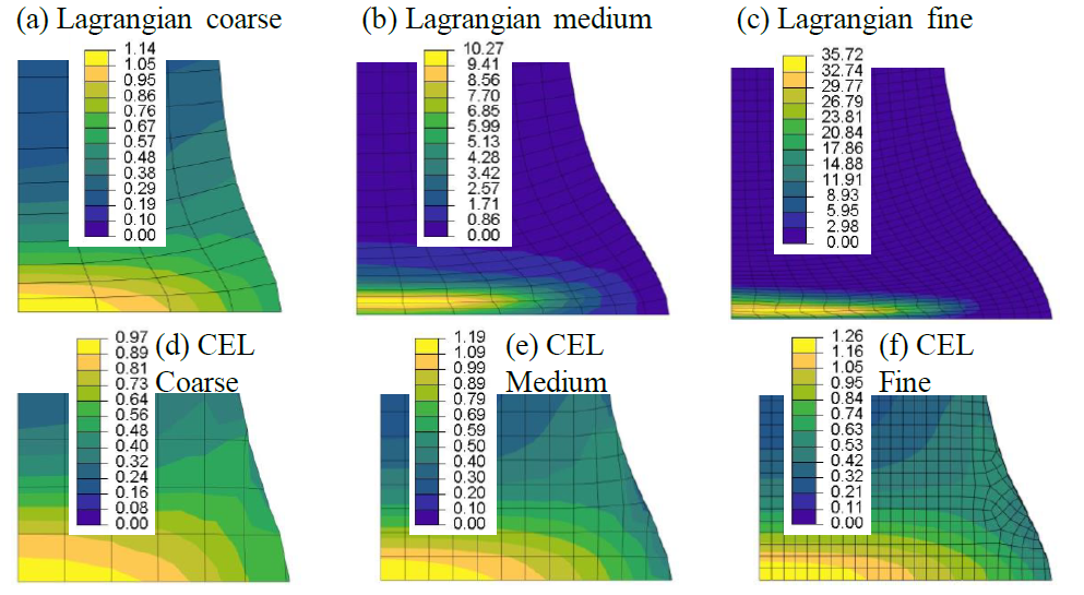
Figure 4. Detail of the mesh at the deformed end of the sample, equivalent plastic strain:
Lagrangian (a) coarse mesh, (b) medium mesh, (c) fine mesh and CEL (d) coarse mesh, (e) medium mesh, (f) fine mesh
Table 2. Results with JC constitutive model (converged mesh in bold)
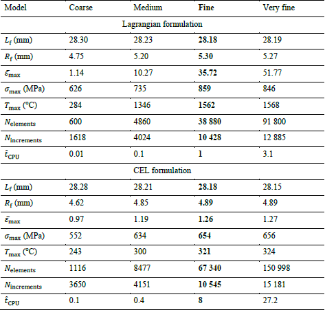
As a conclusion, the large deformation of elements in the Lagrangian model results in extremely high (and unrealistic) values of equivalent plastic strain and a larger radius of the deformed specimen by comparison to the CEL model. The better performance of this model has however a higher CPU cost due to the larger mesh domain, resulting of the inclusion of the volume where the material can deform during the simulation.
4. Application to an alternative material constitutive model
Both models with their converged mesh (i.e. fine mesh) are now extended to the use of an improved Johnson-Cook model: the Hyperbolic TANgent (TANH) model, one of the most used models based on JC. TANH model has been introduced by Calamaz et al. [11] to take the strain softening of the material into account:
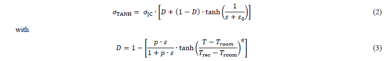
where 𝜎JC is computed with equation (1), 𝑝 and 𝑞 are additional parameters, 𝜀0 sets the strain corresponding to the peak stress and 𝑇rec is the onset temperature for strain softening. Parameters of TANH model for 42CrMo4-FP ferritic-pearlitic steel are provided in Table 3. This constitutive model has also been implemented in the models via a VUMAT subroutine developed by Ming and Pantalé [10].
Table 3. TANH parameters of 42CrMo4-FP steel [12]
![Table 3. TANH parameters of 42CrMo4-FP steel [12]](docannexe/image/316/img-9.png)
Comparison of the results between JC and TANH material constitutive models (Figure 5 and Table 4), for both formulations, leads to values that are very close to each other. It can also be highlighted that results for JC and TANH are even closer for the CEL formulation, which is in accordance with the convergence of all the indicators for this formulation. The conditions of strain, strain rate and temperature in which the material is, do not trigger the modifications introduced by the TANH model. This is in accordance with previous results obtained by Ming and Pantalé [10] and confirms that the CEL model can be used for 3D modelling of the Taylor impact test.
Table 4. Results with JC and TANH constitutive models for Lagrangian and CEL formulations with a fine mesh (JC results are the same as in Table 3, they are included here for an easier comparison)
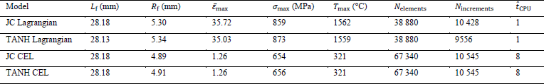
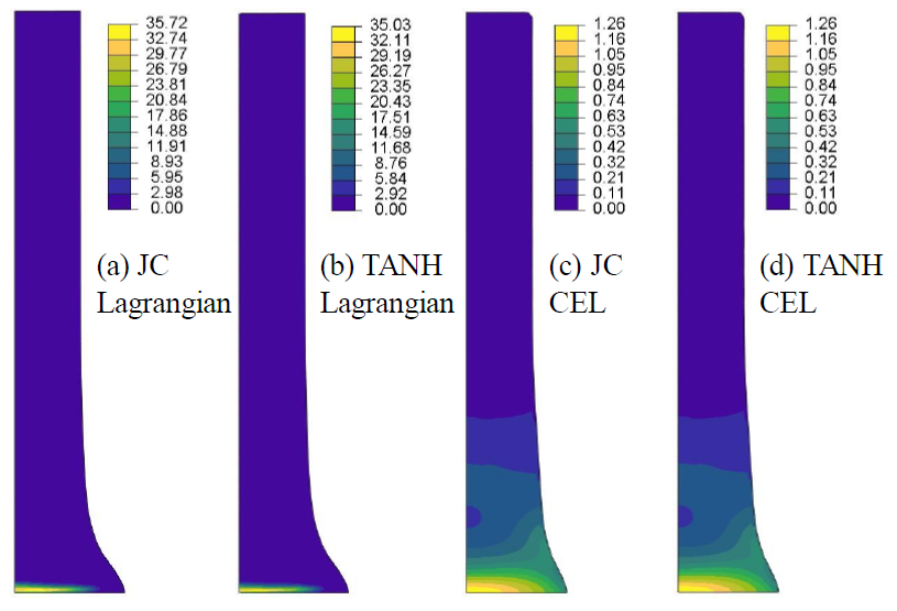 Figure 5. Equivalent plastic strain results with fine mesh for:
(a) Lagrangian with JC, (b) Lagrangian with TANH, (c) CEL with JC and (d) CEL with TANH
5. Conclusions
The CEL formulation has been introduced in this paper to model the 3D Taylor impact test with Abaqus/Explicit. Both Johnson- Cook and Hyperbolic TANgent material constitutive models have been adopted via VUMAT subroutines. Results showed that the CEL model delivers results close to the Lagrangian reference. Performances of the CEL formulation are better when high strains are generated thanks to the absence of elements deformation. Indeed, no plastic strain localisation, nor increase of specimen radius with mesh density were generated. In addition, the mesh convergence study showed that both geometrical and material related indicators were converging in the CEL model, contrary to the Lagrangian model. Replacing the Johnson-Cook constitutive model by the TANH model confirmed these observations. All these results show that the CEL formulation should be considered in the future as a reliable and accurate alternative to the Lagrangian formulation for inverse identification of the parameters of material constitutive models parameters from dynamic impact tests such as the Taylor impact test.
