1 Introduction
Nowadays the reduction of air pollution and harmful climate emissions is adjusted by law and a highly addressed topic in the public and private sector. Especially the automotive industry as a big part of the mobility sector is addressed to lower the CO2 emission of future vehicles. Lightweight materials like high strength steels and fiber reinforced plastics offer a promising approach for these targeted high performance components. The hybrid material combination e.g. fiber reinforced plastic (FRP) - metal laminates leads to consequent weight reduction while the functional integration by the form flexible plastic component improves. An economical obstacle to use the hybrid material is its integration into existing manufacturing processes.
For part manufacturing, different kinds of processing steps are used: forming, trimming, joining and several more. The knowledge about suitable cutting methods is crucial for the application of the hybrid materials because of its many occurrences along the manufacturing process. In process development, the cutting procedure is evaluated in the conflict area of the target values process time, cutting edge quality and accuracy. In addition, the integration of the cutting step into existing process routes is decisively for the cutting method. Commonly the application of drilling [1,2] and waterjet cutting [3–5] are used for FRP-metal materials. Due to the low compatibility to the complex manufacturing process steps of the automotive industry other cutting processes need to be identified. A promising alternative is the stamping process which is already used in the bodywork [6 7]. Those processes are highly productive due to the process times and thus are cost efficient compared to other technologies. Disadvantages are the tool related geometry, the appearance of wear at the tool and applied cutting forces on the working material itself [8,9].
The shear cutting technique is an established method to produce final contours in sheet metal forming. The process is realized by moving a punch against the die. The geometry of the cutting edge of steel sheet materials is defined in VDI 2906 [10] and shown in Fig. 1 (a).
The relevant parameters for the shear cutting process can be divided into three different groups: tool, working material and process-related parameters. The tool parameters include the tool geometry of the punch, the tool materials and friction reducing coatings. The geometrical parameters of the tool are shown in Fig. 1 (c). The main influence on the cutting force is performed by the die clearance u. A larger clearance leads to lower cutting forces and therefore lower wear at the tool cutting edge but also induces a high deformation of the sheet material due to the applied bending forces (see Fig. 1 (b)). When developing a shear significantly is the applied blank holder force FNH (see Fig. 1 (b)).
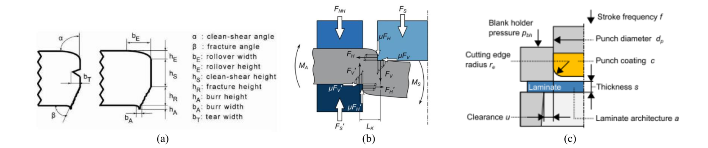
Fig. 1. (a) Cutting edge quality criteria [12] (b) forces in shear cutting process [9] (c) tool and workpiece parameters in shear cutting process [13].
Since there has not yet been extensive research in cutting the hybrid material of FRP-metal-laminates it is evident to have a look at the shear cutting of the single components. As mentioned before, sheet metal materials are commonly cut by shear cutting and therefore the process and its parameters is well known. When using this knowledge for FRP, it is essential to understand the FRP structure. FRP shows inhomogeneous failure behavior due to the ductile matrix and stiff, brittle fibers. In addition, anisotropic mechanical behavior of the FRP is caused by the fiber reinforcement. When shear cutting FRP, the angle of the fibers in the cutting area has a significant influence on the resulting cutting force [8]. The cutting forces of steel sheets are usually higher and more constant than the forces when cutting FRP. However, the difference of the cutting force value between the material combinations in hybrid components are expected to be related to the FRP-type (weaving type, fiber material) used.
In [14], the shear cutting process (punching) for hybrid materials is investigated. The results show the relation of the cutting direction (FRP or steel component at the top side) and the cutting edge geometry. When the steel component is faced up (see Fig. 2 (b)), the accuracy of the cut at both materials is higher. The roll over width tends to increase compared to the other cutting sequence when the FRP is faced up. Also a trend of increased fiber pull-out is detected for the cutting sequence Steel-FRP. When cutting FRP-steel, we observe that the FRP always overlaps the steel component and as consequence of fiber breakage and delamination the laminate thickness increases (see Fig. 2 (a)).
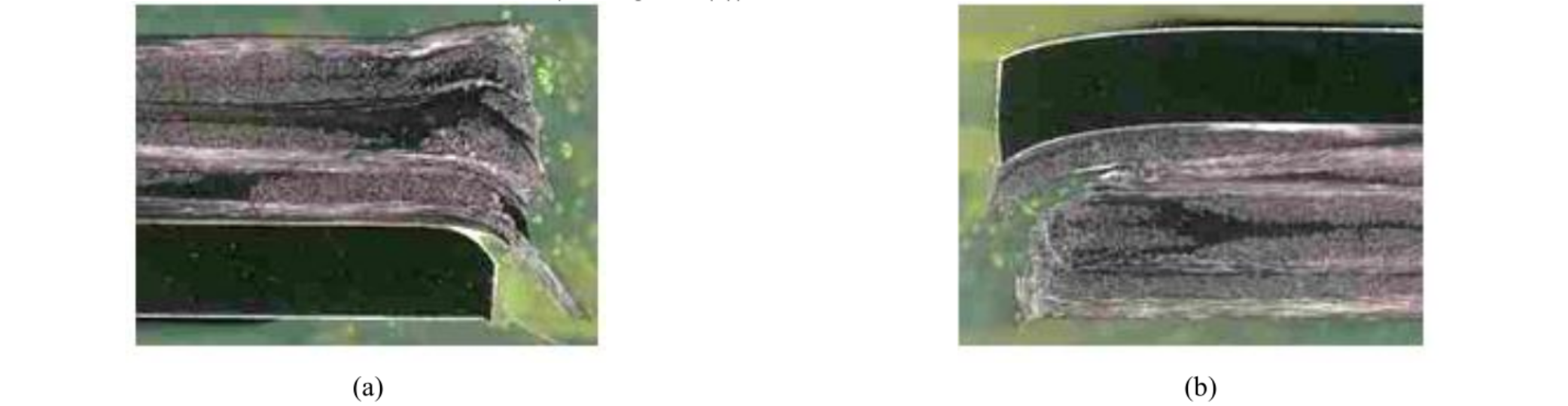
Fig. 2. Micro section of hybrid steel-FRP material, separated by shear cutting method.
The cutting edge quality shown in the studies do not meet the quality requirements of series production. Hence, a better understanding of the mechanisms when cutting hybrid materials is needed. In this contribution, the objective is to investigate different material combinations in terms of steel, FRP and the bonding agent in between, the cutting sequence and specimen geometry.
2 Method and Experimental Setup
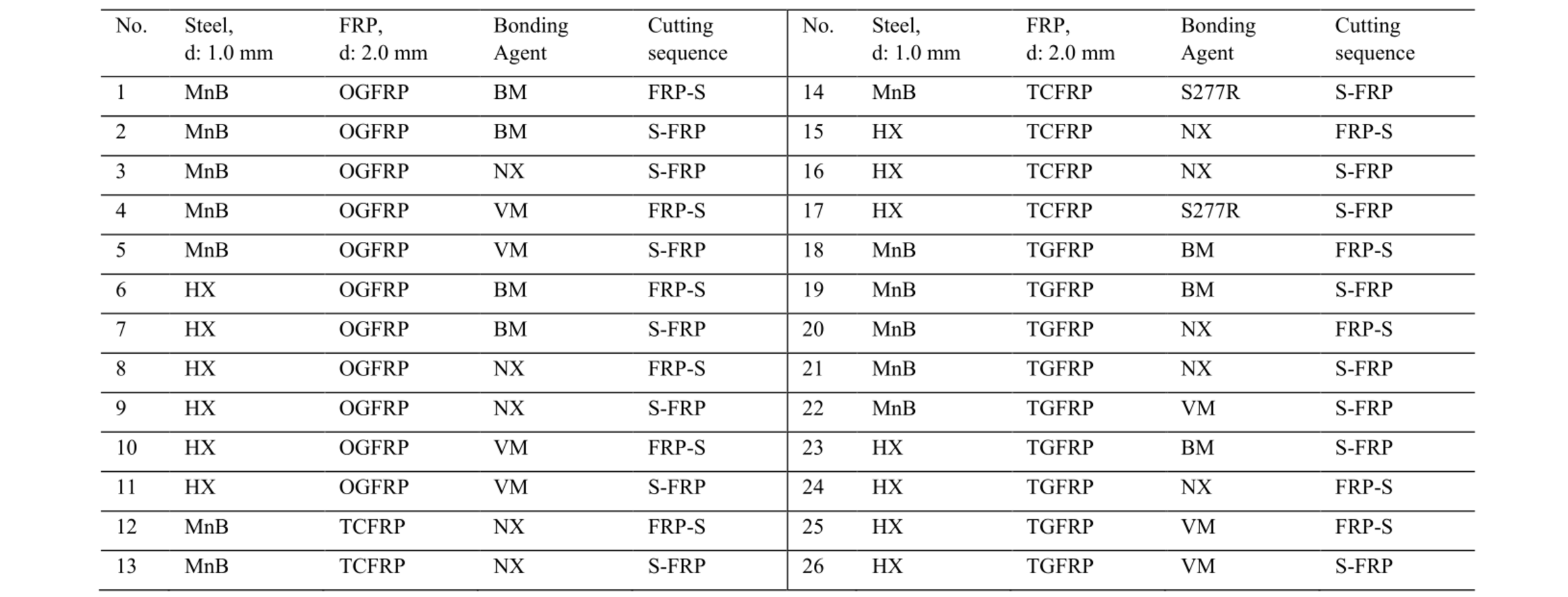
In this study, the piercing method is used. In order to analyze only the influence of the used material combination, the constant process parameters given in Table 1 were used. Only the cutting sequence is varied. The punches and dies were made of steel 1.2379 hardened to 60 HRC. A small die clearance is used to ensure a clean cut of the fibers in the FRP material. Consequently, high cutting forces occur and only little deformation of FRP and steel are possible. The specimen geometries and corresponding dimensions are shown in Fig. 3. Both cutting edges were observed but only the blanked parts were used for the micro sections.
Table 1. Parameter selection and values.
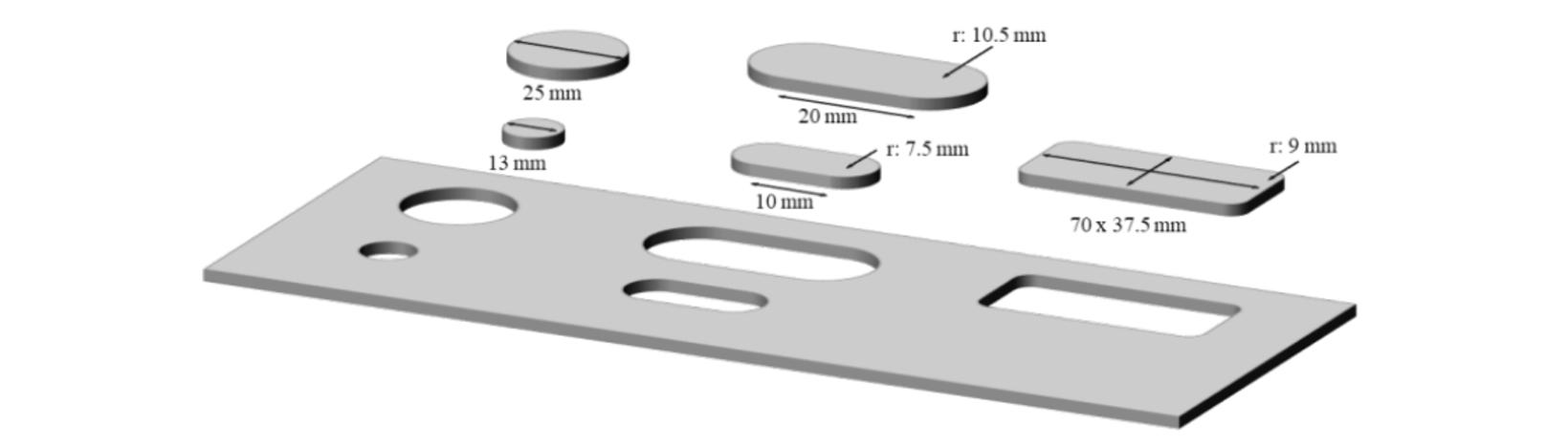
Fig. 3. Investigated specimen geometries and dimensions.
For sheets consisting of FRP material and steel, it is necessary to use a bonding agent for adhesive bonding. The method used to apply the FRP on the steel is a heated pressing process. Pre-cut semi-finished products (350 mm x 350 mm) are stacked and heated up to FRP melting temperature of T = 220 °C in t=360 s in a ventilation oven. By applying a pressure of p = 100 N/cm2 the stacked FRP-steel laminates are joined in a heated press machine. After cooling for t=120 s, the plates are taken out of the machine.
Table 2. Materials selection.
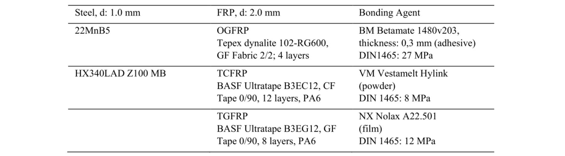
To investigate a wide performance range of materials three different kinds of steel, FRP and bonding agents were used in this research (see Table 2). All materials were chosen as there are already used or identified to fit in the applications of the automotive industry especially in car body. For the steel component a cold-forming (HX) and hot-forming (22MnB5) material where selected. All the FRP components consist of polyamide 6 (PA6) matrix which is a high performance thermoplastic. The fibers used are glass fiber (GF) and carbon fiber (CF). GF is used in fabric twill 2/2 (OGFRP) and unidirectional tape in 0/90 ° fiber direction (TGFRP). CF only appeared as stacked unidirectional tape (TCFRP). The bonding agents are selected due to their different mechanical performance. in order to analyze the bonding strength needed to prevent delamination between steel and FRP. Table 3 shows the laminate variations used for the investigations.
Table 3. Materials selection and investigated laminate architectures.
To quantify the accuracy of the cut, the punched specimens were measured by caliper (five times each dimension in width and length). The average value is used to compare the results. Since a large surface area offers higher potential for corrosion due to the large contact area, the surface roughness parameters Ra (arithmetic mean roughness value) and Rz (mean roughness depth) were detected on the steel clean shear surface at the elongated specimen (20 x 10.5) with a MarSurfUD130 machine. While measuring the FRP roughness it turned out that the deviations between the values were too high to offer sufficient comparability. Therefore, roughness values could only be collected at the steel component.
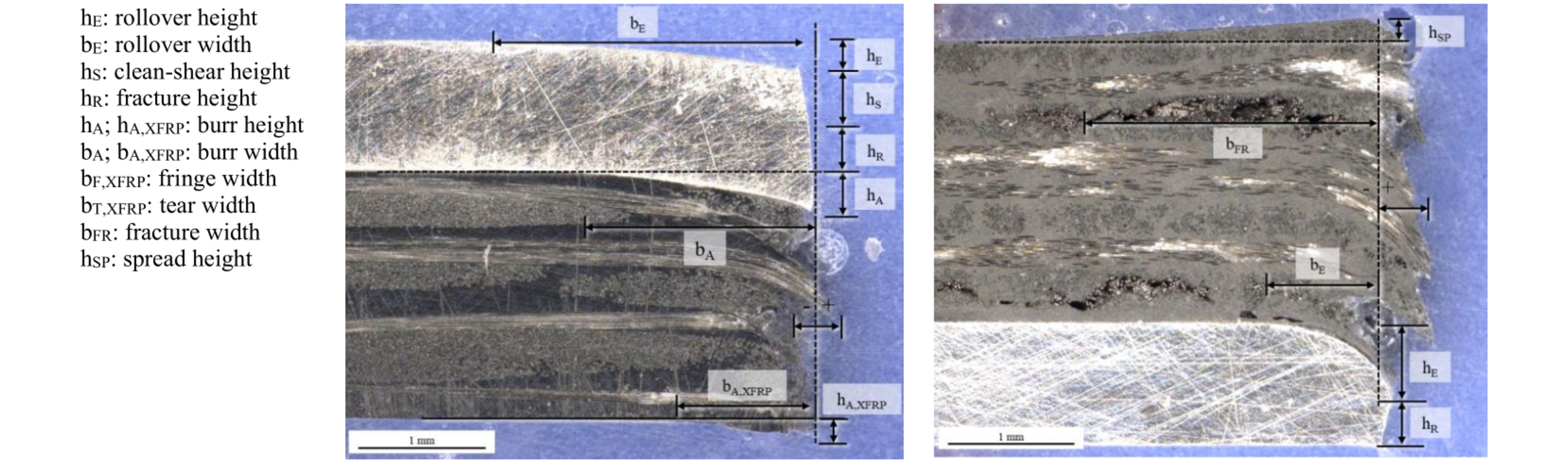
Fig. 4. Cutting edge surface parameters in hybrid steel-FRP components.
In addition, micro sections were created to qualitatively analyze the cutting edge geometry (see Fig. 4). Thereby, the cutting edge criteria of VDI 2906 were taken into account and extended for FRP material. The emergence of delamination and fiber fracture is determined by means of measurement with Keyence VHX700F in the micro section. It has to be kept in mind that micro sections are just able to show a snapshot of one section which limits the representation for the complex FRP component. To prepare the specimen a cut-off machine was used. A possible influence of this technique on the cutting edge geometry and fiber position cannot be excluded. By using water cooling and low feed rates this influence was reduced to a minimum.
3 Results and Discussion
3.1 Materials
In the experiments, different types of steel, FRP and bonding agents are used. There results were analyzed by micro sections. The analysis of the cutting edge showed high fiber breakage in the FRP part. In general, all possible types of damage occur, such as fiber pull-out, fiber breaks, and fringe and interlaminate damage.
The two steel types differ in the material related specific cutting force k S, which leads to different forces in the cutting edge. These forces are applied onto the FRP component when the critical strain of the steel is exceeded. This could lead to other damaging behavior in the FRP but there were no correlations between the FRP failure and steel type detected.
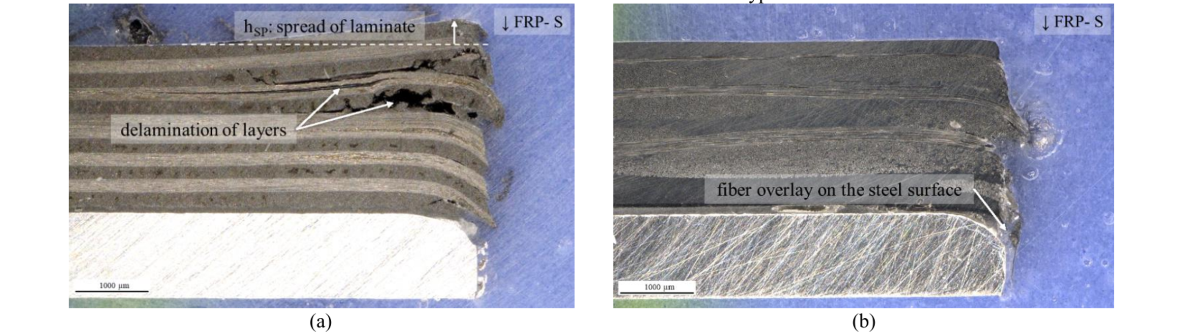
Fig. 5. Micro sections of (a) structural damage of TCRFP specimen and (b) cutting edge of an OGFRP specimen.
In Fig. 5, the micro section of TCFRP and OGFRP specimen is shown. The TCFRP specimen showed structural damage as displayed in Fig. 5 (a). It is assumed that this failure is a result of the tools motion. The reverse movement of the punching tool lifts the stiff CFRP layers wedged on the tool, which leads to delamination and an increase in thickness. For GFRP, this delamination effect was investigated only partially for GFRP, which correlates with the less brittle behavior of GF in comparison to CF. Thus, the relatively large stiffness and high strength of the carbon fibers leads to wedging onto the tool and consequently to delamination and fiber breakage. In Fig. 5 (b), the OGFRP micro section shows fiber fringes and the overlay of the fringes on the steel component. When comparing Fig. 5 (a) and (b) the TCFRP specimen showed a more accurate fiber orientation in the cutting edge than the OGFRP specimen due to its lower fracture elongation.
Furthermore, the variation of the bonding type targeted the sensibility of the compound concerning shear load in the interface. The specimens with VM showed a high amount of total delamination of the blanked geometries. This is a result of the low bonding strength of the material. In addition, the thickness of the VM bonding layer is the lowest, which leads to less stress load capacity. The NX system showed high deformation ability in the cutting edge area where steel and FRP are bend. The specimens with the adhesive bond (BM) showed different deformation behavior due the significant increase of thickness compared to the other bonding agents (NX, VM).
3.2 Cutting Sequence
The variated cutting sequences showed specific deformation behavior. When using the cutting sequence S-FRP some specimen showed high amount of fiber fringes resulting in an overlay at the steel component, as pictured in Fig. 6 (a). This is caused by the reverse motion of the punching tool. This effect was only investigated for GFRP specimens. For S-FRP were also more orthogonal cutting edges investigated. This is related to the rheological performance of the FRP. For S-FRP, the steel component transfers the forces of the punch directly into the FRP component, which is cut by the edges of steel component and die. In the opposite direction, the punch force is transferred by FRP onto the steel component. Due to its inhomogeneous structure fringes appear and the accuracy in the steel component decreases since the punch is not directly pressing onto the steel.
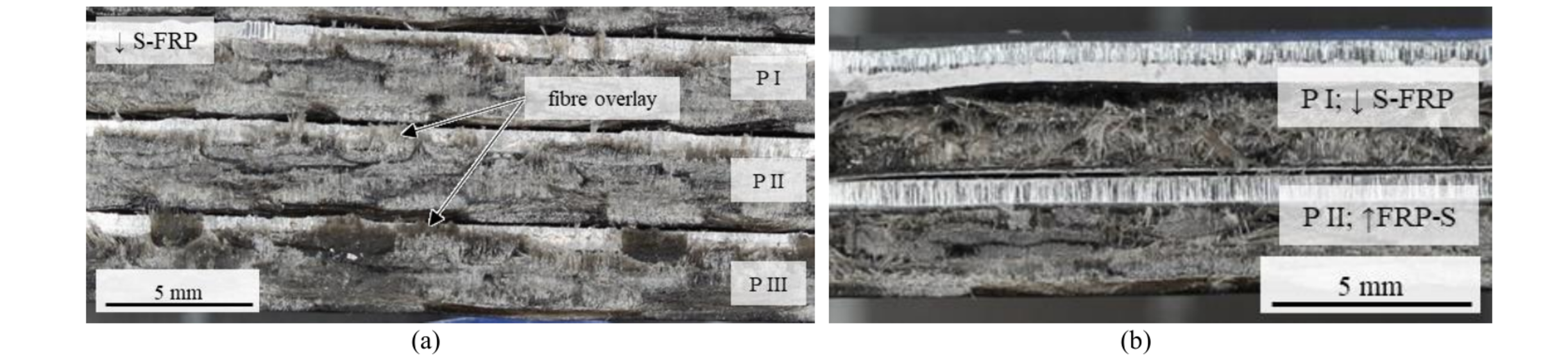
Fig. 6. (a) Fiber fringes on the steel surface of specimen as a result of tool reverse motion (No.3: 22MnB5 – NX – OGFRP) (b) structure of cutting edge on the front view for different cutting sequences.
In Fig. 6 (b), the front view of the two investigated cutting sequences is shown. For S-FRP an uneven and weaved structure of the cutting edge appears. As explained before in this cut the FRP is cut as a result of the steel component which transfers the forces. Due to its less strength the FRP component is deformed and as a cutting base for the steel this leads to high deformation in the steel too. The opposite cutting sequence shows a straight cutting edge of the steel component since the steel is connect to the die. Compared to a classical steel cutting edge the quality of the cut is reduced.
3.3 Surface Roughness
The results of the roughness measurement at the cutting edge for different material combinations depending on the cutting sequence are shown in Fig. 7. Here, only OGFRP-steel laminates are shown exemplary. In Fig. 7 (a), the results for 22MnB5 as steel component are depicted. No data were collected for the combination OGFRP–NX. The results for HX steel can be found in Fig. 7 (b).
When comparing the results, the values for 22MnB5 are slightly higher than for HX steel. Due to the martensitic structure and therefore brittle behavior of 22MnB5 this can be explained by a larger fracture height (hR) to clean cut (hS) ratio. In addition, a trend for the influence of bonding component can be detected in the average values. The usage of BM and VM lead to higher surface roughness than with NX.
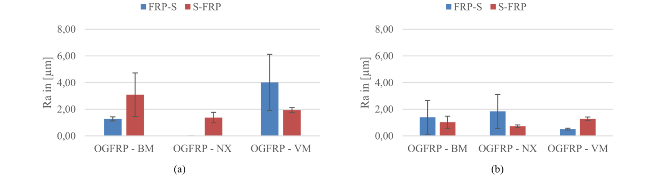
Fig. 7. Surface roughness value Ra for (a) 22MnB5 (b) HX for different material combinations and cutting sequences.
The influence of the cutting sequence is not significantly detectable in the roughness values. The deviation in the five measurements is too high, especially for the cutting sequence of FRP-S. This can be seen on the cutting edge shown in Fig. 8. When cutting from the steel surface the typical and even cutting edge surface occur which can be separated into the clean shear and fracture height. For the other cutting sequence these characteristic values are not clearly detectable. The surface is more fractured and therefore more inhomogeneous. The results show this dependency partly but not reliable.
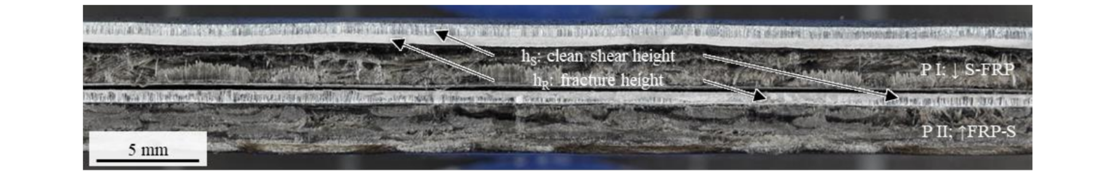
Fig. 8. Cutting edge surface characteristics for different cutting sequences (HX-OGFRP-VM).
3.4 Dimensional Accuracy
Based on the geometries shown in Fig. 3, the dimensional accuracy was determined by measuring the resulting specimen size. As an absolute deviation from the target value, the results for the FRP and the steel component are shown in Fig. 9 as box plot. The box width itself represents the space where 50 % of the values are inside.
Overall the FRP values are higher and more spread than the steel values. Therefore, the accuracy of the steel material is higher (box width: 0.1 mm) than the values for FRP (box width: 0.2 mm). In addition, the deviation from the targeted value is lower for the steel component (0 to 0.1 mm) compared to FRP (0.1 to 0.4 mm). Especially the matrix of the FRP component behaves more ductile and elastic what leads to more deformation tolerance. Due to the fact that the values can be influenced by the choice of the right punch and die sizes as well as die clearance, this is no obstacle for the application of shear cutting.
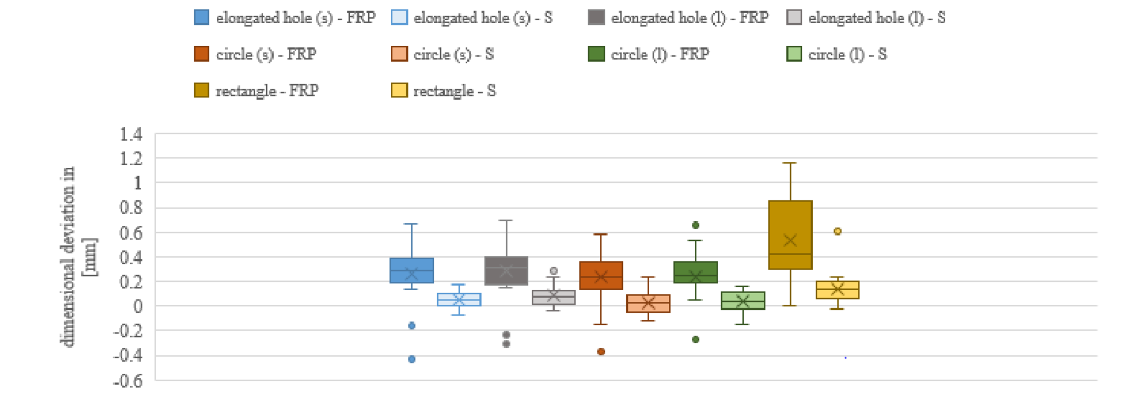
Fig. 9. Absolute dimensional deviation of FRP and steel (S) component in different specimen geometries (s: small; l: large).
Some outlier values of the FRP values are positioned in the negative deviation. These values occurred at laminates with TCFRP material. The highest FRP values were detected for specimen with TGFRP. It is summarized that for cutting TCFRP it is expedient to use larger punch dimensions while realizing the cut at TGFRP materials a smaller punch dimension is useful. The TCFRP values tend to show smaller resulting geometry while the TGFRP values showed the opposite. The investigated OGFRP values occurred in between these minima (TCFRP) and maximum (TGFRP) values. The FRP values for the rectangle geometry showed the highest spread and deviation but no outlier values. As it has the biggest size of the geometries investigated this could be an explanation for FRP value deviation.
4 Conclusion
In this contribution, shear cutting of hybrid FRP-steel laminates was investigated experimentally analyzing the influence of cutting sequence and material. As quality criteria, surface roughness, dimensional accuracy and failure detection in micro sections were evaluated.
There was no significant influence of the steel type detected. In contrast to this, the quality is highly related to the type and fiber orientation of the FRP material which leads to different challenges. The CFRP specimens showed higher accuracy of the cutting edge than GFRP based specimen. Additionally, the occurrence of delamination in the CFRP leads to delamination in the zone of the cutting edge which yields unwanted dimensional deviations and mechanical performance reduction. Comparing the fibers, the GFRP specimens show high amount of fiber fringes and overlay on the steel surface, which can influence further processing steps. The specimen with the bonding agent Vestamelt Hylink showed mostly full delamination between steel and FRP. Therefore, the usage of bonding agents with more than 8MPa bonding strength is recommended in the shear cutting process. There was no influence of the type of state of the bonding agent (e.g., powder or film) detected.
Further, the cutting edge geometry is related to the cutting sequence. Depending on the part geometry the accessibility to surfaces can vary and therefore the resulting cutting edge geometry is influenced. Especially the results for the cutting sequence S-FRP showed large roll over dimensions and a waved contour of the cutting edge of the steel component. To reduce this deformation, it is possible to use different shear cutting methods (e.g., fine blanking, counter-shaving, high-speed shear cutting) and punching tool geometries. Also a combination with a higher blank holder force could lead to lower deformations in the cutting edge area. The opposite cutting sequence FRP-S leads to less deformation of the steel component but to higher variations in dimensional accuracy and the surface parameters e.g. roughness. Also it was shown that the steel component offers higher dimensional accuracy while the FRP component always showed higher deviations from the target value. This needs to be considered when shear cutting hybrid steel-FRP components.
In general, the analysis of the quality of the cutting edge is difficult due to missing suitable measurement techniques. Alternative methods could be the fluorescence correlations spectroscopy and the optical coherence tomography. However, shear cutting is a suitable process for cutting hybrid materials while offering a high potential to be integrated in existing manufacturing processes.
Acknowledgement
This research and the results published are based on the research program Mobilise funded by the Ministry of Science and Culture of Lower Saxony and the Volkswagen Foundation. In addition, the collaboration with the partners at the Open Hybrid LabFactory, Wolfsburg, Germany is gratefully acknowledged and appreciated.
