1 Introduction
Fibre reinforced plastics are playing an increasingly important role in the automotive industry. Due to the high specific strength and stiffness of the composite, significant weight savings can be achieved and mechanical component requirements can be met [1]. Especially fibre-reinforced thermoplastics (FRTPs) are particularly suitable for large-scale automotive production, as short cycle times can be achieved. Organo sheets or FRTP-tapes containing of continuous fibre reinforcements are commonly used to produce shell-shaped components like battery trays or seat shells [2,3]. Through an optional subsequent injection moulding process, stiffening or connecting elements can be generated through a substance bond to the organo sheet or FRTP-tape [4].
1.1 Thermoforming process
A typical forming process for such components is thermoforming. The semi-finished product is first heated to a temperature above the melting point of the thermoplastic matrix material. Subsequently, it is draped into the component geometry in a mould (see Fig. 1). Optionally, a blank holder or tension frame can also be used, which stretches the semi-finished product during forming to reduce unfavourable wrinkling. However, excessive blank holder forces can lead to high residual stresses or even fibre breakage [5].
The forming is based on fibre elongation, inter ply shear and intra ply shear. To avoid rapid cooling of the semi-finished product during the forming process, the tool needs to be tempered. The fibres limit the formability of the semi-finished product. In Particular, in the case of complex 3D geometries, this can lead to wrinkling, fibre displacement or even breakage. To overcome these challenges, comprehensive iterative numerical and experimental investigations are required. Adjustments to the process parameters, the semi-finished product or the tool concept are typical measures to ensure component quality [2]
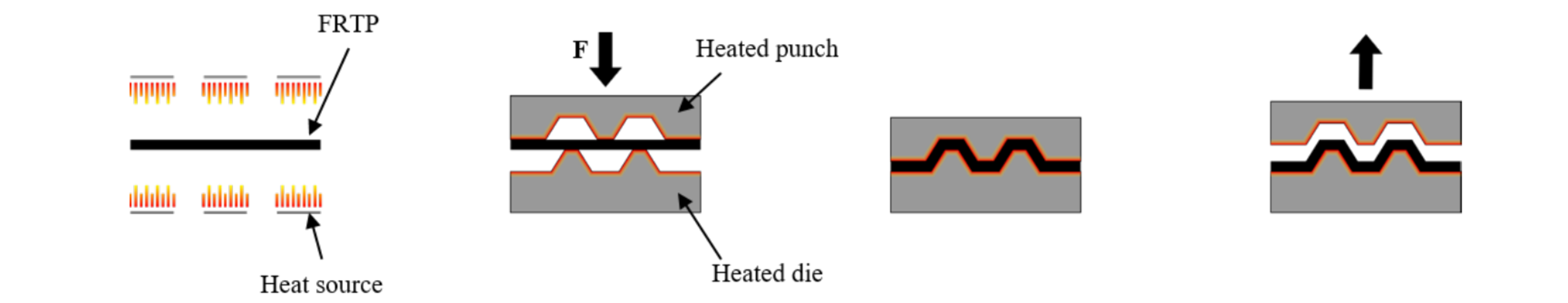
Fig. 1. Thermoforming process of FRTP semi-finished products (e.g. organo sheets). Adapted from [6].
1.2 Types of pseudo-plastic FRTP semi-finished products
To achieve higher degrees of forming of FRTP semi-finished products, the use of discontinuous (and partly recycled or mixed) aligned fibre rovings are suitable approaches. The alignment of the fibres during the production can be achieved by vacuum or centrifugal force. However, these approaches have an increased deviation in fibre alignment than continuous fibre rovings which leads to lower mechanical properties [7,8,9]. Woven organo sheets can also be manufactured using discontinuous fibre rovings. These rovings are aligned and then spun into a continuous yarn using a polyamide 6 (PA6) filament [9]. Regardless of the manufacturing process of FRTP semi-finished products, the approach of discontinuous fibre rovings shows promising potential for improving the forming properties. During a forming process, the discontinuous fibre rovings slide within the viscous thermoplastic matrix. Investigations on the mechanical properties of the organo sheets consisting of discontinuous 25 mm long fibre rovings using a fibre orientation of 0/90 ° showed that the tensile strength is close to conventional organo sheets. In the case of unidirectional material, the tensile strength of discontinuous FRTP semi-finished products is 20 % below continuous fibre semi-finished products. Carbon fibre reinforced polyamide 6 is used for both the organic sheet and the unidirectional material [9]. By increasing the fibre length, an improvement of the mechanical properties can be achieved. However, this reduces the formability and processability of the semi-finished product [7].
In this paper, a novel approach of pseudo-plastic artificially manufactured FRTP semi-finished products is considered. The semi-finished product is manufactured in an adapted tape placement process. Conventional continuous unidirectional fibre reinforced thermoplastic tapes are used. During the tape placement process, the tapes are variably cut to length by a cutting system, which is integrated into the tape laying head. In-plane, the adjacent tape sections in the Y-direction are placed offset by the overlap length LO along the X-direction. Out-of-plane, this layer structure is continued, but shifted by half the tape width WT along the Y-direction to the adjacent layers. The use of discontinuous tapes results sliding surfaces in-plane and out-of-plane. On these surfaces, the tape sections can slide during the thermoforming process and realise higher forming degrees as long as the polymer matrix is in a molten state. Due to the offsets, every fourth layer is identical to avoid holes or imperfections that could be caused by the slipping process. The manufacturing process offers a high potential for the production of pseudo-plastic semi-finished products with high reproducibility and accuracy according to the fibre orientation and the tape positioning. In addition, the semi-finished product can be adapted to the requirements of the component loads and the manufacturing process by the tape length LT and tape overlap length LO.
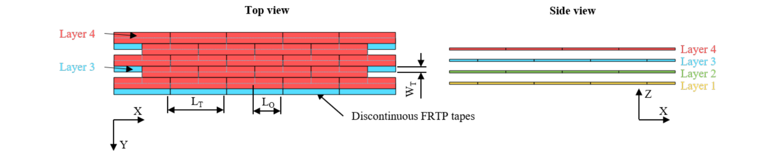
Fig. 2. Design of the pseudo-plastic FRTP semi-finished product consisting of discontinuous tapes.
1.3 Virtual parameter identification
With the novel approach of the pseudo-plastic FRTP semi-finished product consisting of discontinuous tapes, a virtual parameter identification is carried out according to the inverse method. This method describes the procedure for adapting the numerical results to the experimental results. Typical target values can be displacements, forces or strains. In addition, material parameters can be determined with this method. For this purpose, a relevant set of parameters is identified for the fitting. The parameters are adjusted until the difference between the numerical and experimental target values is minimized [10].
With the help of the virtual parameter identification, the relevant parameters for matching the sliding behaviour between the tape sections are identified and determined using a uniaxial tensile test. This offers the possibility to virtually characterise FRTP semi-finished products with arbitrary configurations in terms of tape length and overlap length. Hence, the sliding behaviour of the tape sections and consequently the formability can be predicted yielding an improved prediction quality of thermoforming simulations.
2 Setup for experimental tensile tests
For the virtual parameter identification, experimental tensile tests are carried out with the pseudo-plastic fully unidirectional FRTP semi-finished products in order to obtain force-displacement curves. For these tests, three configurations of the FRTP semi- finished product are examined, which differ in the length of the tape sections as well as overlap area (see Table 1). In addition, the tensile test is modelled numerically and parameters are adjusted to fit the numerical curves. The tensile tests are performed according to DIN EN ISO 527-5 at a tensile speed of 10 mm/min. To characterise the forming behaviour and consequently the sliding of the tape sections, the tests are conducted at a temperature of 230 °C. In addition, an optical measuring system is used to record the sliding behaviour. For this purpose, a stochastically distributed pattern is applied onto the test specimens. Especially in tensile tests with temperatures above the melting point of the polymer matrix, falsified measurement results of the strain can occur due to sliding between the clamps and the test specimen. Such a measurement error can be excluded by the optical measurement of the strain. After completion of the test series, the strains measured by the optical system are matched with the forces determined by the testing machine.
Table 1. Investigated Configurations of the pseudo-plastic FRTP semi-finished product.

Conventional unidirectional E-glass fibre reinforced polyamide 6 tapes are used for the test specimens (Celstran CFR-TP PA6 GF60-01). The fibre volume content is 39 %. The configurations shown above in Table 1 have a fully unidirectional ply structure with the fibres oriented in the direction of the tensile force. The test specimens consist of eight layers with a total thickness of 2 mm.
Fig. 3 shows the force-displacement curves of the three configurations from the experimental tests. It can be seen that the curves show a similar course for the investigated configurations. The maximum force, the displacement at the maximum force as well as the force drop are at comparable levels. Based on the findings, the configuration parameters tape length LT and overlap length LO have only small influence on the course of the curves. The small deviation between the curves of the three configurations may be due to temperature deviations between the test specimens during the test as well as production-related influences of the semi-finished product, such as air inclusions. The polyamide 6 matrix exhibits a viscous state at a test temperature of 230 °C. Due to this, the viscous matrix can only insufficiently transmit the forces between the tape layers, as the binding forces between the molecular chains are softened. This results in a sliding of the entangled molecular chains of the polyamide 6 and therefore of the tape sections.
The evaluation of the optical measurement images shows that initially there are no sliding effects between the tape sections within the test specimen. The specimen is uniformly strained up to the maximum force. Higher forces cannot be transmitted by the viscous polyamide 6 matrix between the tape sections. When the critical strain is exceeded, sliding occurs, which can be seen from the force drop and the subsequent constant force level in the force-displacement curve.
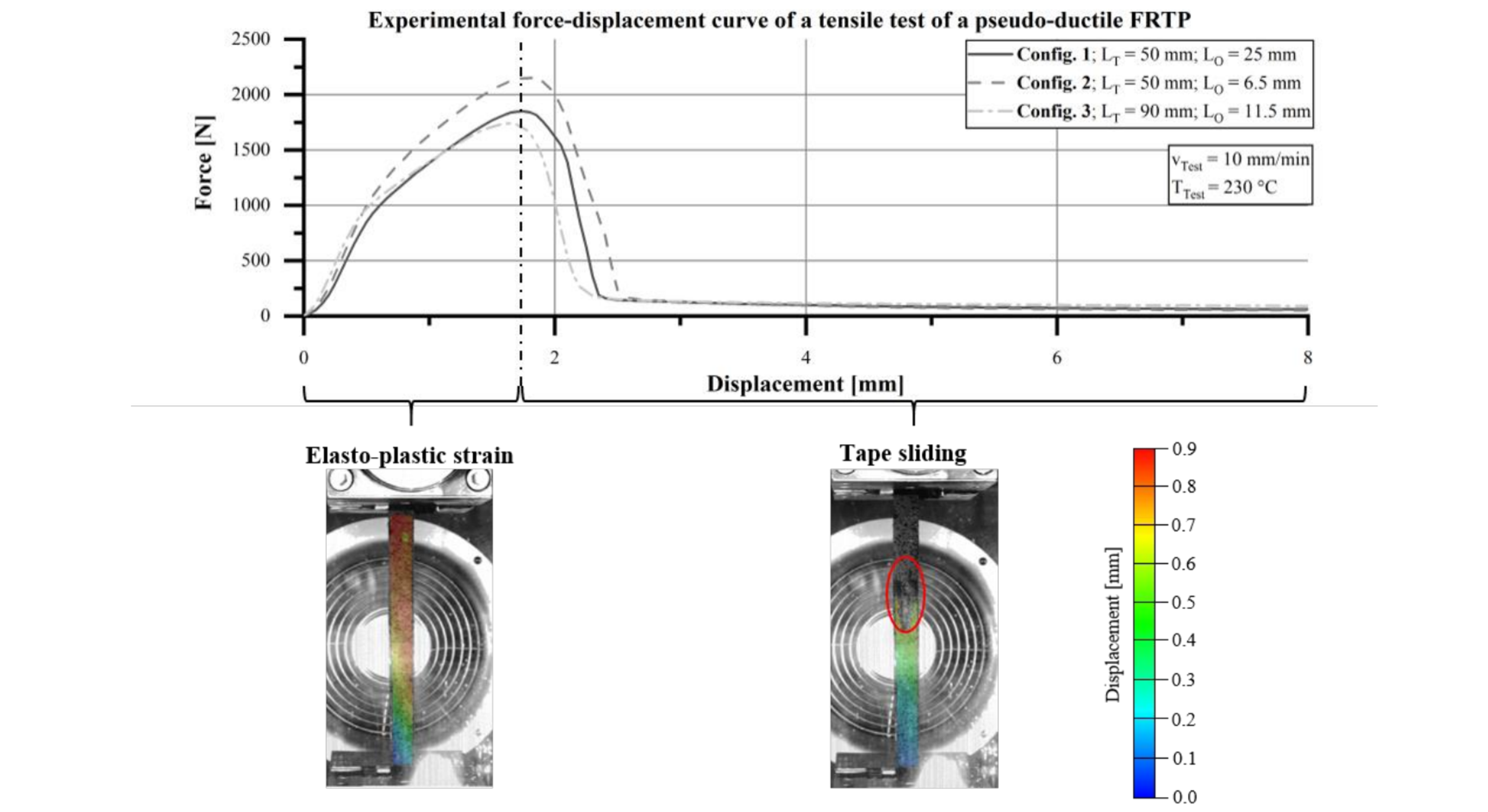
Fig. 3. Experimental mean force-displacement curves of the tensile tests of the pseudo-plastic FRTP.
3 Numerical model
The numerical modelling of the uniaxial tensile test is carried out in the finite element software LS-Dyna. A model is created for each of the three configurations. The structure of the models follows the layer structure of the configurations in Table 1. The tape sections are discretised with linear shell elements representing a layer thickness of 0.25 mm. The total distance of the specimen in the model is 200 mm corresponding to the gauge length in the experiments. Boundary conditions are defined at the nodes at both ends of the model. The first constraint prohibits rotational and translational movements around all the axes. With the second constraint, only a translational movement in the tensile direction is permitted. The simulation is displacement-controlled by a defined linear increasing displacement-time curve. The specimen thickness in the model is 2 mm (8 layers).
The material model MAT_249_REINFORCED_THERMOPLASTIC is used for the tape sections, which represents a material model for fibre reinforced thermoplastics. The fibres are modelled as anisotropic-hyperelastic and the matrix material as elasto-plastic [11]. The elastic tensile stresses within the fibres:

is defined by the stress of the endless fibre reinforcement of the tapes fi(λi) with respect to the fibre stretch λi and the fiber orientation mi for fibre family i. The Jacobi determinant is denoted as J. The total stress of the composites is then computed as:

the sum of the stresses in the matrix σm and the fibres σf. However, the stresses of the matrix can be neglected because the material is in the molten state.
The fibre orientation is defined along the loading direction (0 °). As input, stress-strain curves of unidirectional continuous fibre laminates at a test temperature of 230 °C in longitudinal (0 °) and transverse (90 °) fibre direction are given.
For each layer of the specimen a PartSet is created to define the contact between the planes by "AUTOMATIC_ONE_WAY_SURFACE_TO_SURFACE". The interaction between the tape sections within a layer is neglected. The experimental force-displacement curve of the tensile tests shows a high level of agreement with the curve of a tribology test for determining static and dynamic friction coefficients. Based on this finding, the numerical model is fitted to the experimental data with these two parameters [12]. In LS-Dyna, the friction coefficient:

depends on the static friction FS, dynamic friction FD, exponential decay coefficient DC as well as the relative velocity vrel [13]. In addition, the friction force can be limited by a coefficient for viscous friction VC. The exponential decay coefficient and coefficient for viscous friction are assumed to be constant. For this purpose, the numerical and experimental force-displacement curves are compared and the friction parameters adjusted iteratively until the curves match sufficiently well. For fitting, the averaged curve from the three configurations of the experimental tests is used.
4 Results
Fig. 4 shows the numerically determined force-displacement curves for the three configurations with the selected friction parameters in comparison to the averaged experimental curve. The aim was to achieve a high correlation between the numerical and experimental force-displacement curves by adapting the friction parameters in the simulation model in order to predict the sliding behaviour of the tape sections.
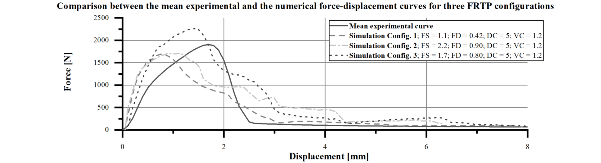
Fig. 4. Comparison of the experimental and numerical force-displacement curves including the corresponding friction parameters from the virtual parameter identification.
It is observed that the numerical force-displacement curves have a comparable course to the experimental data. First, the force increases a maximum and then falls until it converges. This underlines the assumption that the force-displacement curves can be adjusted by the friction parameters in the simulation model. Furthermore, it can be seen from the simulation results that the rise of the curve to the maximum force is steeper. The subsequent drop in force is also flatter compared to the experimental force- displacement curve. This results in a smoother transition from the force drop to the constant force value. The correlation coefficient as well as the mean squared error normalised to the number of data points given in Table 2 is determined to assess the quality of the agreement between the numerical and the experimental force-displacement curve.
Table 2. Correlation and mean squared error between the numerical and experimental force-displacement curve.

The normalisation of the mean squared error is defined according to (4).

The normalised MSE increases the comparability between the three configurations, since the number of data points of the force-displacement curves depends on the initial overlap length of the tape sections. For instance, configuration 2 has a shorter force-displacement curve than configurations 1 and 3. For a better visualisation of Fig. 4, the force curve is shown up to a displacement of 8 mm.
From the results, it can be seen that a high positive correlation between 0.82 and 0.91 and low mean error of 0.11 and 0.17 kN2 can be achieved between the experimental and numerical force-displacement curves. However, the mean error also indicates that, in addition to the friction coefficients, other parameters must be taken into account in order to achieve a higher degree of agreement between the curves. For example, modifications in the material model, such as stiffness, are necessary to improve the matching of the force increase. In addition, the force-displacement curve can be influenced by the exponential decay coefficient and coefficient for viscous friction.
To fit the numerical force-displacement curves, the friction parameters had to be adjusted for each configuration and are therefore not constant. It shows that a shorter overlap length with constant tape length leads to higher friction parameters (comparison between configuration 1 and 2). If the overlap length is increased and the ratio between the overlap length and the tape length remains constant, the parameters must be set slightly lower (comparison between configuration 2 and 3). However, in order increase the significance about the dependency of the friction parameters and the tape length as well as overlap length, further finer gradations of these two configuration parameters must be made in the simulation. This offers the possibility to make predictions about the setting of the friction parameters depending on the selected configuration parameters in order to achieve a high prediction quality of the sliding behaviour.
Fig. 5 shows the comparison of the sliding process from the simulation and the experiments. A high degree of agreement between the sliding of the tape sections is observed here.
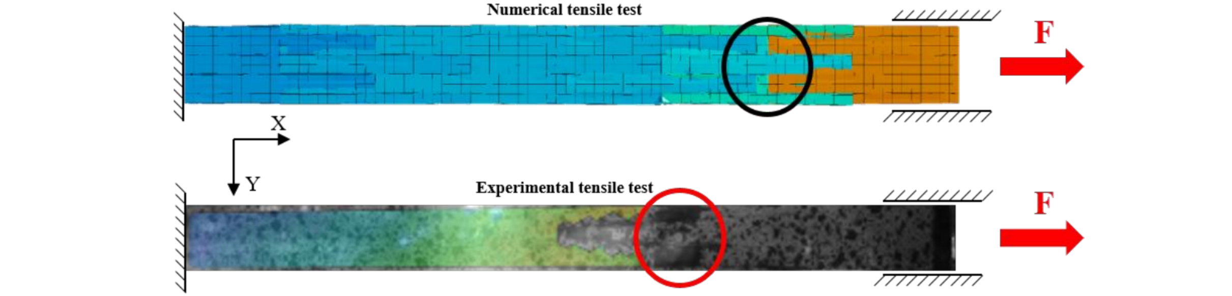
Fig. 5. Comparison of the sliding behaviour and the X-displacement of the tape sections between the numerical and experimental tensile tests.
5 Conclusion
In this paper, a virtual parameter identification was carried out by means of to the inverse method for the forming behaviour of a pseudo-plastic FRTP semi-finished product. The FRTP semi-finished product consists of discontinuous tapes. The sliding of the tape sections results in a pseudo-plasticity and improved formability of the FRTP semi-finished product. To determine the pseudo- plastic behaviour uniaxial tensile tests at a temperature of 230 °C were carried out with the FRTP semi-finished product variating the tape length and overlap length. The force-displacement curves show that the FRTP semi-finished product initially strains uniformly. As soon as a critical strain is reached, the tape layers start to slide, resulting in a force drop until a constant force level is reached. A numerical tensile test with the same configurations from the experimental tests was set up to perform a virtual parameter identification manually. By adjusting the friction parameters in the simulation model between the pile layers, the force- displacement curve is fitted to the experimental data. There is a good correlation between the numerical and experimental curves of up to r = 0.91. However, for a more accurate material description, further parameters have to be taken into account to achieve a better agreement with the experiments. Due to the large number of other possible parameters for the virtual parameter identification, an automated optimisation routine is required. In addition, the friction parameters had to be set differently for the three configurations of the FRTP investigated. In order to determine the influences of the friction parameters on the force-displacement curve as a function of the configuration parameters, finer gradations of the configuration parameters (tape length and overlap length) must be made in the simulation model. Further experimental tests are not necessary, as it could be shown that the tape length and overlap length have small influence on the course of the force-displacement curve. However, the maximum sliding length can be significantly influenced by the configuration parameters. In this way, an improved prediction accuracy of the friction parameters can be achieved for any configurations.
Acknowledgements
The authors gratefully acknowledged the financial support of the ZIM cooperation project ZF4096706, which is supported by the AiF within the program Zentrales Innovationsprogramm Mittelstand (ZIM) of the Federal Minitry of Economics and Technology. Furthermore, the authors would like to thank NRC, NUCAP and Compositence GmbH for the outstanding cooperation.
[1] Uddin, N. Developments in Fiber-Reinforced Polymer (FRP) Composites for Civil Engineering. Woodhead Publishing, 2013.
[2] Behrens, B.-A. Raatz, A. Hübner, S. Bonk, C. Bohne, F. Bruns, C. Micke-Camuz, M. Automated Stamp Forming of Continuous Fiber Reinforce Thermoplastics for Complex Shell Geometries. Procedia CIRP, 2017, 66, p. 113-118.
[3] Dröder, K. Prozesstechnologie zur Herstellung von FVK-Metall-Hybriden. Springer-Verlag, 2020.
[4] Injection moulding with organic sheets – more function with less weight, https://www.poeppelmann.com/en/k-tech/competences/technologies/injection-moulding- with-organic-sheets/, 07.12.2020. [4] Okine, R.-K. Edison, D.-H. Little, N.-K. Properties and Formability of an Aligned Discontinuous Fiber Thermoplastic Composite Sheet. Journal of Reinforced Plastics and Composites, 1990, 91, p. 70-90.
[5] Kabala, P., Demes, M., Bienia, S., Huerkamp, A., Beuscher, J., Dröder, K. Numerical model of an integrated deep-drawing and thermoforming process. MERGE 2019, 2019.
[6] Thermoforming, BOND LAMINATES | Thermoforming (bond-laminates.com), 07.12.2020.
[7] Such, M. Ward, C. Potter, K. Aligned Discontinuous Fibre Composites: A Short History. Journal of Multifunctional Composites, 2014, 3, p. 155-168.
[8] Yu, H. Longana, M.-L. Jalalvand, M. Wisnom, M.-R., Potter, K. Hierarchical pseudo-ductile hybrid composites combining continuous and highly aligned discontinuous fibres. Composites: Part A, 2018, 105, p. 40-56.
[9] Goergen, C. Baz, S. Mitschang, P. Gresser, G.-T. Highly Drapable Organic Sheets Made of Recycled Carbon Staple Fiber Yarns. 21 st International Conference on Composite Materials, 2017.
[10] Cooreman, S. Lecompte, D. Soll, H. Vantomme, J. Debruyne, D. Elasto-plastic material parameter identification by inverse methods: Calculation of the sensitivity matrix. International Journal of Solids and Structures, 2007, 44, p. 4329-4341.
[11] ST, 2020. LS-DYNA keyword user’s manual - Volume II. r12 ed. 2020.Livermore Software Technology Corporation.
[12] Lee, C.-H. Polycarpou, A.-A. Static Friction Experiments and Verification of an Improved Elastic-Plastic Model Including Roughness Effects. Journal of Tribology, 2007, 129, p. 754-760.
[13] ST, 2020. LS-DYNA keyword user’s manual - Volume I. r12 ed. 2020.Livermore Software Technology Corporation.
