1 Introduction
Due to their combination of good electrical conductivity and good machinability, CuZn-alloys with lead contents from mPb=1 % to mPb=4 % are a preferred workpiece material in the manufacture of electronic components such as connectors due to their excellent productivity in machining. Since lead is harmful to human health and to the environment [1], multiple legislative initiatives have been installed to drastically reduce the amount of lead in copper alloys. For electronic components, most international legislation follows the European “Restriction of Certain Hazardous Substances” (RoHS) directive in allowing a maximum of mPb< 0.1 % in the future [2,3,4]. Similar legislation is in place for other applications such as toys, jewellery, motor vehicles or drinking water components or currently being expanded to all applications with the European REACH-directive [5].
Therefore, lead-free CuZn-alloys have to be used for the production of electronics components in the future. Compared to the popular leaded alloy CuZn39Pb3 (mPb=3 %), machining of lead-free CuZn-materials results in higher cutting force components, longer chip forms, increased friction and much higher adhesive and abrasive tool wear [6,7,8]. This leads to a crucial reduction in process reliability and productivity in all machining processes. Nevertheless, systematic tool and process design has lead to major improvements for turning and drilling processes [6,7]. Milling of lead-free CuZn-materials with small tool diameters (d<5 mm) has not yet been examined systematically. Research regarding plunge milling of different workpiece materials suggests maximising the cutting force component axial to the tool in relation to radial force components. This minimizes tool deflection and can be achieved by utilizing tools with small cutting corner radii rε , small feeds f and large pitches p [9].
The plunge milling process examined in this work is typical for the manufacture of rectangular inner shapes in electronic terminals but is also relevant for the manufacture of miscellaneous components for such as valves, hydraulic components and dies. In electronics, rectangular holes are produced by drilling as a first step. This is followed by one or more plunge milling operations that use a shank tool with an axial feed. The kinematics are therefore the same as in drilling except for the interruption of the cut. The pitch direction is straight so that the tool contact angle exceeds Φc = 180 °. The diameters of plunge milling tools for this application typically range between 1.5 mm ≤ d ≤5 mm with a depth of up to 10 times the tool diameter d. Tight tolerances (Δx ≤ 0.05 mm) for the geometry of the plunge milled channel are needed to provide sufficient guidance for the finishing broaching process since the broach has low stiffness.
The combination of the machining characteristics of lead-free brass and the long and thin plunge milling tools leads to high tool deflection and, therefore, reduced workpiece quality. The effects of the workpiece material and tool geometry on the cutting force components and offset of the plunge milled channel were examined in this paper. The outcomes of this study provide the base for further optimization of tool and process design in plunge milling of lead-free brass alloys.
2 Workpiece material characterization
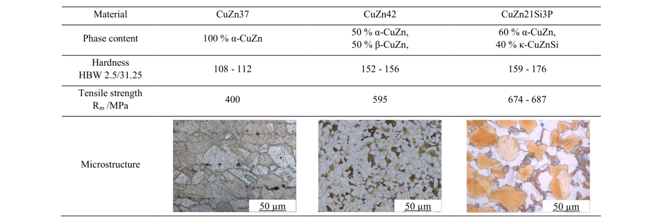
The three materials differ in their chemical composition and subsequently in their microstructure (Table 1). CuZn37 is a binary brass with nearly 100 % α-CuZn-Phase provided by Diehl Metall. The cubic-face-centred α-Phase is relatively soft and ductile in comparison to the body-centred-cubic β-Phase which occurs in brasses with zinc contents above m Zn > 37 %. The CuZn42 material was provided by Aurubis and has a β-Phase content of φβ = 50 %. The alloy CuZn21Si3P was provided by Wieland Werke and contains about φα = 60 % α-Phase. The additional φκ = 40 % of the hard and brittle κ-Phase contains Silicon. Also, trace amounts of the intermetallic γ-Phase are present. All materials were delivered in the form of rods that were produced by continuous casting, extrusion and cold drawing to a diameter of d = 10 mm. Due to this production process, the materials had strain hardening towards the edges of the rods with a depth of less than one millimetre. The maximum hardness differential due to this occurred in the CuZn21Si3P material (Table 1). All experiments were conducted with a minimum of one millimetre distance to the surface in mostly homogenous workpiece material.
Table 1. Workpiece material composition, phase content and microstructure.
3 Experimental setup
The machining tests were performed on a four-axis-milling machine NHX 5000 from DMG MORI (Fig. 1 a). Cylindrical workpieces with a length of L=14 mm and a diameter of D=10 mm were used for all tests. These were mounted in a purpose-produced, lightweight chucking device on a piezoelectric three-component dynamometer Type 9119AA2 from the manufacturer Kistler. The sampling rate of the A/D-converter was set to fs=1000 Hz. The workpiece face was milled flat in order to reduce tool drift upon entry. Two through bores were drilled in the circular face of the workpiece (Fig. 1b). These were then used as the starting point of a series of four plunge milling cuts on each side. The diameter of the plunge milling tools and the through bores was d=2 mm. The plunge milling was performed through the entire length of the workpieces of L=14 mm. This resulted in a length-diameter-ratio of L/D=7. The sets of side-by-side series of cuts per workpiece were performed with constant cutting parameters as a repeat experiment. Flood cooling with the lubricoolant Vasco TP 519 from Blaser Swisslube with a concentration of 5.8 % was used for all experiments.
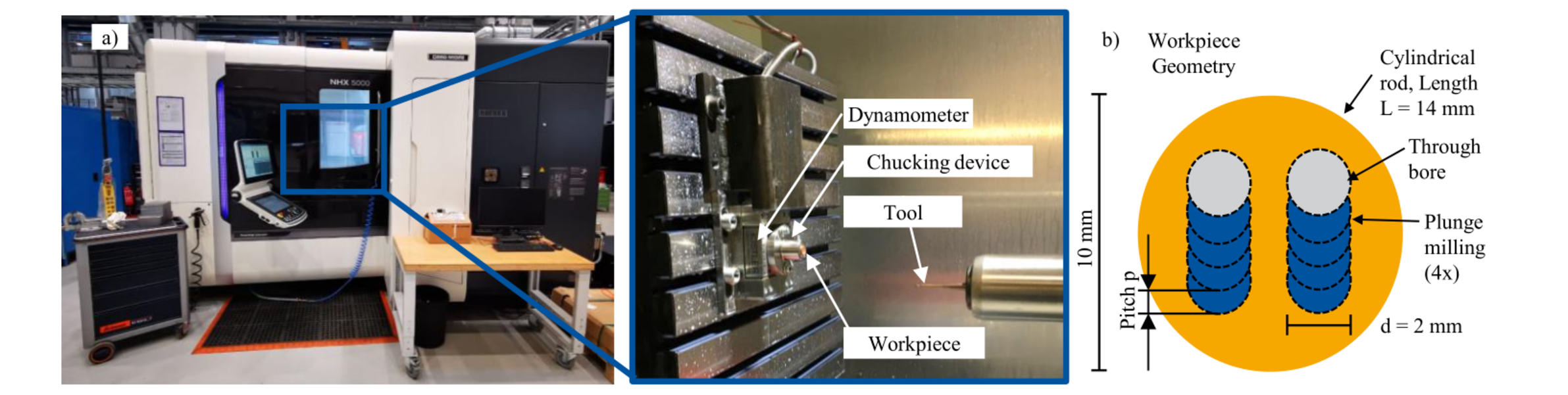
Fig. 1. (a) Experimental setup and (b) workpiece geometry.
Similar to the width of cut ae in conventional milling, the pitch p describes the radial distance between the axial plunge milling cuts and was varied from p=0.2 mm to p=0.5 mm. The feed per tooth was varied from fz=0.015 mm to fz=0.03 mm with a constant cutting speed of vc=50 m/min. These parameters reflect common industrial applications in the electronics industry with the leaded free-machining brass CuZn39Pb3. The experiments were conducted with all three workpiece materials, CuZn37, CuZn42 and CuZn21Si3P (Table 2).
Table 2. Workpiece materials and cutting parameters.

The offset of the plunge milled channels was measured using an incident light microscope type VHX-5000 from the company Keyence. The radial offset Δx of the milled channel was used as a measure for the tool deflection. It is represented by the difference between the target and the actual centerpoint of the last plunge milled channel (Fig. 2). The measurements were taken at the tool exit side due to the milled channel being offset along its length. All measurements were repeated once in order to increase validity. Due to the manual placement of the references, a measurement uncertainty of about five µm remains. A 3D measurement of the internal workpiece structure was not possible due to frequently occurring burrs in the cavities.
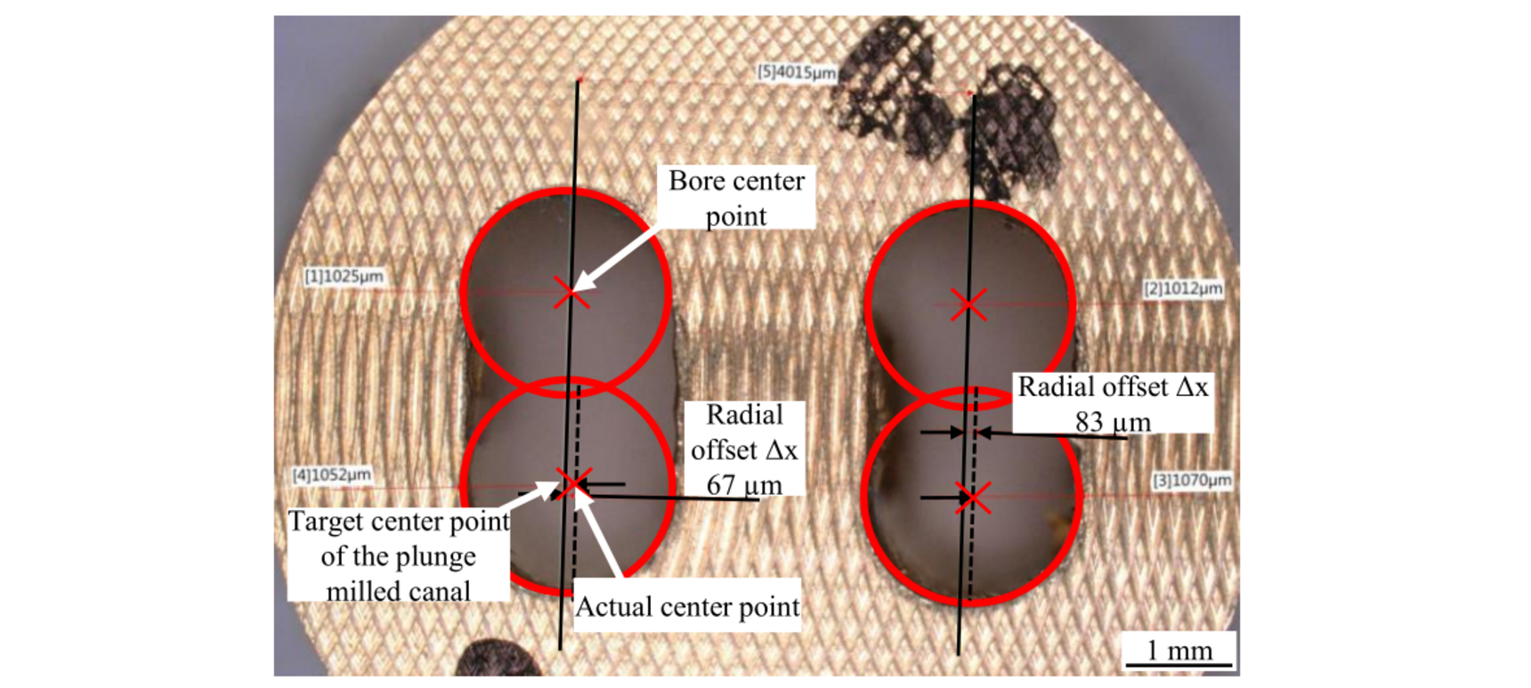
Fig. 2. Measurement of plunge milled channel displacement in microscope.
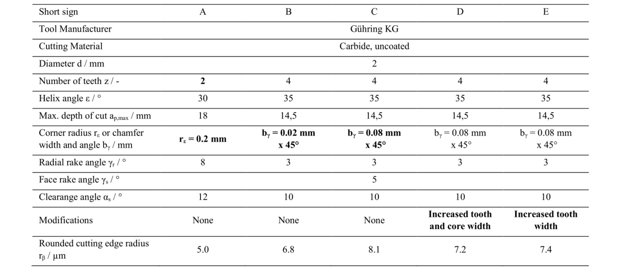
The company Gühring KG provided five different uncoated carbide tools with a tool diameter of d=2 mm for the experiments (Table 3). Tool A was a standard tool with two cutting edges and a corner radius of rε=0.2 mm. Tools B to E were variations of the special tool C with z=4 cutting edges. Tool B was fitted with a smaller chamfer width of bγ=0.02 mm compared to bγ=0.08 mm in the other variations in order to evaluate the influence of the chamfer on workpiece accuracy. In order to increase tool stiffness, tools D and E were designed with broader teeth. Tool D additionally had a larger shaft diameter. Both of these measured reduced the size of the inner flutes. The rounded cutting edge radius rβ was measured using the stripe light projection microscope MicroCAD from the manufacturer GFM Messtechnik.
Table 3. Tool Geometry.
4 Experimental results and analysis
The experiments were analyzed using the measurements of the cutting force components and the offset of the plunge milled channel Δx. The results of the force measurements were similar to those common in drilling [10]: After the entry of the tool into the workpiece, the radial cutting force components Fx and Fy increased steadily and reached a peak when the tool reached the end of the workpiece. This was caused by a reduction of lubrication as the tool progressed and built-up chips in the inner flute. Therefore, the evaluation of the axial force component Fz and the two radial components Fy (in direction of pitch) and Fx (orthogonal to pitch direction) was carried out using their respective maximum values (Fig. 3a).
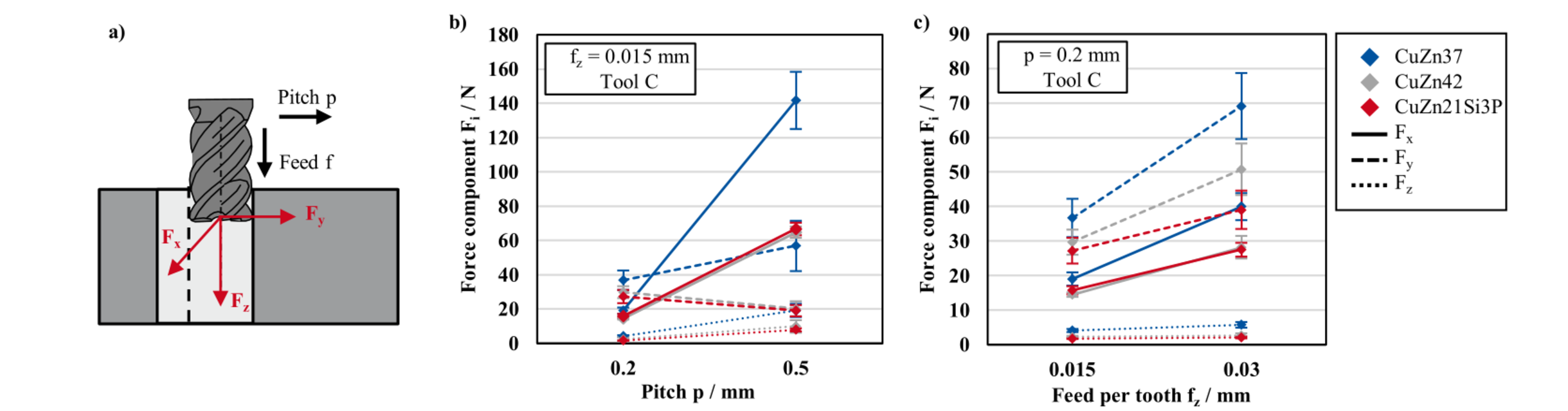
Fig. 3. (a) Orientation of the force components and force components depending on pitch p (b) and feed per tooth fz (c) in plunge milling of CuZn37, CuZn42 and CuZn21Si3P at vc=50 m/min.
Generally, the force components measured when milling CuZn37 were highest followed by CuZn42 and CuZn21Si3P as the lowest (Fig. 3b and c). These differences were caused by the more ductile chip formation with higher chip compression in machining of CuZn37 in comparison to the typically partially (CuZn42) or fully segmented chip formation in cutting of CuZn21Si3P [6,7]. The radial force components Fx and Fy were between three and ten times higher than the axial Fz. This is disadvantageous for plunge milling since it causes tool deflection. Ideally, all the cutting forces would be in the axial Fz direction. Increasing the pitch p from p=0.2 mm to p=0.5 mm augmented Fx and Fz components for all materials (Fig. 3 b). This was due to the larger chip cross-section. The growth of the force was close to proportional to the increase in pitch for CuZn42 and CuZn21Si3P but it was about two times higher for CuZn37. This was explained by the higher tendency to adhesion between tool and workpiece material and more chip build-up in the inner flute of the tool in CuZn37 compared to the other workpiece materials [7]. Raising the pitch led to decreasing cutting force components Fy in the direction of the pitch due to a smaller proportion of the effective cutting width being in the area of the corner radius. Additionally, the larger tool contact angle of Φc=208.9 ° at p=0.5 mm in comparison to Φc=191,5 ° at p 0.2 mm reduced the oscillation of the tool tip which led to lower forces in the Y-direction. This did not apply to the plunge milling of CuZn37 due to the high amounts of built-up chips in the tools inner flutes. For CuZn37 doubling the feed per tooth from fz=0.015 mm to fz=0.03 mm increased all cutting force components (Fig. 3 c). Due to higher friction, that growth was stronger in plunge milling of CuZn37 and CuZn42 than with CuZn21Si3P.
The influence of the tool geometry on the radial cutting force component F x and the tool path offset Δx was analyzed with the same four sets of cutting parameters regarding pitch and feed per tooth at a constant cutting velocity of vc=50 m/min (Fig. 4). The correlation coefficients between the radial force Fx and the tool tip displacement Δx in Fig. 4 suggested a rather strong correlation between these measurements. The number of only four parameter points per tool limited the accuracy of these correlations due to clustering of points at the lower end of the line. This relation of force to displacement corresponds to the tools bending stiffness. Using the largest chip cross-section (p=0.5 mm and fz=0.03 mm), the tools with thickened shafts and teeth C, D and E broke due to insufficient chip evacuation. This indicated that the inner flutes of these tools were not sufficiently large for the amount and size of chips formed. Tool A shows the highest ratio of force Fx to displacement Δx, which was explained by its longer projection length than tools B to E which led to lower overall stiffness. Due to having two cutting edges instead of four in tools B to E, chip evacuation was not a problem with tool A. This was the reason that milling with tool A resulted in lower force components Fx and offsets Δx at higher cutting parameters in comparison to the other tools despite having a corner radius rε = 0.5 mm much larger than the chamfers bγ≤0.08 mm of the other tools.
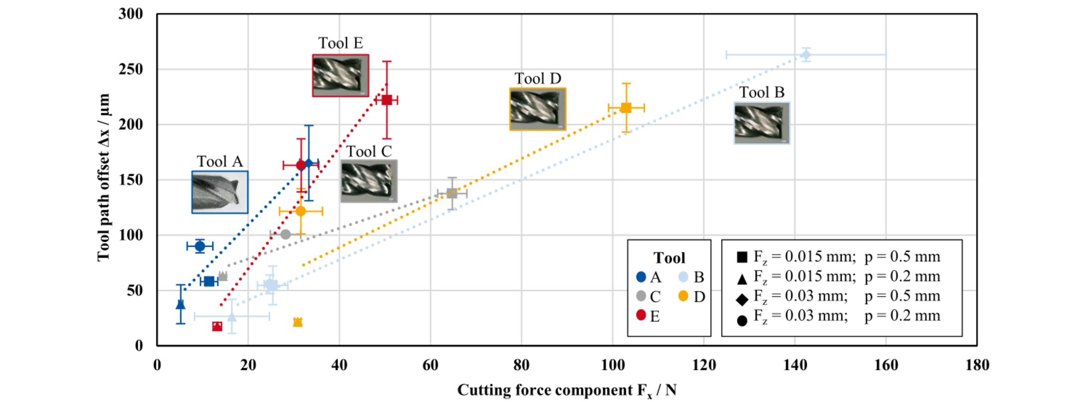
Fig. 4. Correlation between the offset of the plunge milled path Δx and the corresponding cutting force component Fx in plunge milling of CuZn42 with multiple tools at vc=50 m/min.
With a pitch of p=0.2 mm, tool B produced lower offsets and on average slightly lower force components Fx as tool C (Fig. 4). This was due the smaller portion of radial engagement at the tools corner. At the higher pitch p=0.5 mm, only a small offset was produced with tool B. It was the only variation of tool C that did not break due to chips jammed in the inner flute at p=0.5 mm and fz=0.03 mm. There was no additional tool breakage during the experiments. Tools D and E were intended to increase the stiffness of the tool compared to the reference tool C by increasing the width of the core (Tool D) and teeth (Tools D and E). The higher theoretical stiffness of these tools only reduced the offset of the milled channel at fz=0.015 mm and p=0.2 mm. In the case of tool D, the force Fx was much higher than with tool C and D at those parameters due to friction of the chips in the small inner flutes of the tool. In conclusion, improving chip evacuation was the main influence factor on reducing tool deflection and tool breakage. This resulted in the tool A with the lowest number of teeth (z=2) providing the lowest radial offset in plunge milling. The variations of tool C showed that increasing the tool stiffness by strengthening the teeth (Tools D and E) was counterproductive due to the worse chip evacuation through these tool’s smaller inner flutes.
5 Conclusions
The overall objective of this research was to identify the influence of tool geometry, workpiece material and cutting parameters on cutting forces and tool deflection in plunge milling of the lead-free CuZn-alloys CuZn37, CuZn42 and CuZn21Si3P. Therefore, cutting tools with specific geometric features were investigated at multiple cutting parameters in this work. Reducing the width of corner chamfers lowered tool tip displacement. Due to the small dimensions of the cavities and the tools inner flutes, chip evacuation had a stronger influence than the corner design in this application. Tools with large inner flutes showed less tool tip deflection than tools with increased stiffness and smaller inner flutes due to friction between chips in the inner flutes and the workpiece. At low cutting parameters, a minor influence of tool stiffness on the tool deflection was identified. An ideal tool would have large inner flutes and small corner chamfers. The experiments also showed that the cutting force components strongly depend on the material because of differences in chip formation and friction of chips between the inner flute and the cavity walls.
Acknowledgements
The IGF-Project 20029 N of the research association „Stifterverband Metalle e. V.“ was supported via the AiF within the funding programme “Industrielle Gemeinschaftsforschung (IGF)" by the Federal Ministry of Economic Affairs and Energy due to a decision of the german parliament.
