1 Introduction
Stacked metals-FRP materials are increasingly employed in many industries such as automotive, railways and aerospace due to the dual properties offered by these materials: lightweight and mechanical resistance. In addition machining process and especially drilling, which is the more common machining operation used for these kind of net-shaped material, can cause a large range of issues: delamination of the composite part by peel up or push up [1], burrs and tearing especially at the exit [2], vibrations [3] and large tool wear [4] due to the changing machining properties between composite and metal [5]. The knowledge of the cutting force and torque is a key point to avoid all these previous problems. It allows comparing it with a critical thrust force and torque for delamination and crack or to establish limit parameters to prevent tool wear and vibrations.
Since 1950s a lot of research works has been carried out to model cutting force for the basic metal machining operations. The Merchant’s [6] model of the orthogonal cutting forces by shear plane modeling is the basis for many other models specific to each machining operation. Firsts drilling force models for metals were introduced in 1970s and can be divided into two categories [7]: some using an iterative theoretical energetical pattern based on the shear plane zone theory by assuming that the mechanical properties are known, while some others prefer to use experimental approaches thanks to empirical parameters giving more accurate results. Most of them are based on a 3D spatial discretization combined with oblique cutting or simplified quasi-orthogonal cutting theory and are tool and material specific.
This paper present a new drilling cutting force and torque algorithm developed for stacks metal-FRP by using Chandrasekharan and al.’s [8,9] and Langella and al.’s [10] theories which is able to predict with a reduced number of drilling tests accurate non-tool dependent values of the empirical input parameters thanks to a reverse least squared minimisation method.
2 Stack cutting force and torque modelling
Common architecture for metals and composites
The suggested model is based on a dual discretization in order to highlight the thrust force and torque value:
-
A spatial discretization of the cutting edge is set up as shown in figure 1 inspired from Chandrasekharan and al.’s model [8]. Twist drill cutting edges are decomposed in two main parts: chisel edge (central part) and cutting lips (peripheral part) where the cutting phenomena and parameters differ according to the material type and location (described below). The concerned edges are divided into 𝑁𝑑 elements of length 𝑑𝑦 (mm) in which the infinitesimal force 𝑑𝐹⃗z and torque 𝑑C⃗ are computed, the total drilling thrust force 𝐹⃗𝑧 and C⃗ are then given by the following sums (1) and (2) multiplied by x, the number of cutting lips (2 in this work):

The radial coordinate 𝜌(𝑟)=𝑟/𝑅 of each spatial element 𝑛𝑑 is previously necessary to determine the location of the elements (chisel edge of cutting lips) and thus calculate the drilling force by an appropriate equation.
-
A time discretization is also required to obtain the drilling cutting force value in function of the time trough the different materials crossing phases (figure 2) contained in a drill test. The total drilling time 𝑇𝑡 (s) of an operation is divided into 𝑁𝑡 steps of a time length 𝑑𝑡 wich gives total cutting force matrices 𝐹⃗(𝑁𝑡) and C⃗(𝑁𝑡). The vertical position 𝑍𝑅𝑝(𝑡) of a reference point 𝑅𝑝 placed on the center of the twist drill is computed at each time steps and allows to obtain the position 𝑍𝑒𝑙𝑒𝑚(𝜌,𝑡) of a spatial element located in the chisel edge or in the cutting lips by geometric knowledge of the twist drill. Knowing the vertical position of each cutting edge element then makes it possible to determine the material in which it is located and set the appropriate theoretical cutting force model for the element thanks to the positioning of boundary 𝑧1,𝑧2,𝑧3 at the border of each material.
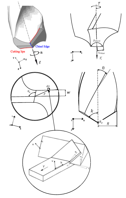
Fig. 1. Geometrical parameters and spatial discretization of a twist drill
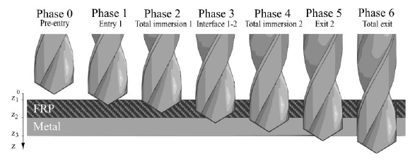
Fig. 2. Temporal steps of a standard drilling operation for a FRP-metal stacks
As previously mentioned the cutting mechanisms (as well as its mathematical descriptions) taking place in the cutting lips and in the chisel edge are different. This distinction can be explained by the geometric difference and the orientations of the two types of cutting edges:
-
The orthogonal cutting theory is used for chisel edge (with a large negative rake angle) thanks to its radial orientation (which induces that the cutting speed of each discretized edge element will always be orthogonal to its edge direction).
-
Cutting lips are not radial and the cutting speed of each discretized edge element is not orthogonal to the cutting edge, this explains why oblique cutting theory (more complex three dimensional problem) is used for this geometric part (this induces the introduction of an inclination angle 𝑖 between the normal direction to cutting speed and the cutting edge).
Cutting forces are then specifically given according to the material, cutting conditions, the tool parameters and cutting zone by Chandrasekharan and al.’s [8] equations (3) and (4) for metals and by Langella and al.’s [10] equations (5) and (6) for UD (unidirectional) FRP:

With 𝐾𝑛, 𝐾𝑡, 𝐾𝑣, 𝐾ℎ called respectively the normal, tangential, vertical and horizontal specific pressure given by equations (7), (8), (9), (10), themselves depending on 8 empirical parameters 𝑎𝑛, 𝑎𝑡, 𝑏𝑛, 𝑏𝑡, 𝑐𝑛, 𝑐𝑡, 𝐶𝑛, 𝐶𝑡 for metals and 4 parameters A, B, C, c for UD FRP.

These assumptions lead to a global algorithmic structure developed on MATLAB, which can, from the different parameters of the standard tool (𝜃, 𝜃𝑐, 𝑘, 𝑅, 𝑃𝑐ℎ𝑖𝑠𝑒𝑙, 𝑤), of the cutting operation (feed 𝑓, rotation speed 𝑛), of the discretization (number of time 𝑁𝑡 and spatial increment 𝑁𝑑) and of the stacks configuration (thickness of each layer, order of drilled materials and empirical parameters linked to the specific pressure), return plots and analytical results of the total thrust force and torque induced trough time.
3 Reverse model
Finding the associated material parameters can be a hard and specific task especially with energetical and shear plane methods. The choice of the two previous macroscopic cutting force models using empirical parameters has been made consequently taking into account the efficiency and the facility to obtain reliable results. Furthermore many methods can be used to finds these parameters: for instance Chandrasekharan and al. [8,9] use experimental turning tests (orthogonal cutting) while Langella and al. [10] apply experimental drilling tests by approximation using an average constant rake angle α𝑛,𝑚. The most common problem of using these drilling tests methods is the large tool dependency of the results and the number of experimental tests to be performed to ensure reliability on a large range of cutting parameters. On the other hand applying the turning tests or orthogonal cutting methods for unidirectional FRP is difficult to implement in practise and will not provide efficient results due to the dependence on the fibre’s orientation while this drilling method does not take it into account.
In order to solve these problems a least squares function has been developed which allows to find an approached value of the empirical parameters by minimisation of experimental drilling forces tests carried out on each of the material separately. The least squared function is obtained considering respectively the metal’s and FRP’s empirical parameters 𝑎𝑛, 𝑎𝑡, 𝑏𝑛, 𝑏𝑡, 𝑐𝑛, 𝑐𝑡, 𝐶𝑛, 𝐶𝑡 and 𝐴, 𝐵, 𝐶, 𝑐 as variables to optimize into the following expression:
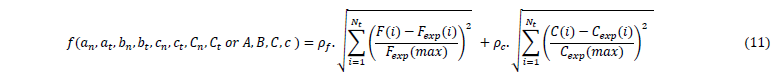
With 𝐹(𝑇𝑡) and C(𝑇𝑡) respectively the force and torque in function of the empirical parameters obtained thanks to the previous algorithm (section 2), 𝐹𝑒𝑥𝑝(𝑇𝑡) and 𝑇𝑒𝑥𝑝(𝑇𝑡) the measured force and torque matrices of experimental drilling test, 𝐹𝑒𝑥𝑝(𝑚𝑎𝑥) and 𝑇𝑒𝑥𝑝(𝑚𝑎𝑥) the measured maximum force and torque (this parameters allows to obtain a dimensionless function), 𝜌𝑓 and 𝜌𝑡 the weighting factors which makes possible to give more importance to one test than another, and 𝑇𝑡 the total time of the drilling test. By choosing carefully an efficient iterative minimization method (e.g. the MATLAB fmincon() constrained minimization function using the interior point algorithm which is able to work with a large number of parameters) this reverse technique can offer many advantages: an efficient, robust and uniform method able to obtain the necessary parameters thanks to a few tests (see section 4 below) without any variables approximation. The least squared method allows to find accurate results even with large measuring noise and makes it possible to override some experimental disadvantages such as experimental initial time which can also be considered as a minimization variable (i.e. the time delay between the initial measurement and the initial time of drilling which is often an unknown to consider).
4 Validation and experimental tests
In order to validate the different developed algorithms, first theoretical tests using the presented parameters of Chandrasekharan and al.’s [8] and Langella and al.’s [10] models have been performed allowing to compare and set up the direct stacks cutting force model.
Once this first step achieved, experimental drilling tests have been performed on stainless steel AISI 304 and UD CFRP layers (separately) with a standard HSS-E5 4.0 Tivoly twist drill to confirm the efficiency of the reverse model. The cutting forces were measured by means of the Kistler 9257B dynamometer as shown in figure 3.
Table 1 below lists the input parameters used for the tests, it is necessary to stress that both of the metallic and composite reverse models have been performed using 4 cutting tests selected on a large range of feeds as reference with a constant spindle speed (selecting a constant spindle speed does not affect significatively the results).
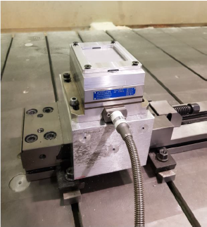
Fig. 3. Experimental measurement set up used for drilling tests
Table 1. Input parameters for experimental tests
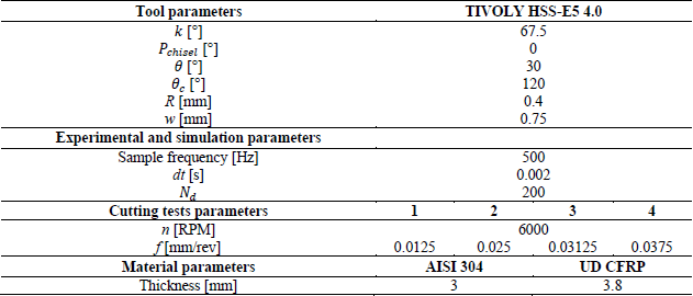
Figure 4 shows a graphical comparison between the curve obtained for the single test 1 for both AISI 304 and CFRP and the experimental measurement (filtred on Matlab thanks to a lowpass filter set at 10 Hz), and finally table 2 shows then the obtained values of the empirical parameters and the average errors in percentage for phase 2 and 4 (total immersion of the twist drill in CFRP and AISI 304 respectively).
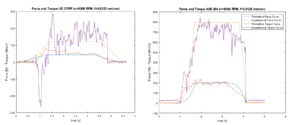
Fig. 4. Comparison between experimental measurements and the established reverse model
Table 2. Obtained parameters and results
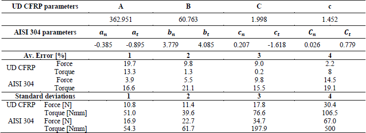
Comparison with the first experimental measurements of drilling thrust force and torque and theoretical value obtained thanks to the empirical parameters shown in table 2, average errors of 5 to 20% have been obtained. These first results confirm the reliability of the developed reverse mode despite large measurement noise shown in table 2 by the standard deviations of the experimental acquisitions for all the tests.
5 Conclusion
A new cutting force and torque model for stack metal-FRP has been developed and then experimentally validated with drilling cutting forces measurement on AISI 304 and UD CFRP. The use of Chandrasekharan and al.’s [8] and Langella and al.’s [10] empirical material parameters coupled with the developed reverse least squared minimization function allows to find easily non tool dependent parameters, giving first accurate results that will be further developed in the future (on different materials and tools). This type of algorithm allows to find reliable values and temporal evolution of thrust force and torque for stacks metal-FRP (or each of the materials specifically) on a large range of cutting parameters and thanks to a few tests, despite large measurement noise. This will then make it easier to solve problems such as premature wear of cutting tools or vibrations causing bad dimensional tolerances in drilling parts.
Acknowledgements
The autors acknowledge the Région Wallonne for funding the project under convention 1910097.
