1 Introduction
Wrinkle formation is one of the process limits of rotary draw bending. Predicting the formation of wrinkles on the inner bend of a tube is only possible approximately, since there are many influencing parameters to consider [1]. For this reason, bending processes in rotary draw bending are often based on the experience of skilled employees [2]. By means of test bends the process parameters are adjusted until the required forming is achieved. In summary, the procedure is time-consuming and cost-intensive.
In order to avoid this adjustment work, the aim of this project was to develop a fuzzy controller that recognizes wrinkling during the bending process and counteracts it by readjusting control variables. The fuzzy controller is based on fuzzy set theory and fuzzy logic, which, coupled with a set of adjustment rules, can simulate human decision making [3]. The fuzzy controller was integrated into a bending machine so that sensor data were automatically analyzed and the manipulated variables could be controlled. The fuzzy controller was validated in practical bending tests.
1. Application case
1.1. Rotary draw bending
Rotary draw bending (RDB) is preferably used for small wall thicknesses and small bending radii. With appropriate tool and machine technology, bending ratios of less than 1 can be represented.The tool assembly of the RDB is shown in Fig. 1. The tools bend die (1), clamp dies (2.1, 2.2) and pressure die (3) are necessary for the bending. Bending mandrel (4), wiper die (5) and collet (6) are used optionally.
The tube is clamped with the inner (2.1) and outer (2.2) clamp die in order to transfer the rotation from the machine to the tube. [6] The bending moment is applied by supporting the tube on the pressure die (3). The collet (6) clamps the tube at its end. The bending mandrel (4) supports the inner wall of the outer bend and thus reduces the cross-sectional deformation. To counteract wrinkling, a wiper die (5) can be used in addition to the bending mandrel.
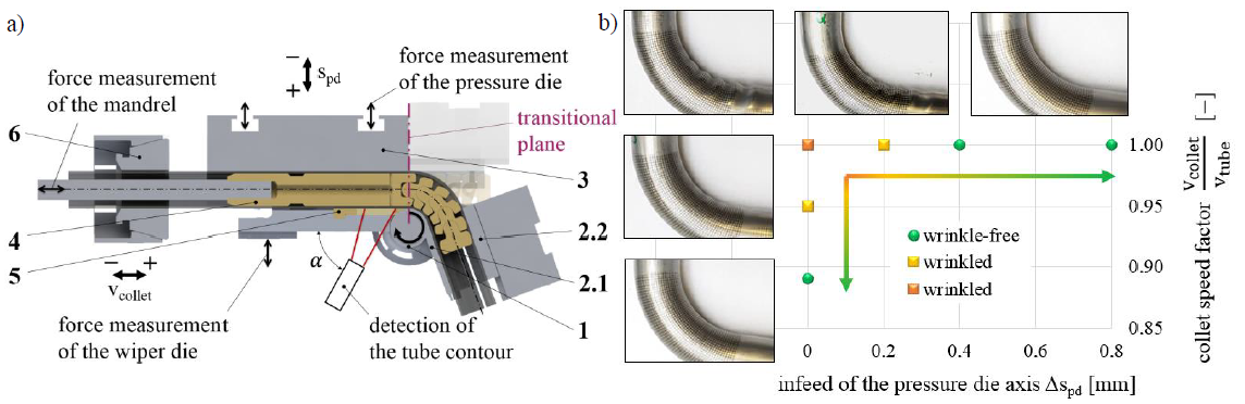
Fig. 1. (a) Tools of the rotary draw bending process [4] and (b) influence of the pressure die infeed and the collet speed on the formation of wrinkles [5].
Practical experiments show that the process parameters pressure die infeed and collet speed have a significant influence on the wrinkles [5]. The wrinkle height is reduced when the pressure die is moved towards the tube, see Fig. 1 b). In case of contact between pressure die and tube, a positive infeed causes an increase in force. If the collet speed is reduced so that tensile stresses are superimposed, this can also lead to a reduction in wrinkle height.
1.2. Fuzzy-Control
In forming technology, the change in tool forces and axis paths triggers a non-linear change in the material flow in the bending component. According to [3, 7, 10], the effort to solve a nonlinear control problem can be significantly reduced by using fuzzy logic. Fuzzy controllers are robust and can be realized with a comparatively small amount of data [8]. They are therefore cost-effective and technically feasible [9]. Fuzzy controllers were successfully applied in forming technology by [11-16].
2. Application case
The central elements of a fuzzy controller are the fuzzy sets of inputs and outputs and the control base [17]. To determine the fuzzy sets of the input values, the measurement results of the bending tests are evaluated according to [4]. A laser line sensor and a load cell on the wiper die as well as a tension-compression force sensor on the mandrel were used as input variables for wrinkle detection during the bending process. The parameters pressure die infeed and collet speed factor form the output variables.
2.1. Laser line sensor (LLT 2900-50 2D, short wave laser for precise and stable contour measurement, sampling frequency: 5 Hz) of the Micro-Epsilon measurement technology GmbH & Co. KG
From the measured data of the laser line sensor, wrinkle heights are determined, which serve as input variables for the controller. The measured wrinkle heights of the line sensor consist of the actual wrinkle height and a displacement which is caused by the mobility of the tube due to a certain clearance between the tube and the tools. The maximum value of the determined wrinkle heights defines the wrinkle height of the respective time step used for evaluation (see Fig. 2).
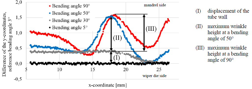 Fig. 2. Tube contour measured by laser line sensor in the area of the wiper die, see also Fig. 1 a).
To generate the fuzzy sets, the wrinkle evaluation factor ΩVDI3431 was determined for each sample of the experimental plan according to [18] and to the procedure described in [5]. The wrinkle evaluation factor is determined from the topographic height profile of the inner tube bend, whereby a comparison of the target and actual contour takes place [18]. All tests for which ΩVDI3431 = 0 are valid are assigned to the category "no wrinkles". The tests in the category "small wrinkles" have a wrinkle evaluation factor of 0 < ΩVDI3431 < 0.002. Correspondingly, the bending tests in the category "large wrinkles" have been assigned a rating of 0.002 ≤ ΩVDI3431.
2.2. Force sensor of the mandrel (tension-compression sensor U9C, accuracy class 0.2, nominal force 20 kN, sampling frequency: 5 Hz) of the Hottinger Baldwin Measurement Technology GmbH
During the tests, the longitudinal force of the mandrel was recorded over the bending angle. The derivation of the force course i.e. the course of force change has the ability to make well-founded statements about the occurrence of wrinkles. The courses of force change are subject to fluctuations. In order to reduce the fluctuations while preserving the characteristic course over time, the evaluation of every tenth data point has proven to be appropriate.
Typically, the force progression of a wrinkle-free tube has force increases and areas with an approximately constant force, as shown in Fig. 3. During the bending process, the mandrel elements are individually "taken along" by the tube, whereby the mandrel longitudinal force increases and then reaches a plateau. During the withdrawal of the mandrel 5° before the end of the bend, the longitudinal force of the mandrel decreases.
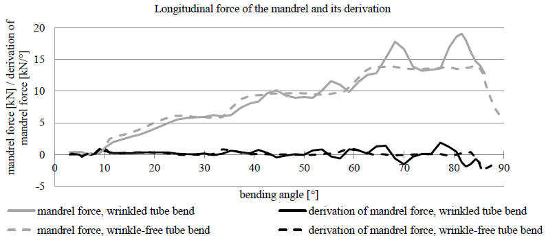 Fig. 3. Course of mandrel force and force change of a wrinkle-free and a wrinkled tube bend.
In comparison, the force progression of wrinkled tubes show a significant decrease in force even before the mandrel is pulled out. Wrinkles are pressed between the mandrel balls in the arc area and pull them apart due to the continuous bending process. At a critical longitudinal force, the wrinkles are pulled out so that the mandrel balls are suddenly relieved. This sharp drop in force is suitable for the detection of wrinkles.
2.3. Force sensor of the wiper die (load cell 301.20kN, measurement uncertainty ≤ ± 0,08%, sampling frequency: 5 Hz) of the Test GmbH
In addition to the longitudinal force of the mandrel, the transverse force of the wiper die was recorded during the bending tests. The evaluation of these data is similar to the evaluation of the longitudinal force of the mandrel, compare Fig. 4.
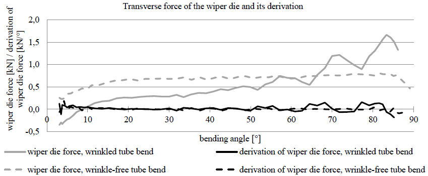 Fig. 4. Course of wiper die force and force change of a wrinkle-free and a wrinkled tube bend.
A typical force progression of a wrinkle-free bend increases at the beginning and remains at a constant level. A slight increase in force is also possible, which can be caused by different process influences. In the force progression of the tube bend with wrinkles a distinct wave form can be seen. A strong increase in force is suitable as an indicator for the detection of wrinkles.
2.4. Production rules and characteristic diagrams
The empirical values from the bending tests according to [4] serve as the foundation for the rule base which comprises 27 rules. An extract from the rule base is shown in Table 1. In order to avoid crack formation, the adjustment of the setting values with regard to wrinkling is only made as much as necessary and as little as possible.
Tabelle 1. Extract from the production rules developed on the basis of the evaluation of practical bending tests.
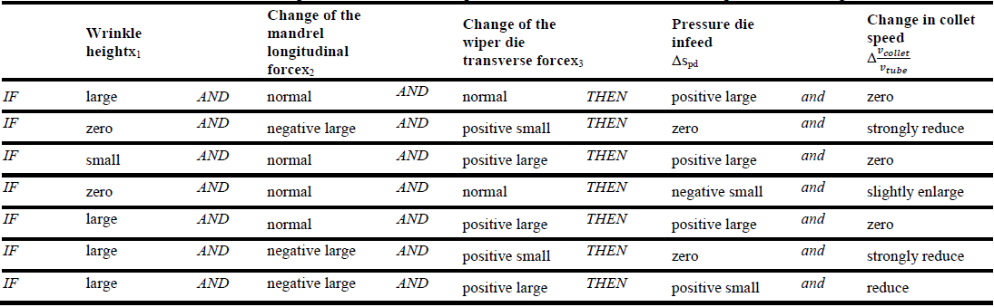
Using collet speed as a manipulated variable to prevent the occurrence of wrinkles is generally more critical for the tube with regard to crack formation if tensile forces are induced. Therefore the use of the pressure die infeed is to be preferred, see also Fig. 5 a). Secondary wrinkles, which occur in the bend area,are only detected by the longitudinal force change of the mandrel and can be eliminated mainly by reducing the collet speed factor. For this reason the collet speed factor must not be neglected. In order to consider both aspects, the collet should then act as a dominant manipulated variable against wrinkles if the mandrel detects the largest wrinkles of all inputs, see Fig. 5 b).
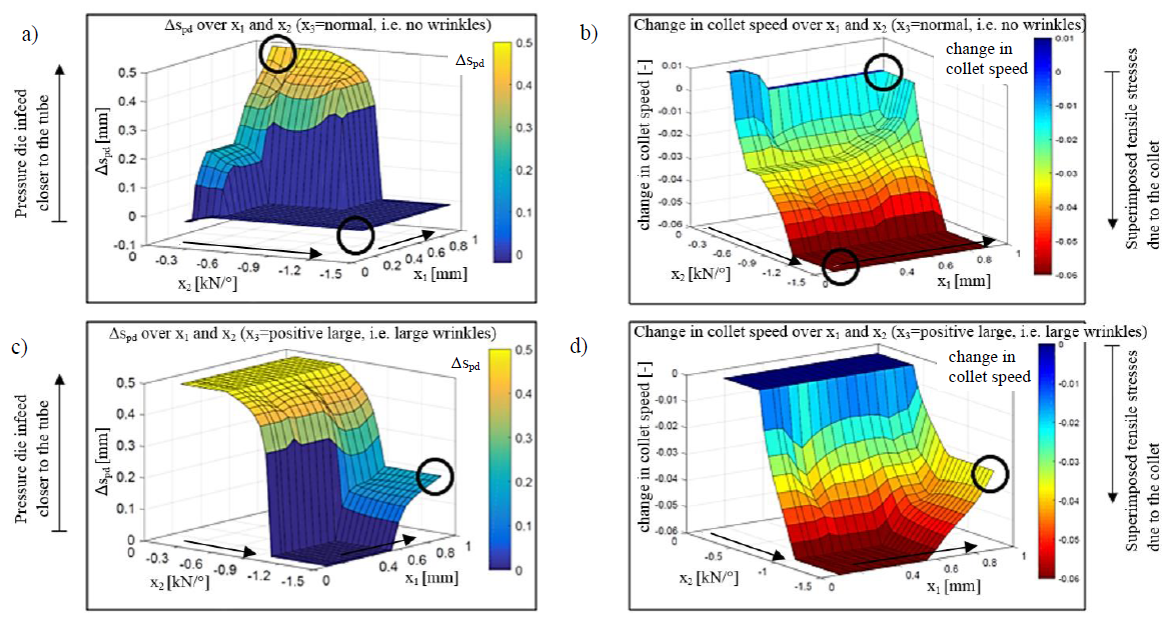
Fig. 5. Characteristic diagrams of the controller variables (Δspd and change in collet speed) according to the developed product rules, with x1 = wrinkle height measured by the laser line sensor, x2 = change in mandrel force and x3 = change in wiper die force.
(a), (b) Showing the controller values while no wrinkles are detected by the force sensor of the wiper dieand (c), (d) with detection of large wrinkles by the force sensor of the wiper die
There is a scenario where both manipulated variables are to be adjusted simultaneously as shown in Fig. 5 c) and d). This is the case when all three inputs detect large wrinkles at the same time. If pressure die and collet are adjusted to large wrinkles at the same time, the risk of cracking increases.
3. Practical testing of the fuzzy controller
3.1. Programming the controller and connection to the bending machine
The data transfer process is shown in Figure 6. First, the longitudinal force of the mandrel, the transversal force of the wiper die, and the bending angle are transferred to MATLAB R2016b using National Instruments' DIAdem 2020 software. In addition, MATLAB receives the necessary data for determining the wrinkle height from a text file of the laser line sensor. At the same time, the current position of the pressure die is detected by an inductive precision feeler and transmitted to DIAdem.
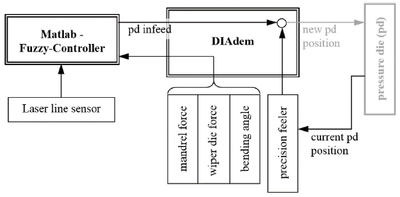 Fig. 6. Schematic diagram to illustrate the overall data transmission during practical validation tests of the fuzzy control.
As soon as the fuzzy controller has calculated a required infeed with the help of all input variables, DIAdem determines the new pressure die position to be set in connection with the current position of the pressure die. DIAdem then causes the cylinder of the pressure die axis to move to the new target position. This overall control process is run through until a termination criterion is met (e.g., reaching a specified bending angle).
3.2. Experimental procedure
Practical tests were carried out on the TN 120 bending machine from Tracto Technik GmbH. The bending angle is set to 90° for each test in order to ensure comparability. The specimens have the material X5CrNi18-10 (1.4301) with an outer diameter of 40 mm and wall thicknesses of 2 mm, 1 mm and 0.8 mm. The pressure die was moved in transverse direction a normal force of 10 kN on the tube. In the longitudinal direction, the pressure die was adjusted to move with the tube to minimize the relative speed. The wiper die was positioned conventionally. The tube end was clamped in the inner and outer clamp dies.
Since the TN 120 bending machine does not allow any intervention in the collet axis, only the manipulated variablepressure die infeed was adjusted by the controller. The output values calculated by the controller for the collet axis were recorded and evaluated. The experimental setup can be seen in Fig. 7.
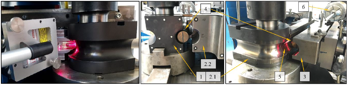
Fig. 7.Representation of the experimental setup. The numbering is the same as in Fig. 1 a).
Similar to the bending tests according to [4], the sensors described in Section 2.1 were installed. The laser line sensor is placed behind the holder of the wiper die so that the laser line strikes the tube surface in the area of the wiper die. The wiper die and its holder are provided with a slot in longitudinal direction of the tube, as shown in Fig. 7. To position the laser line close to the forming zone, the sensor is placed at an angle α > 30° to the longitudinal axis of the tube.
To validate the fuzzy control, the semi-finished product with a wall thickness of 1 mm was first bent without activating the control, see also Fig. 8. In the subsequent bends with closed-loop control, adjustments were made to the transmission frequencies, to the speed of the pressure die and to integrated force and displacement limits in order to avoid collisions and sensor damage. When three successive tube bends were bent without wrinkles (see also Fig. 9), the control was transferred to the wall thicknesses 0.8 mm and 2 mm without making any further changes to the fuzzy control except for the maximum limit of the pressure die travel spd. It was increased from 1.0 mm to 1.3 mm (see Table 2). The tube bends were scanned with the Faro Edge 2.7 M coordinate measuring arm with FARO Laser Line Probe ES and processed with the software Poly-Works 2016. The evaluation was done with the software MATLAB R2016b according to [1]. The higher the wrinkle evaluation factor, the more the actual contour of the inner arc deviates from the target contour due to the resulting wrinkles.
3.3. Results
In order to evaluate the performance of the controller in advance, first "theoretical" experiments are carried out. The input variables are sampled and the output variables are calculated by the controller, but the output variables are not implemented on the tools (controller does not intervene in the process). This allows to assess the results of the controller at different wrinkle levels. The bending of the semi-finished product with a wall thickness of 1 mm shows an increasing course of the wrinkle height, see Fig. 8 a). The course of the mandrel force change is mostly in a range that does not indicate wrinkles. The course of the force change of the wiper die detects wrinkles from a bending angle of approx. 65°. The input variables are converted by the fuzzy controller into manipulated variables for the pressure die infeed. The result is the increasing course of the pressure die infeed Δspd shown in Fig. 8 b). The manipulated variable, change of collet speed factor, remains largely unchanged, as it is dominated by the mandrel force change, which does not indicate a significant course for wrinkles.
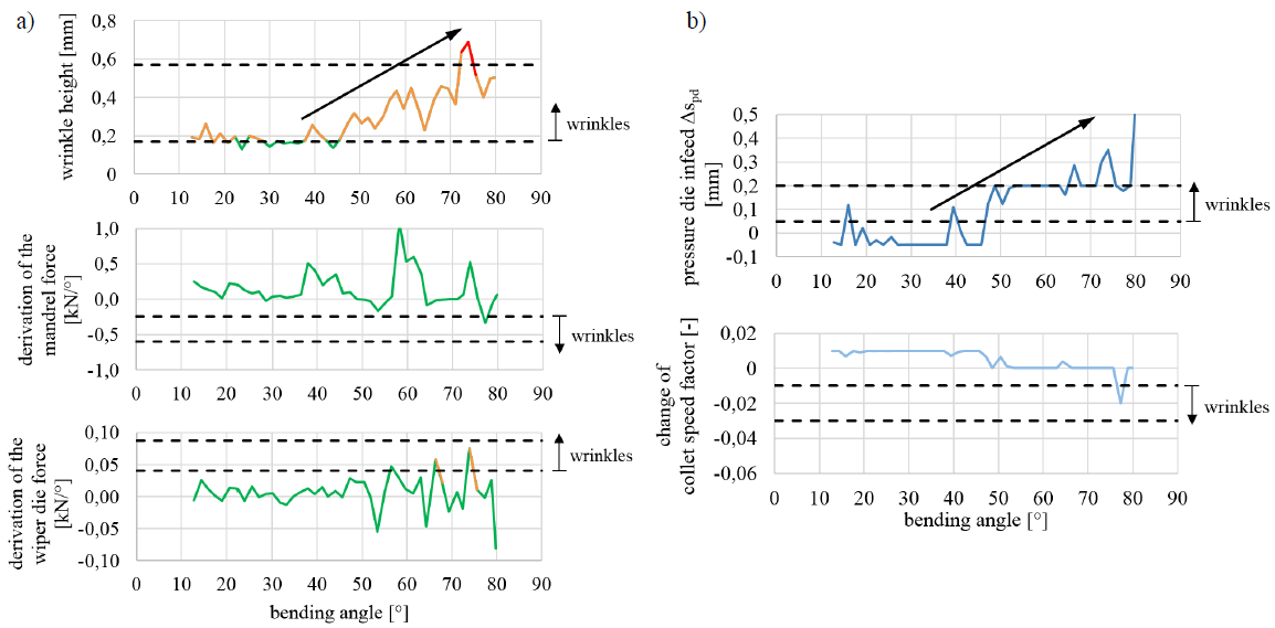
Fig. 8.Display of the course of input (a) and output (b) variables of the fuzzy controller over the course of bending anglewithout intervening in the process.
When bending the semi-finished product with a wall thickness of 1 mm with activation of the fuzzy control, the pressure die is actively fed during the bending process, see Fig. 9. The fuzzy controller determines by which amount (Δspd) the pressure die is to be moved towards the tube. Figure 9 shows that the wrinkle height always shows wrinkles for a short period of time, but then returns to the wrinkle-free area. The courses of the force changes do not indicate wrinkles. The progression of the pressure die feed matches the input value, wrinkle height. The pressure die is repeatedly advanced by a small amount, but then returns to the wrinkle-free area.
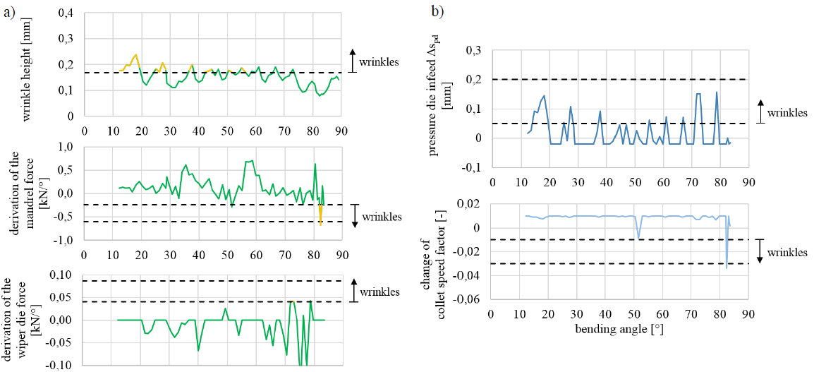
Fig. 9. Display of the course of input (a) and output (b) variables of the fuzzy controller over the course of bending anglewhile influencing the process.
In the experiment in Figure 9, the output variables are actually implemented on the tools (controller intervenes in the process). The fuzzy controller triggers an advance on the one hand but a release of the pressure die on the other if all three input variables show no wrinkles. This reduces the probability of cracks. The pressure die closes when wrinkles are detected and opens to a lesser extent when there are no wrinkles. This results in a course of the pressure die travel spd, which settles down at a position of spd = approx. 0.6 mm suitable for bending, see Figure 10. Below this value, wrinkles form. Above this value, an unnecessarily high normal force of the pressure die results. This can lead to increased tool wear, especially of wiper die and mandrel, and causes an increased risk of cracking.
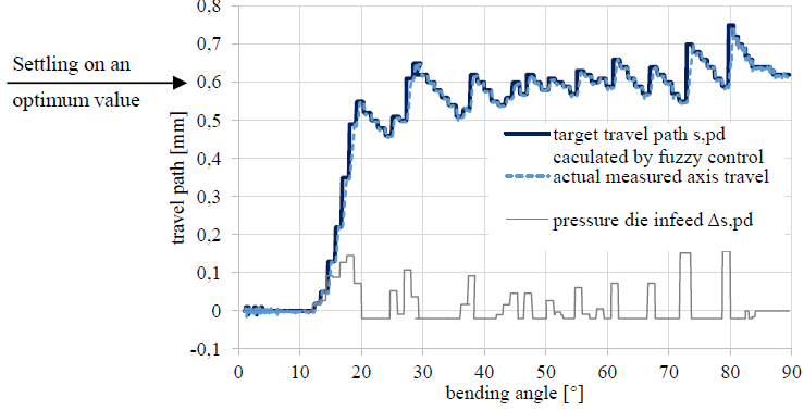 Fig. 10. Display of the set value courses of the pressure die travel and the pressure die infeed.
In summary, the most important bends of the test series are listed in Table 2. The wrinkle evaluation factor shows that wrinkle-free tube bends were bent by the automatic adjustment of the pressure die by the fuzzy controller without the operator having to make adjustments to the bending program.
Table 2. Extract from the experimental plan of the practical validation tests including wrinkle evaluation factors.
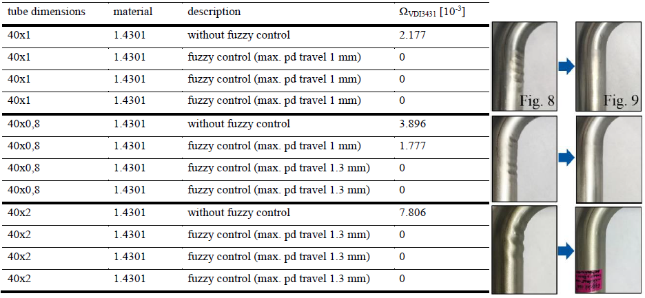
For the bends of the semi-finished product with a wall thickness of 0.8 mm, larger infeeds were required than for the wall thickness of 1 mm. The input variable, wrinkle height, dominated in this bending task similar to the 1 mm wall thickness. In the bends with a wall thickness of 2 mm, which are thick-walled tubes, the wrinkles were detected less by the laser line sensor, but mainly by the course of the normal force change of the wiper die.
4. Conclusion
In this manuscript, a fuzzy control is presented that uses the tools pressure die and collet to reduce wrinkles without the need for operator intervention in the process. The automation optimizes the manipulated variables in such a way that the formation of wrinkles is just avoided, which reduces the acting forces and thus the wear of the machine to a minimum. At the same time, these optimal conditions significantly reduce the probability of cracking.
Thin-walled tubes with an outer diameter of 40 mm and wall thicknesses of 1 mm and 0.8 mm formed wrinkles in front of the bend area. This area could be detected by the in situ measurement of the tube contour by means of a laser line sensor through a narrow slot in the wiper die. This input variable dominated for the thin-walled tubes. Wrinkle-free tubes could be produced using fuzzy controllers.
Thick-walled tubes with an outer diameter of 40 mm and a wall thickness of 2 mm formed wrinkles in the transition plane. These wrinkles were detected early by the force change of the wiper die. Wrinkles in the comparatively thick tube wall seem to have applied enough force to cause a force change at the wiper die. Wrinkle-free tube bends could be produced by means of fuzzy control.
The input variable, mandrel force change, detected wrinkles in the bend area. According to the fuzzy control, this has an influence on the collet speed as manipulated variable. For software reasons, the collet speed could not be adjusted automatically on the bending machine during the validation tests. However, the recorded target values of the collet speed were evaluated and met the expectations. A decrease in the course of the mandrel force change resulted in a reduction of the collet speed and thus in induced tensile stresses to prevent wrinkles.
