1 Introduction
Since mass personalization is a driving force within industry 4.0, conflicts arise between customer on demand diversification and mass production [1]. To solve this conflict, agile, flexible and smart production systems are required for manufacturing technologies [2,3]. Especially in forming, the development of new flexible processes or the flexibilization of well-established processes has generated a considerable research interest and brought about many special processes in bulk as well as in sheet metal forming [4].
Forming processes with geometry-specific tools (e.g. deep-drawing) are limited regarding achievable variety of part geometries with a distinct tooling. To maintain their advantage of high dimensional accuracy of produced parts, the ability to form small radii and a good process reliability on the one hand and, on the other hand, to overcome the disadvantage of inflexibility, is an ongoing research challenge. HEFTRICH et al. [5] show a method for identifying active surfaces of bending dies based on contact pressure distribution. Subsequently, the creation of simplified tools with an adjustable diameter was achieved. Moreover, multi point forming approaches arise, where the die consists of discrete actuatoric punches, which enable a great shape variation [6–9].
In contrast, forming processes with generic tools own an inherent flexibility due to their free movement of shaping tools. This could be continuously processes like three-roll-push bending [10] or incremental ones like single point incremental forming [11]. Due to the freedom to string the forming increments together, incremental processes provide an additional level of flexibility compared to continuous processes. This, however, requires a deep understanding of the forming zone and strategies to control the overlapping deformation zones [12]. Incremental methods, such as Incremental Swivel Bending (ISB), can be utilized for in-plane bending of blanks and open profiles to achieve a high degree of forming flexibility [13,14]. In ISB the bending moment is transmitted by clamping units which frictionally engage tensile or compressive loads in longitudinal direction to the semi-finished product. It is observed, that size and shape of forming zone depends on geometrical and mechanical properties of the semi-finished product, as well as on the applied clamping pressure and friction [15].
Therefore, we claim that a further flexibilization can be realized by controlling the resulting forming zone using functionally improved clamping tools to obtain a variable contact pressure distribution. Approaches to control the material flow by changing the contact normal pressure distribution are known in deep drawing with regard to the blankholder. ELEND et al. [16] show, that a pliable blank holder system with defined local stiffness leads, in comparison to a rigid blank holder, to a more homogeneous contact pressure distribution as well as to an enlargement of the safe process window and stability. In addition, several authors [17–19] report the potential of active blank holder systems, which enable in-process adjustment of local material flow due to variation of local blank holder forces. Similar, in this paper we study how modifications of the clamping tools allow us to influence the forming zone of bending processes. The active die faces are systematically segmented to allow the clamping motion to adapt to the transversal deformation over thickness of the material and therefore to preserve contact.
2 Methods
STAEVES/SENGUPTA et al. identified the deformation zone of processes with force-fitted transmission to be related to the yield sheath, which is located within the contact surface of the active clamping die faces [20,21]. For tensile stretching, the location of the yield sheath can be expressed as function of tool travel, friction and applied pressure [22]. When, in a similar setup, the clamping tools pivot about an axis, in-plane bending is provoked, cf. Fig. 1 a), where the initial clamping area is defined by the clamping length lc and the profile height h0 (see Fig. 1 b)). Under frictional engagement, an angular forming zone results reaching well within the area under the clamping tools [15], see Fig. 1 b). Due to the tooling’s rigidity, contact between material and tool releases in the forming zone and friction shear stress drops. Outside the forming zone, the bending moment Mz is transmitted at the remaining tool surface in contact.
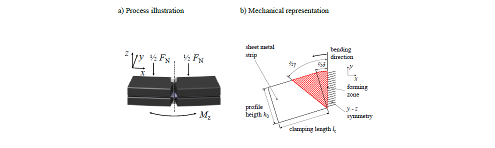
Fig. 1. In-plane bending under clamped conditions [15]. The bending moment Mz is transmitted force-fittingly at the die faces
(a) Showing the fundamental process setup and (b) the angular forming zone which opens up according to the advancing yield sheath
The idea of our approach is to segment the tooling of such a process, so that the foremost segment towards the forming zone follows the material’s transversal thinning. The segment’s contact is thus expected to be preserved keeping the forming zone narrow because shear stress hinders material from slipping. If, however, the foremost segment was introduced solely, exaggerated contact pressures would result. Thus, a ratio of clamping length lc to profile height h0 of lc / h0 ≥ 1 was postulated for continuous tools to sufficiently transmit the bending moment in a force-fitted way [23]. In contrast, a segmented tool setup could keep the contact pressures moderate due to multiple die faces, while tangential shear stress can be preserved close to the advancing forming zone. The key question is therefore, if the forming zone in a bending process can be influenced by tool segments, that can shift against each other by a vertical degree of freedom.
As a function of bending angle δ, the forming zone angle γ asymptotically converges towards a threshold, which is defined by the relation of clamping length lc to profile height h0. For square tools, the ultimate angle γult becomes 45°. The universal formulation follows

From eq. (1) it is evident that shorter tools should deliver smaller forming zones.
Similar as in the mechanical depiction of Fig. 1 b), the reference process for this study with γult = 90° on the clamping tools is illustrated in Fig. 2 a). For simulating the segmented approach of this study, first, the tool area which loses contact is removed in order to examine the influence of this surface. Triangular clamping tools result for in-plane bending, see Fig. 2 b).
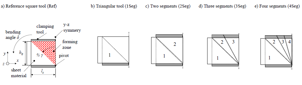
Fig. 2. Concepts of bending tool segmentation to study the influence of contact pressure distribution on the forming zone (symmetry plane illustration).
(a) Showing the in-plane bending reference of Fig. 1b, (b) the reduced tooling with a 45° cut out, (c) two 45 degree segments that are allowed to shift against each other vertically, (d) a 45° and two 22.5° segments and (e) an additional 11.25° segmentation
The concept of Fig. 2 c) features two triangular segments, which can shift against each other vertically and therefore adjust to local thinning. For the following iterations, the foremost tool segment (towards the middle of the forming zone) is successively separated into two pieces, resulting in 22.5° segments in Fig. 2 d) and an additional 11.25° separation in Fig. 2 e). The triangular clamping tool in case b) is loaded with the same clamping force FN, as the reference process because the wedge shaped cut away is expected to approximate the surface of the die face, which loses contact to the forming zone. Thus, a) and b) are expected to converge over increasing bending angle δ. The reference load FN is proportionally distributed on the segments of c) – e), which are all allowed to shift vertically. Hence, equal pressure distributions are expected to prevail in the beginning of the loaded process. As the forming zone begins to develop according to the yield sheath, the material plastically thins due to transversal strain within γ. The contact area to the die face of the foremost segment significantly shrinks and normal pressure pN increases strongly at this surface. By the stress applied rule of Coulomb, 𝑝𝑁 ∙ 𝜇 = 𝜏𝑓 , friction shear stress τf increases proportionally to pN. Material is more firmly clamped so that, concluding, the forming zone should converge towards the angle (γseg = 45°, 22.5°, 11.25°) of the foremost segment on each side of the bending tool (bearing in mind the symmetry condition).
2.1 Finite element simulation
A finite elements method (FEM) simulation from a previous study is deployed [15]. The in-plane bent strip material is discretized by 1 mm fully integrated hexaeder elements (C3D8) with seven layers over thickness. The hardening properties of the objected materials are modeled according to SWIFT’s law [24,25]. Implemented in ABAQUS 6.18, an explicit calculation method solves the numerical equations of the model.
In addition to [15], pressure dependent dry friction coefficients are implemented, which have been evaluated in [26]. Moreover, the tools are meshed by solid hexaeder elements with purely elastic behavior (E = 215 GPa). These modifications sufficiently improved the prediction performance of the numerical model of force-fitted in-plane bending.
The tool concepts shown in Fig. 2 are implemented in the FE-model. Fig. 3 shows the simulations featuring the segmented tools, in this case for the material HCT780X at a bending angle of δ = 3°.
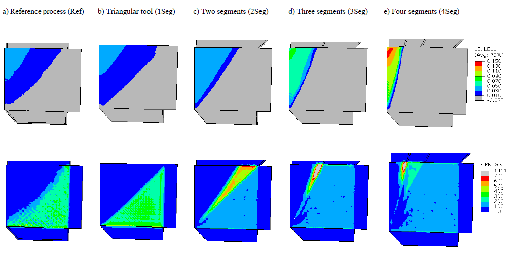
Fig. 3. Numerical simulations of in-plane bending with a symmetry setup in the middle of the forming zone (each on the left edge). For validation of the forming zone angle γ, the longitudinal strain plots are limited to εx ≥ 0.01 (upper row). The lower row shows the corresponding contact pressure distributions.
According to Fig. 2: (a) Showing the reference process, (b) with a 45° cut out, (c) two 45° segments, (d) a 45° and two 22.5° segments and (e) an additional segmentation by 11.25°
From the simulation results, the evolution of the forming zone is evaluated over the bending angle δ by means of the angle γ and its corresponding strain maximum εx,max. Two significantly different sheet metals are studied within the presented tool variation. The corresponding process setups and material parameters are presented in Table 1. The mechanical parameters for the hardening models have been evaluated by tensile tests (L80) and the friction coefficients by strip drawing experiments in a flat bed, cf. [26].
Table 1. Material and process parameters used in FEM

By these materials, strength, ductility and friction coefficients are varied significantly. The dual phase steel HCT780X (DP800) provides limited ductility but, in its zinc coated condition, higher friction coefficients. The austenitic steel FORTA H800 (based on X30MnCrN16-14) possesses advanced high strength properties and a ductile straining behavior [27]. For each material, the clamping force necessary to sufficiently bend a strip of 50 mm profile height h0 in-plane is calculated according to the analytic model of [23] which ensures firm clamping without material slipping.
2.2 Model validation
In order to validate the FE simulations, bending experiments are conducted on the ISB research tool of [13], equipped with non-segmented clamping dies (see Fig. 4). Flat strips of the materials listed in Table 1 are grid-marked electrolytically by a 2mm square pattern and, subsequently, subjected to the in-plane bending process, which is loaded by a hydraulic try-out press corresponding to the required parameters for processing each material. Subsequently to bending angles of δ = {0.75°, 1.5°, 3.0° and 6.0°}, strain maps are evaluated by optical strain measurement (OSM) from the surfaces by the AUTOGRID system of VIALUX.

Fig. 4. Practical in-plane bending experiments for validation of the numerical model
Showing the main components of the ISB research tool, which is operated in a hydraulic try-out press. Electrolytically grid-marked specimens of two diverse sheet metal materials are subjected to in-plane bending at a variation of bending angles. By optical strain measurement, strain maps are captured and evaluated with respect to maximum strain and forming zone angle. Pictured is a stainless steel sheet of the material FORTA H800 at a bending angle of 2.49°
As obtained from OSM, the longitudinal strain maximum εx,max as well as the angle of plastically deformed area γ are compared in Fig. 5 to the FE simulations and the analytical model of the in-plane bending process from [15].

Fig. 5. Validation of the numerical and analytical process models based on experiments on the ISB research tool
(a,b) Showing the forming zone and the resulting strain maxima as a function of bending angle for HCT780X and (c,d) for FORTA H800
The experiments confirm the suitability of the presented models. For the simulation, it has proven crucial to implement realistic coefficients of friction (cf. Table 1) and to use deformable bodies for the active dies. Based on the obtained correspondence from the validation, the numerical model is used to study the influence of the herein suggested tool segmentation in the remainder of our paper. In addition, the analytical model from a previous study [15] is compared. A satisfying accordance is seen by qualitative and quantitative means for the forming zone, while strain is slightly underestimated due to the assumption of a continuous strain distribution in the mathematics, even if a longitudinal transition towards the beginnings and endings of an increment is observed in experimental practice, cf. Fig. 4 bottom right image.
3 Results
From the numerical simulations of the segmented tooling, the forming zone angles as well as longitudinal strain maxima are evaluated over bending angle. Fig. 6 plots these results based on HCT780X (DP) and FORTA H800 (H).
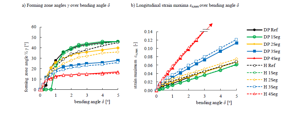
Fig. 6. Simulation based evaluation of the influence of segmented tools (1…4 Segments) on the forming zone of the bending process. For legend abbreviations see Fig. 2
(a) Showing the evolution of the forming zone angle over bending angle and (b) the corresponding longitudinal strain maxima from the simulations
While the wedge shaped cut-out (1Seg) leads to slightly lower strain values over the process, the two triangular segments (2Seg) helped to obtain a more defined and slightly smaller forming zone (cf. Fig. 3 c) while strain stays nearly identical to the reference case. If the foremost tool segment is subdivided by more iterations, 3Seg and 4Seg, significant influences on strain and the forming zone are observed. With increasing bending angle and considering the process symmetry, the forming zone converges towards the wedge angle of the first segment plus bending angle 𝛾 → 2 ∙ 𝛾𝑠𝑒𝑔 + 𝛿. On the other hand, the strain maximum of the process strongly increases with this method. Therefore, the presented tooling segmentation allows to influence the forming zone of the bending process. The evaluated results show, that the impact of material and the corresponding tribological properties cannot be neglected, but are of higher relevance with fewer but larger segments and at smaller bending angles, likely because of a more uniform contact pressure distribution.
4 Discussion
Our study investigates the influence of the forming zone of force-fitted bending by varying the contact pressure distribution within the clamping area. From a tool perspective, a finer segmentation of the clamping tools leads to higher local contact pressures, which in turn reduced the forming zone angles and increased longitudinal strain maxima. Intrinsically, a conflict of goals results. If the aim is to keep the forming zone as small as possible in order to achieve closely spaced forming increments and possibly small bending radii, the forming capacity of the material might be exceeded. To overcome this problem, strategies are crucial for the arrangement of forming increments by simultaneously accounting on material failure limit, maybe by adaptively changing increments during the process sequence. By influencing the location and extension of the forming zone, our approach opens up perspectives to control the material flow of the process, which potentially enlarges the safe process window and stability. Moreover, a higher process flexibilization is achieved with regarding feasible part geometries if the forming zone becomes controllable.
The presented method allows to vary the contact pressure distribution by introducing concepts for a clamping tool with a vertically shiftable segmentation. The required clamping force per segment is determined by press load required for force-fitted bending divided by each respective segment area. According to [17], we introduce a passive adaptive system, in which the contact pressure results from the tool setup with respect to segmentation and press load. Up to now, no in-process adjustment of the forming zone is possible. To close this gap, active systems need to be developed in future work. For this purpose, our research will focus on both, creating suitable tool concepts for the creation of active and passive adjustable contact pressure distribution as well as a more universal understanding of relationship between pressure distribution and forming zone. Beyond fixed segmentations, we assume further potential to control the forming zone with a freely adjustable contact pressure gradient. Besides a flexible tool design and actuators for adjusting tool surfaces, the integration of sensors, ideally sensoric layers, are crucial to measure the contact pressure distribution in-situ. These topics will be explored within the Centre of Smart Production Design Siegen (SMAPS).
5 Conclusions
In order to meet the increasing demand for mass personalization in manufacturing technology, equally flexible forming processes are required [2]. Incremental Swivel Bending (ISB) is an incremental process for in-plane bending of blanks and profiles, which aims for this demand. Due to the frictional transmission of the bending moment, the process is independent of the tool geometry, which enables the processing of a great variety of semi-finished products and the production of different bending geometries with one tool set. However, the resulting forming zone depends on the properties of the material as well as on the applied clamping pressure and friction.
In order to tap further manufacturing flexibility potential, the present work investigates, whether a variation of contact pressure distribution at the clamping tool influences the resulting forming zone and strain gradient of an in-plane bending process such as ISB. To this end, we validated a finite element process model and subsequently segmented the clamping tool in increasingly finer subdivision. The segments are allowed to freely adjust in the direction of applied clamping force to follow the transversal material flow. It has been observed, that a finer segmentation lead to a coarser contact pressure gradient, which strongly increases towards the edge of the forming zone. Consequently, a finer segmentation causes a smaller forming zone angle by hindering the material from being stretched out of the clamping and higher strain maxima are observed.
With regard to modifications of the active clamping die faces, the present work outlines the potential to control the forming zone in clamped bending processes such as ISB, which in turn offers a higher manufacturing flexibility. This study is the first step towards both, enhancing fundamental understanding of the relationship between forming zone and contact pressure distribution as well as a process development, including new tool concepts, integration of sensors and actuators and closed-loop controls.
