1 Introduction
Due to the tightening in green-house-gas emission regulations, the demand for light-weight parts especially in automotive industry has been continuously rising in the last two decades [1]. Particularly in sheet metal forming applications, two different approaches have been developed to reduce the thickness and hence weight of parts without compromising the safety and crashworthiness [2]. First one is to replace conventional materials with their higher strength counterparts, either advanced-high strength steels (AHSS) or ultra-high strength steels (UHSS) and so to be able to carry the same loads using less material. Second strategy is the application of press hardening process where austenitized steels are hot formed and quenched in the same die system. That way, martensitic microstructure and hence strengths exceeding 1500 MPa can be reached in the produced parts without ductility problems [3]. Nevertheless, press hardening process is significantly more energy demanding than conventional stamping or deep drawing processes. Therefore, in the design and production of comparatively simple parts such as bumper reinforcements, door beams or seat tracks, where high ductility is not necessary, cold forming became the preferred forming technology. However, even in the manufacturing of simple geometries, multiple forming processes may be necessary.
Roll forming is a process where flat sheet metal strips are bent to a product using consecutively arranged roll sets [4]. Due to its high efficiency, this process is preferred in the manufacturing of open and closed profile type geometries. On the other hand, stretch forming is a process where flat sheet panels are formed under tensile stresses using a punch and axial gripper system [5]. It is majorly used in automotive, aerospace and shipbuilding industry to manufacture large curved parts. During tangential stretch forming, flat sheets are pre-stressed up to their yielding point and afterwards, a uniform deformation is generated on the material in tangential direction using a punch [6].
In the design of bumper reinforcements, in order to increase the stiffness, usually an open profile geometry is used. Moreover, to increase the pedestrian safety, ends of these parts are curved. Such a geometry can be efficiently manufactured using roll forming and stretch forming combination. However, to author’s best knowledge, such a combination hasn’t been investigated. Therefore, the paper at hand aims at investigating and validating the stretch forming process of an open profile using FEA and experiments.
2 Process and Material
The investigated bumper reinforcement geometry is shown in Fig. 1. The total length, width and depth of the profile are 585 mm, 142 mm and 44 mm, respectively. Thickness of the sheet metal used is 1.5 mm. The part is divided into two regions over its length; a comparatively flat middle section and curved outer section. In its cross-section, a modified hat shape is used with a hump around the middle to increase the stiffness of the part.
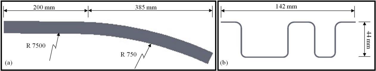
Fig. 1. Bumper reinforcement geometry.
(a) Side view, (b) front view
In conventional stretch forming, in order to reach a uniform strain distribution in the finished parts, sheet metals are first pre-stretched and formed afterwards. Thus, it is bending with superimposed tensile stresses where induced strain over the thickness is assumed to be constant [5]. However, tool design is made differently in stretch forming of profiles. It is intended not to form the inner (lower) section of the profile plastically. Moreover, induced plastic strain on the outer (upper) section should be below fracture level of the material used. It can be calculated using following equation (1).

where d is the depth and ri is the inner radius of the profile. Using Equation 1, outer strains in the middle and curved sections f the current profile are calculated as 0.58% and 5.8%, respectively. Fracture of the material used should be higher to be able to generate sound parts.
The die system to realize stretch forming consists of three different parts (Fig. 2). First one is the stationary fixed die in the middle section of the profile. This die supports the profile only from outside and stretches till the middle of the curved section of the part. Second part is the lower stretching clamp which supports the profile from the outside. Lower stretching clamp matches the curved geometry of the final profile. Third part of the die system is the upper stretching clamp. This clamp is open at the beginning of the process. During forming, a clamping force is applied using upper clamp and together with lower stretching clamp, these two parts rotate around center of rotation of the system and thus generate the stretching movement. For the investigated profile, the rotation angle was 26.5°.
The profile geometry shown in Fig 1. (b) is produced using cold roll forming process. The production required 28 roll forming steps. Moreover, after the forming, the geometry profile is fixed in 3 additional calibration stands prior to stretch forming.
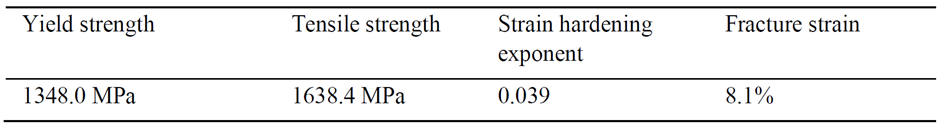
The material used in the study is MS1500 ultra-high strength steel with a predominantly martensitic microstructure. Mechanical properties of the material is characterized using tensile tests according to ISO 6892-1 standard and the results are summarized in Table 1.
Table 1. Mechanical properties of MS1500 steel.
3 Finite Element Analysis and Experiments
In order to investigate the feasibility of the process and validate tool designs, stretch forming of the open profile is investigated using finite element (FE) analysis. The FE model is generated with the software package MSC.Marc 2015 (Fig. 2). Due to the symmetry of the profile, only half of the workpiece geometry is modeled. Accordingly, symmetry plane is fixed in x direction. Workpiece geometry is modeled using 35720 four-noded isoparametric planar elements (Element 11). Thickness of the profile is defined as a property in these shell type elements. Tool geometries are generated as rigid surfaces and a Coulomb friction coefficient of 0.1 is defined between tool and workpiece. Due to the low strain rates during forming, quasi static state assumption is made.

Fig. 2. Finite element simulation model of the stretch forming process.
The mechanical behavior of the investigated steels has been described with Swift’s isotropic hardening law:

Stretch forming process is modeled assuming a production time of 2.4 second. That time is divided into three different load cases. In all of the load cases, middle die in the system is fixed and doesn’t move. In the first load case, upper stretching clamp is pressed on the workpiece with a force of 80 kN while other forming clamp is stationary. The clamping force is defined using a table which gradually increases in the first load case from zero to 80 kN within 0.2 seconds. That load case is divided into 20 equal time increments.
Forming is accomplished in the second load case which is modeled in 2.0 seconds and divided into 100 equal time increments. Clamping force is kept constant at 80 kN during forming and it follows the rotation movement of upper clamp. This force assured that profile didn’t slip inside the clamps. As a result, the intended stretching is realized. In addition to the applied force, upper and lower stretching clamps are rotated around the center of rotation which is marked with a red dot in Fig. 2. Both clamps are rotated by 26.5°. In the design of the process, 6.5° springback is foreseen. That release in the profile is modeled in the last load case, where the force from upper stretching clamp is removed first. Afterwards, while all dies were stationary, upper clamp is rotated back by 6.5° to release the profile. This release is realized in 0.2 seconds and the load case is divided into 50 equal time increments.
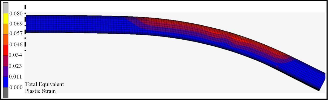
Fig. 3. Total equivalent plastic strain distribution in the stretch formed profile.
Total equivalent plastic strain distribution in the stretch formed is given in Fig. 3. First of all, the calculated geometry shows that bent profile can be formed without any wrinkle formation with the designed dies. Moreover, there aren’t any plastic strains in the inner (lower) section of the profile.
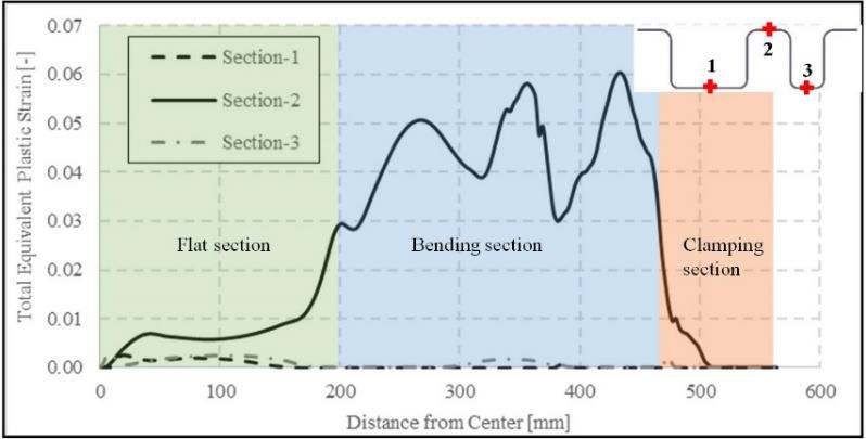
Fig. 4. Total equivalent plastic strain distribution along the profile length in three different sections.
Total equivalent plastic strain distributions in stretch formed profile along length direction is shown in Fig. 4 on three different sections. First and third sections are at the bottom, second section is on top of the profile. It is clear that bottom section of the profile haven’t undergone plastic deformation. A small amount of deformation is observed only in the flat section of the profile. Nevertheless, the strain values are below 0.003. On the other hand, a comparatively higher plastic deformation is observed in the second section which lies on top of the profile. Here, strains in flat middle and clamping sections are low. As intended, the majority of the deformation is concentrated in the bending section. However, three different peeks is observed in the bending region. First and second peeks from the left correspond to the ends of fixed die and lower stretching clamp, respectively. The third peek is seen at the beginning of the upper stretching clamp which incorporates a small bending section. These strain concentrations are actually caused by the relaxations after the end of the fixed die and clamps where the profile is not supported by the die system and can move freely. An important aspect is that the maximum strain in the numerical analysis is fairly close to the analytically calculated value of 5.8%.
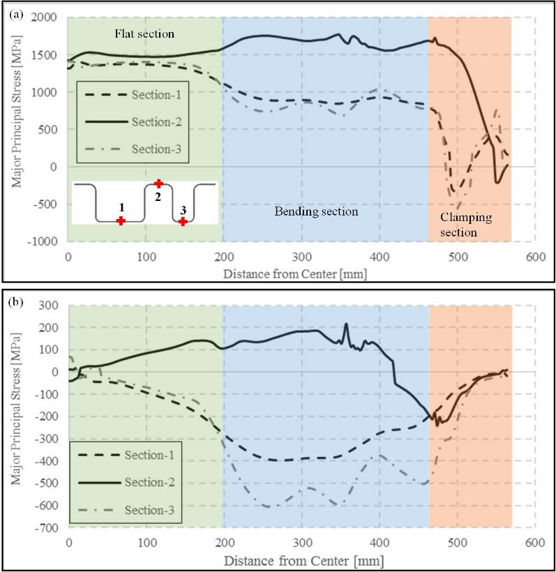
Fig. 5. Stress distribution along the profile length in three different sections.
(a) At the end of the forming, (b) residual stresses after die opening
Major principal stress distribution along the profile length which coincides with the stretching direction is shown in Fig. 5. At the end of the forming, stress distribution in different flat sections is fairly similar and slightly above yield strength. This explains small deformation in all three different investigation paths of the profile. In the bending section, stresses are significantly higher at the investigation path 2 compared to the bottom regions. This is where the majority of the stretching is realized. In the clamping section, stresses drop to zero along all sections. After the clamps are opened, a significant stress relaxation is observed throughout the profile (Fig. 5b). In the stretched upper section, the majority of the residual stresses are still in tension region. On the other hand, on the bottom of the profile, stress relaxation on the strain hardened upper side compresses the profile and causes compressive residual stresses. Moreover, the compressive stresses are higher along the narrower section 3 of the profile compared to the wider section 1. The difference is related to the stiffness of the profile in different sections. Since the third section is narrower, bending due to stress relaxation requires higher forces and hence, higher compressive stresses are trapped. On the other hand, bending of the wider first section is easier. As a result, lower compressive stresses are observed in that region.
In the light of the FE analysis, an initial tool system is manufactured and first test samples manufactured. A stretch formed profile is shown in Fig. 6 as an example. There were no cracks on the produced part.
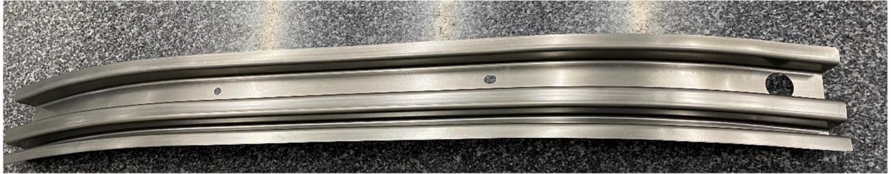
Fig. 6. Manufactured stretched formed profile.
In order to validate the FE analysis, the lower contour of the manufactured profile is compared with the FE results. The comparison is demonstrated in Fig. 7.
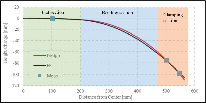
Fig. 7. Contour of the lower profile edge.
Red and black lines in Fig. 7 represent the design of the profile and FE results, respectively. Squared dots show manufactured profile where measurements are made using a coordinate-measuring machine (CMM). It is seen that FE simulation can build the desired profile geometry accurately. The maximum deviation between the design and simulation is 3.4 mm and it is located in the middle of the bending section. In the flat and clamping sections, difference between them are lower. Moreover, measurements in the manufactured part are closer to the design than FE analysis. In the three points, maximum deviation was at the end section of the profile. Its value was 0.98 mm.

Fig. 8. End cross-section of the profile.
(a) Manufactured, (b) numerically simulated
Finally, end cross-section of the manufactured and numerically simulated profile are compared in Fig. 8. Due to the residual stresses generated during stretching, a warping is observed in the end of the manufactured profiles. The stretching of the upper part of the profile generates an elongation. The elastic portion of that deformation is relaxed during springback. As result, whole profile is compressed. However, since the upper section was already stretched and was under excessive tensile stresses, residual values still stay in tension region after unloading (Fig. 5). On the other hand, tensile stresses in the lower parts of the profile are relatively lower. Therefore, a sign change in the stresses occurred during unloading. As a consequence, a deterioration is observed in the profile end. Due to the comparatively low rigidity of the wider section, warping in that region was bigger. Therefore, lower compressive residual stresses are observed in the wide section compared to narrow one. A higher compressive residual stress is trapped in the narrow section of the profile (Fig 5.b). Same warping is observed also in FE simulations. However, predicted angular deviation from the design geometry is slightly higher than experimental part. It is related to the low rigidity of the two-dimensional planar elements.
4 Conclusions
Stretch forming process of an open profile made of UHSS MS1500 steel is investigated using finite element simulation and experiments. The process and its design strategy is different compared to conventional stretch forming applied to flat products.
Finite element model of open profile stretch forming process is built using two-dimensional planar elements as workpiece and rigid surfaces as forming dies. In the analyses, quasi static state assumptions is made and implicit solver of commercial software MSC.Marc 2016 is used.
FE simulations proved the feasibility of the process. FE results are validated using stretch forming experiments. It is seen that the FE method can represent part geometry accurately. Profile of the part could be modeled with deviations lower than 3.4 mm on a part length of 1170 mm. Moreover, warping on the open end of the manufactured profile can also be modeled using FE analysis. Those deformations are caused by the residual stresses trapped in the formed part after unloading.
This study at hand showed that FE simulations can be used in the design and optimization phases of stretch forming process of open profiles. FE method is capable of accurately depicting the part geometry. Moreover, residual stress distributions can be used to evaluate deformations in the profile geometry.
