1. Introduction
Several researches demonstrate the effectiveness of auxiliary systems to increase product accuracy and process robustness in sheet metal forming operations. Hydraulic shock dampers are used in sheet blanking to reduce process noise and to avoid reverse load occurrence [1], [2]. Nitrogen gas springs are implemented to achieve a better control of blankholder force during deep drawing [3] and to create an “in-die” cushion [4]. However, these systems have intrinsic limitations, e.g. hydraulic dampers present short stroke and the nitrogen gas springs maximum force is available only at the end of the stroke. As result, the implementation of these auxiliary systems is limited to certain types of processes.
In the last decades, Magneto-Rheological (MR) fluids became attractive and their properties have been investigated in many researches. The essential feature of MR fluids is their ability to change their behavior from a Newtonian fluid, with linear viscosity, to a semi-solid having a controllable yield strength in milliseconds when exposed to a magnetic field. MR devices are utilized in valve mode, shear mode and squeeze mode [5] and are applied in many areas, such as civil engineering, safety engineering, transportation, life science and more [6]. However, MR fluid-based systems are also utilized in manufacturing engineering. Ghiotti et al. [7], [8] applied them in blanking to reduce the reverse load effect and to improve the product quality. Yun et al. [9] adjust the blank holder force during deep drawing thanks to the integrations of a MR damper. Kishore et al. [10] realize a MR damper to reduce tool vibrations during hard turning process.
The aim of this works is the numerical validation of the design of a MR actuator for sheet metal stamping operations capable to overcome the limitations of hydraulic dampers and nitrogen gas springs. The prototype, working in valve mode, presents a novel electromagnetic circuit configuration with an inner annular element. This solution allows obtaining a compact design suitable to be integrated in stamping tools or as blank holder actuator, without any reduction in the total available force compared to other commercial solutions. Design activities are supported with FE software to study the electromagnetic interaction between MR fluid and actuator parts and to estimate the magnetic forces. A physical prototype is manufactured according to the FE results and tested in laboratory equipment. Experimental and numerical results in terms of magnetic force are compared for different values of input current and testing velocity. Finally, the main conclusions are reported.
2. MR fluid modeling and selection
The MR fluids are suspension of micro sized iron particles in a liquid carrier, such as mineral oil. When exposed to a magnetic field, the ferrous particles form magnetic dipoles that align themselves along the lines of magnetic flux. Therefore, the yield shear stress, to be exceeded to activate the fluid flow, increases with the amplitude of the external magnetic fields.
MR fluid can be modelled by nonlinear Bingham plastic model:

where 𝜏 is the shear stress, γ̇ is the shear rate, 𝜏0(H) is the yield shear stress changing in respect of magnetic field amplitude H and η the viscosity of MR fluid independent on magnetic field [11]. According to the Bingham model, the MR fluid behaves like a rigid below the yield shear stress 𝜏0. In this condition, the MR fluid forms a plug flow region called pre-yield region. The local shear stress exceeds the yield shear stress in the post-yield region and the MR fluid acts like a viscous fluid. The pre-yield and post yield regions with the MR fluid velocity profile are shown in Fig. 1a. The width of the pre-yield region is represented by the symbol y0 and its value depends on the MR fluid flow conditions [12]. The pressure drop develops in a MR device depends on the geometry and electromagnetic circuit pole configuration. The pressure drop in a device operating in valve mode (Fig. 1b) is commonly assumed as the sum of a viscous component Δ𝑃η and a magnetic component Δ𝑃τ. This last component can be expressed as:

where, h is the gap width and L the active pole length. The dimensionless parameter c ranges from 2 to 3 in respect of the pressure components ratio Δ𝑃τ/Δ𝑃η [13]. The magnetic force component Fτ is calculated from eq. (3) considering the cross-sectional area Ap of the piston:

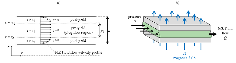
Fig 1. a) MR fluid velocity profile across the annular duct; b) valve mode
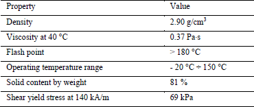
The selected MR fluid is the ARUS AMT-SMARTEC+ and its properties are presented in Table 1. According to the manufactured specifications, the MR fluid presents a response time lower than few milliseconds, the change in shear yield stress due to the external magnetic field H is totally reversible and temperature independent and yield shear stress can achieve a value of 69 kPa when exposed to a magnetic field H amplitude of 140 kA/m.
Table. 1. Properties of ARUS AMT-SMARTEC+
3. MR actuator
The geometry of the designed prototype is presented in Fig. 2a. Unlike the conventional MR damper design, the winding coils are realized along the inner annular static element. This solution permits to increase both pole length L and the winding coils number, with the aim to increase the total force available at the MR actuator maintaining compact the overall dimensions. Two independent chambers for high-pressure gas are obtained in the cylinder head and inside the rod: the former to pressurize the MR fluid volume and reduce any delay in the response, the latter to allow the piston return to the top dead center after the descending stroke.
Due to the piston stroke, the MR fluid is forced to flow through the annular gap as shown in Fig 2b. Along the gap, the MR fluid is activated by the magnetic flux generated by the coils. A layer of dielectric epoxy resin is deposited over each winding coils as protection by the MR fluid. The controllability of the MR actuator is provided by varying the excitation current of the coils.
The prototype elements are manufactured in AISI 1040 steel, with exception of the compensator made of bronze-aluminum alloy. To increase material magnetic permeability and magnetic saturation value, AISI 1040 steel is subjected to heat treatment of complete annealing. The B-H (magnetic induction field amplitude B – magnetic field amplitude H) curve of the annealed AISI 1040 can be seen in Fig. 1c. To avoid permanent material magnetization, the value of 1.8 T is assumed as maximum permitted magnetic induction field amplitude exerted on the material. After this value, the curve presents a plateau, which represents the incipient material magnetic saturation. Design data of MR device and parameters of electromagnetic circuit are reported in Table 2.
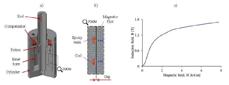
Fig. 2. a) MR prototype geometry and components; b) Electromagnetic circuit schematization; c) AISI 1040 nominal B-H curve
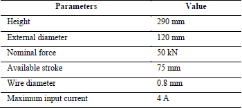
Table 2. Design parameters of MR actuator
4. Calculation of magnetic field and induction field using finite element method
The FE model of the designed prototype is developed with Ansys MAXWELL software to obtain the magnetic field amplitude H of the activated MR fluid and the induction field B distribution along the cylinder, the inner static element and the MR fluid. The values of magnetic field amplitude H are then used to calculate the corresponding shear yield stress 𝜏0(𝐻) and to obtain the magnetic force component 𝐹𝜏 by means of eq. (4). The maximum values of induction field B are compared to the B-H curve of AISI 1040 (Fig. 1c) to avoid the permanent magnetic saturation in the material.
Before analyzing the complete electromagnetic circuit, composed of gap, external cylinder and inner bore with four winding coils, a simple model with one winding coil is developed. The purpose of this preliminary study is to select the single module geometry configuration that maximizes the magnetic field H applied on the MR fluid without exceed the induction field B maximum values of 1.8 T.
Once the optimized single module geometry was selected, the electromagnetic circuit of the MR actuator is realized providing four modules on the inner bore.
Single module and complete actuator geometry are developed using 2D axisymmetric model. External air boundary is used to insulated both models. AISI 1040 B-H curve, reported in Fig. 2c, is implemented for rod, piston, inner bore and cylinder. General bronze material and copper material properties are used to model respectively the compensator and the multi-turn winding coils.
Each simulation is run with parametric sweep, varying the input current from 0 A to 4 A, with step of 1 A. Hence, magnetic fields H with different amplitudes are generated.
MR fluid characteristic curves provided by the manufacturer are implemented in the FE model to reproduce the magnetic properties of MR fluid domain. B-H curve of MR fluid is reported in Fig 3a, while the linkage between the applied magnetic field amplitude H and the change in MR fluid yield shear stress 𝜏0 is given by the curve reported in Fig. 3b.
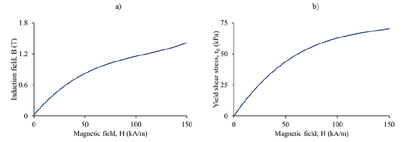
Fig. 3. ARUS AMT-SMARTEC+ characteristic curves
a) B-H curve; b) 𝜏0-H curve
4.1 Single module geometry optimization
The geometry of the single module is characterized by the module height Hm, the active pole length L, and the coil length Lc. A parametric magneto-static FE analysis is developed in ANSYS Maxwell environment. During the different steps, the average value of magnetic field H and the maximum value of induction field B for an input current of 4 A are analyzed.
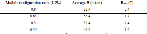
The single module geometry varies according to four values of L/Hm ratio. The height of the module Hm is fixed because it is constrained by the designed stroke of MR actuator (Table 2). The four modules geometry configurations are shown in Fig. 4 and the average values of H and the maximum values of B are presented in Table 3.
The module with a ratio L/Hm of 0.65 presents the higher average values of H and the maximum induction field values does not exceed the magnetic saturation. Therefore, this module configuration is selected to realize the four modules inner bore for the MR actuator.
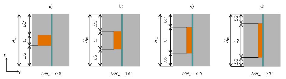
Fig 4. Single module geometry and dimensional parameters
a) L/Hm = 0.8; b) L/Hm = 0.65; c) L/Hm = 0.5: d) L/Hm =0.35
Table 3. Maximum values of Magnetic field H amplitude and Induction field B amplitude for different module geometry configurations
4.2 Four modules actuator model
Fig. 5a shows the geometry implemented in ANSYS Maxwell FE software. As for the parametric analysis on the single module case, the geometry is built as 2D model. This approximation is allowed thanks to both axisymmetric geometry of MR actuator and electromagnetic phenomena arising between MR fluid and circuit.
The Ansys Maxwell 2D software uses triangular elements to build the model mesh, as shown in Fig. 5b. The general mesh size is 15 mm, which became smaller in correspondence with the annular gap and the inner bore, in order to study more accurately the distribution of magnetic field H and induction field B in these regions. Across the inner bore, the average element size is about 2 mm, while, in the annular gap, the element size is in the order of few tenths of millimeter.
Fig. 5c presents the distribution of induction field B along the material for a maximum input current of 4 A. The inner bore presents the maximum values of induction field B. However, this value is lower than 1.8 T. Therefore, the risk of magnetic saturation of this component is avoided. Fig. 5d shows the distribution of magnetic field values along the activated MR fluid in the narrow gap for an input current of 4 A. The average value of magnetic field is considered to obtain the MR fluid shear yield stress 𝜏0(𝐻). Then, 𝜏0(𝐻) is used to calculate the value of magnetic force, by means of eq. (4).
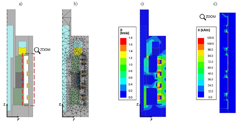
Fig. 5. a) 2D model of MR prototype; b) mesh view; c) Induction field B amplitude along the MR prototype model; d) Magnetic field H amplitude along the gap
5. Experimental tests
The manufactured prototype is tested on a laboratory equipment 50 kN MTSTM dynamometer. Experimental tests are conducted with two values of descending piston speed v0 (50 mm/s and 100 mm/s) and a stroke of 50 mm. Four input current values ranging from 1 A to 4 A are used to validate the performances of the MR actuator. The two inner chambers of prototype head and inner rod are filled with pressurized nitrogen gas at initial pressure of 35 bar.
Fig 6 presents the experimental results in terms of total load of the MR actuator during the performed stroke. The 0 A curves correspond to the viscous force components of the MR actuator. The variation of the curves from 3 A to 4 A is limited due to the modest increase in MR fluid yield shear stress. This can be caused by the local magnetic saturation of MR fluid and, consequently, the yield shear stress does not increase further. The force growth to the maximum values is not instantaneous. This fact can disagree with the instantaneous change in yield shear stress of MR fluid due to the external magnetic field H. Nevertheless, the first part of the stroke is required to compress the liquid carrier part of MR fluid. After that, the MR actuator load remains almost constant, as shown by the experimental curves.
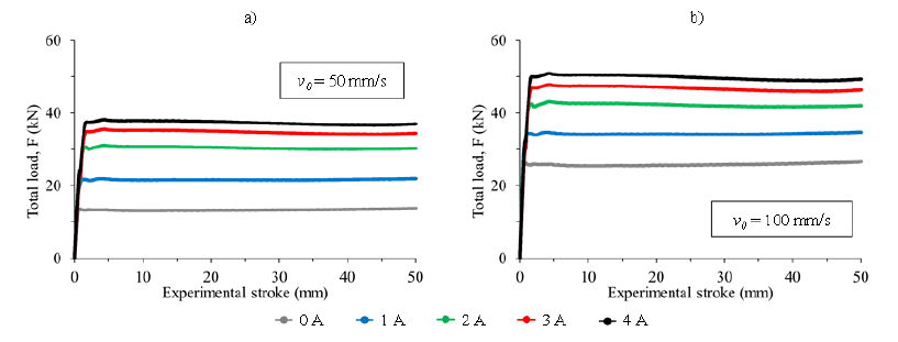
Fig. 6. Experimental total force-stroke curve
a) piston descending velocity v0 = 50 mm/s; b) piston descending velocity v0 = 100 mm/s
6. Magnetic Force comparison
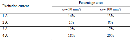
The experimental and numerical values of magnetic force are compared for each values of input current and experimental velocity, as shown in Fig 7. In both diagrams the numerical values behave similarly. For an input current of 1 A the numerical values are slightly lower than the experimental ones. This difference becomes smaller with an input current of 2 A. For input current values of 3 A and 4 A, the difference between numerical and experimental magnetic forces arises, and the numerical model overestimates the experimental values. The percentage errors are collected in Table 4. For 1 A the percentage error is similar in both velocity case, while, for 2 A the percentage error falls below the 10%. In the case of piston speed of 50 mm/s, the percentage error assumes the absolute lower value of 1%. The percentage error increases for the excitation current values of 3 A and 4 A, without exceeding the maximum value of 20%.
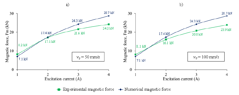
Fig. 7. Magnetic force comparison
a) piston descending velocity v0 = 50 mm/s; b) piston descending velocity v0 = 100 mm/s
Table 4. Magnetic force percentage error
7. Conclusions
The paper presents the numerical design of a new MR actuator for sheet metal stamping operations, as alternative to the conventional auxiliary systems, i.e. hydraulic dampers and nitrogen gas springs. The design activities are supported with FE tools, to select the optimized module geometry and to obtain the magnetic field H distributions along the narrow gap. A physical prototype is manufactured according to the numerical simulation results and tested in laboratory environment. Afterwards, numerical and experimental values of magnetic force are compared for different values of input currents and experimental velocity of the piston.
The main conclusions can be summarized as follows:
-
the magnetic force obtained from the FE numerical model and analytical formulation presents an error below 10% with respect to the experimental magnetic force for an excitation current value of 2 A
-
for an excitation current of 1 A, the experimental magnetic force exceeds the numerical values with an error of 14% in the case of piston velocity of 50 mm/s and 13% with piston velocity value of 100 mm/s
-
for excitation current values of 3 A and 4 A, the numerical magnetic forces exceed the experimental ones and the maximum percentage errors of 18% and 20% appear in the case of 4 A and piston velocity values of 50 mm/s and 100 mm/s respectively.
