1 Introduction
The term Additive Manufacturing (AM) describes an innovative technology capable to manufacture parts layer upon layer as opposed to subtractive and formative manufacturing technologies [1]. In the early stages, it was mainly used for prototyping, while today it is widely used for manufacturing functional parts for several application fields, such as aerospace [2], automotive[3], energy [4] and medical [5]. Compared to traditional technologies, the AM allows to have wide freedom of component design [6] and speed up of product development process. It is a resource-efficient process that minimizes material waste, adding material only where it is necessary, for obtaining lighter components [7]. In addition to the AM technologies for polymers, new processes capable of printing components by adding metal powders layer by layers were developed, providing high-resolution hollow parts with physical and mechanical properties comparable to those obtained by traditional technologies [8,9]. Metal AM processes spend a lot of energy for sintering the metal powders generating a high cost of equipment and great expenditure of time. These characteristics suggest the need to introduce an affordable metal AM fabrication method in terms of investments, processes, activities and maintenance. In this way, it would be possible to expand the applications to no high added value products. A possible answer to this need could be found in the arrangement of Fused Deposition Modelling (FDM) process, which is one of the most widely used for manufacturing polymeric parts because of its simplicity and low costs investment. Today some particular filaments have been developed, combining polymer with metal particles. These are a homogenous mixture of multi-component binder systems and sinterable metal powders and several studies were already carried out in this field [10–14]. For example, in [13] the quality of filaments loaded with the same content vol% of two different stainless-steel powders, 316L and 17-4PH, was investigated to ensure correct printing. Gibert et al. used martensitic stainless steel AISI 630 powders to design an extrusion-based system with 5-axes control of the worktable and with parallel kinematics [14]. The type of filler particles resulted to affect the processability and the tensile strength of different filaments. Besides, the morphological characteristics of the powders (e.g. size and shape) can influence the physical and mechanical properties of the feedstock materials [10].
The polymeric system consists of a main binder component in the largest amount, a backbone (second binder) used to hold together the structure of the part, avoiding the spreading of metal particles, and additives to prevent agglomeration and phase separation [15] [16]. The binder fraction is removed from the printed part through a debinding step that uses solvents and/or thermal debinding [17]. On the other side, the sintering step provides the interparticle bonding that leads to near full densification, through a thermal cycle performed below the melting temperature [18]. The introduction of polymer filaments highly loaded with metal particles allows metal AM to evolve significantly, permitting to metal FDM to become a cost-efficient option for manufacturing metal parts because of lower equipment costs and faster buildup rates.
In this paper, a commercial polymeric FDM printer was used in combination with metal-filament to verify the possibility of fitting a low-cost machine for printing metal components. The conducted analysis allowed to verify if the main relevant parameters of FDM printing process affect the physical and dimensional response of the produced parts. This study aims to identify which factors affect the final AM products in terms of shrinkage percentage, along X, Y and Z directions, and bulk density (𝜌𝐵𝑢𝑙𝑘). The experimental tests were carried out a low-cost 3D printer using a metal-polymer composite filament. Once it is defined if the selected process parameters affect in some way the indicators, it will be possible to identify the specific values of the shrinkage useful for oversizing CAD models. In the same way, it is possible to set-up the process parameters in order to obtain a satisfactory density. The novelty of this work is related to the possibility of producing parts for a non-critical environment with low-cost equipment.
2 Experiments and methods
2.1 Equipment and materials
Samples were fabricated by means of an Ultimaker S5 printer, using a filament with a diameter of 2.85 mm provided by BASF and called Ultrafuse 316L. This is an innovative metal filament made up of AISI 316L powder (90 wt%), characterized by high ductility and corrosion resistance, and polyoxymethylene (POM) and polyolefin for easy printing. The direct drive extruder of the printer was equipped with a hardened steel nozzle CC0.6 (supplied by Ultimaker) with a diameter of 0.6 mm. After the printing phase, the polymeric fraction has to be removed from the so-called green-part through debinding and sintering processes (Fig. 1). At the end of these post-printing thermal treatments, the samples theoretically reach their final properties close to those of the monolithic AISI 316L parts. These treatments were performed by an external service.

Fig. 1. FDM process using metal filament
2.2 Plan of experiments
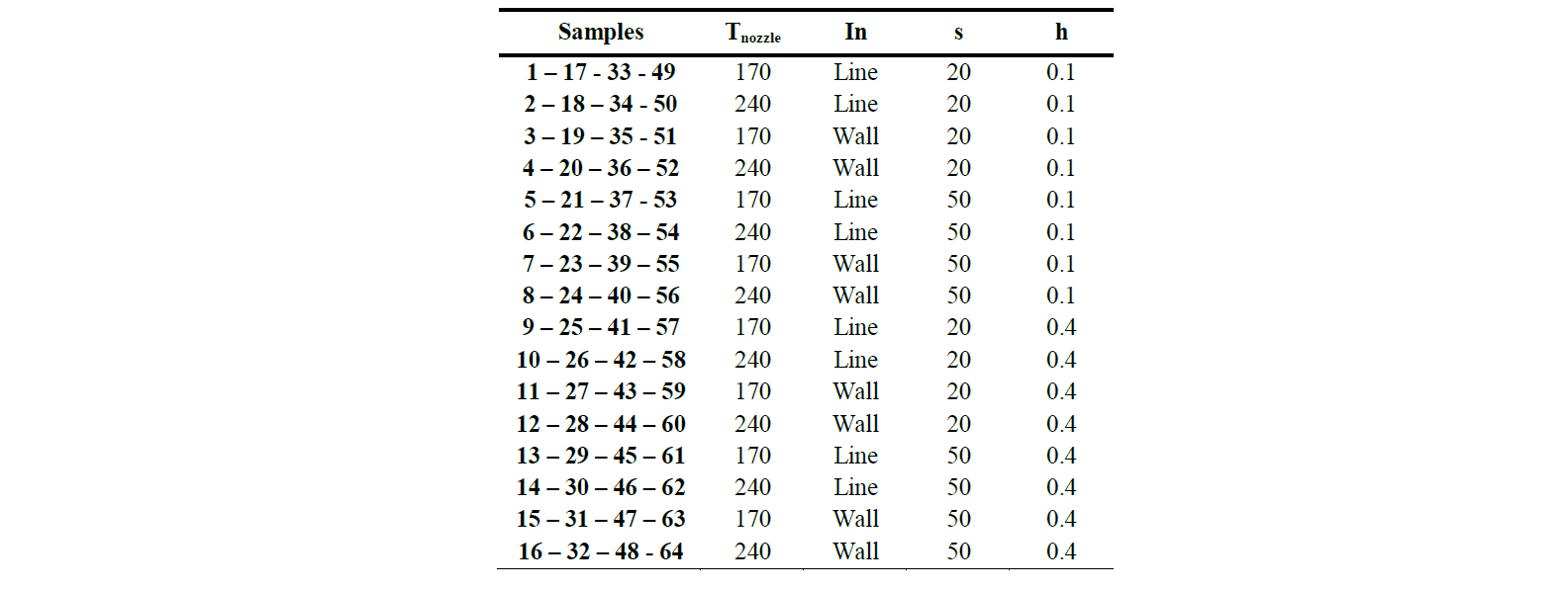
A prism with dimensions equal to 17.9x17.9x18.3 mm was selected as reference sample. A 24 full factorial design of experiments (DoE) was taken into account, varying the nozzle temperature (𝑇𝑛𝑜𝑧𝑧𝑙𝑒), the infill type (𝐼𝑛), the print speed (𝑠) and the layer thickness (ℎ) on 2 levels (low and high - Table 1). 𝐼𝑛 represents the movement of the nozzle while filling the inner part; the selected patterns are reported in Table 1. 𝑠 refers to the speed of the extruder movement and ℎ represents the height of the single deposited layer, which affects the quality of the parts along the growth direction (Z). Levels were defined by means of preliminary tests aimed at defining a technological window in which it was possible to print the selected material. 4 repetitions were considered for each combination of the process parameters. The infill density (100%, to evaluate the maximum reachable density) and the bed temperature (100 °C, to enhance the bonding of the first layer and to avoid the warpage phenomena) were considered as fixed parameters. Table 2 shows the 24 factorial plan displaying the combination of process parameters.
Table 1. Process parameters levels considered for the DoE

Table 2. DoE: sample identification and process parameters combinations
2.3 Shrinkage and density measurement
The samples dimensions were evaluated by means of a CMM (Zeiss O-Inspect), measuring both the green-parts and the post-processing-parts (after debinding and sintering), for calculating the differences between samples before and after the thermal treatments in terms of dimensions and geometrical volume. The measurements were performed through a touching probe, calculating the distance between the reconstructed plans and the sample volume. The measurements were repeated three times to ensure the accuracy of the procedure and to avoid random errors. Then, the average values were used as reference values for the analysis. The shrinkage due to the debinding and sintering processes was calculated as the percentage dimension reduction along the three directions, according to (1).

Where 𝑖 indicates the dimension (X, Y, Z), Dgp and Dpp are the dimensions of the green-part and the post-processing-part respectively. The 𝜌𝑏𝑢𝑙𝑘 was calculated as the ratio between the weight and the geometrical volume of the sample (2). In particular, 𝑉𝑡ℎ𝑒𝑜 is the volume of the post-processing-part after thermal treatments, calculated using the dimensions estimated through the CMM, and 𝑤 indicates the post-processing weight, measured using a precision balance.

2.4 Porosity evaluation
The FDM process can generate porosity into the internal structure; for this reason, the bulk density was compared with the density of monolithic AISI 316L (𝜌𝐴𝐼𝑆𝐼=8 𝑔/𝑐𝑚3) and the amount of opened and closed porosity were estimated through the evaluation of liquid penetration. Specifically, the post-processing-samples were first weighed in air (𝑚1) before being immersed in a wetting liquid (1-butanol, 𝜌𝑓𝑙𝑢𝑖𝑑=0.810 𝑔/𝑐𝑚3) for 24 h to fill open porosity. Then, the samples were taken out of the solvent and their surface was quickly swabbed before weighing it in air (𝑚2). Knowing the density of the solvent (𝜌𝑓𝑙𝑢𝑖𝑑), the opened porosity fraction (𝑜𝑝 - 3) and closed porosity fraction (𝑐𝑝 - 4) of the sample were calculated.

2.5 Data analysis
To be sure of the correctness of data collection, a pre-treatment of the data was carried out by a Matlab code for identifying possible outlier values. Then, the Analysis of Variance (ANOVA) was carried out to identify a possible influence of the selected process parameters on the final indicators previously described (shrinkage along three dimensions and bulk density) considering the effect of single parameters and different degrees of interactions. A confidence interval equal to 95% was taken into account.
3 Results and discussion
The outlier analysis allows to identify and delete the data from the dataset generating an updated version of it. In Fig. 2, it is possible to compare the experimental results with the nominal shrinkages and bulk density values defined in the technical sheets (BASF and traditional AISI 316L, respectively). The black dots represent the mean values of the shrinkage estimated using the three measures collected for each sample. The trend of shrinkage along X-axis and Y-axis are very similar and close to the nominal shrinkage. A different distribution can be observed for the shrinkage along Z-axis; in fact, it is clear the presence of higher deviation from the nominal values observing a clustering as a function of the set of applied parameters.
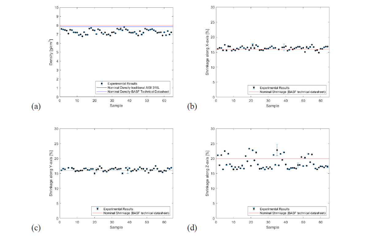
Fig. 2. Errorbar of bulk density and shrinkages
The bulk density of the post-procesed parts (Fig. 2d) appears to be, in some cases, very close to the nominal density of the monolithic AISI 316L, varying in a range between 6.7 and 7.8 g/mm3. In general, the standard deviations of the data are very small, indicating that the results of groups of measures are close each other.
The residuals demonstrated, in all cases, to be normally distributed and randomly scattered with an average value near to zero. The ANOVA results show that the single parameters affect, in each case in a different way, the indicators, while only a few 3-way interactions affect the indicators (Table 3). In particular, the bulk density is not affected by the 𝑇𝑛𝑜𝑧𝑧𝑙𝑒, as a single parameter but it plays an important role from the interaction point of view, especially as regards its interaction with the infill type and the layer thickness. Each shrinkage is affected differently; in general, speed is the factor that affects all shrinkage directions, but, while shrinkage along X-axis shows an effect derived from layer thickness, the shrinkage along Z-axis shows also an effect due to the 𝑇𝑛𝑜𝑧𝑧𝑙𝑒, which influences also the adhesion of the layers along the growth direction.
Considering the material involved in this process, the optimal results are represented by obtaining the highest bulk density, close to the monolithic AISI 316L (8 g/cm3). The main effects plot (Fig. 3) shows the parameters combination satisfying this requirement: 𝐼𝑛 = Line infill, 𝑠 = 20 mm/s and ℎ = 0.1 mm, regardless of the 𝑇𝑛𝑜𝑧𝑧𝑙𝑒 value. This is also confirmed by the graph reported in Fig. 4. Where the average values and the standard deviation (of 4 runs) of bulk density are reported as a function of process parameters combination. Both Fig. 4 and Fig. 5 show a low standard deviation indicating stability and repeatability of the process.
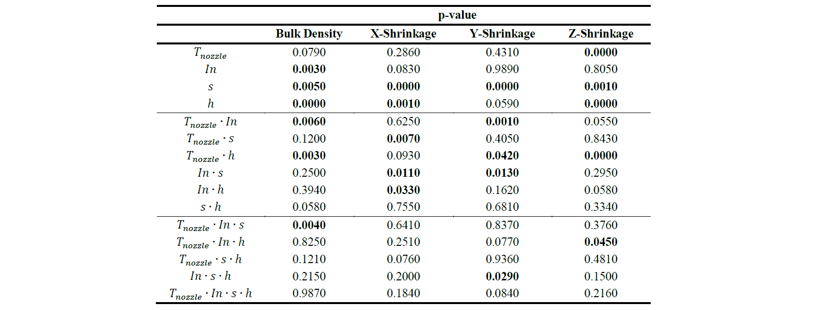
Table 3. ANOVA p-values
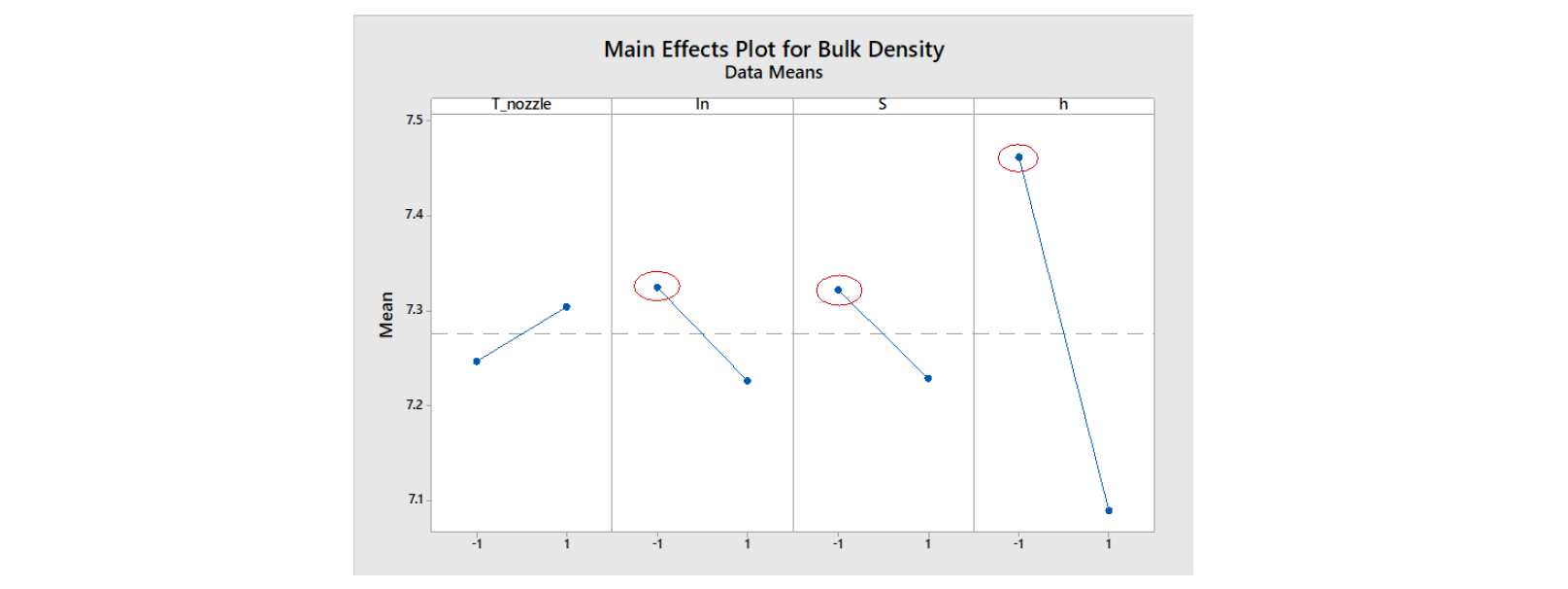
Fig. 3. Main effects plot for bulk density
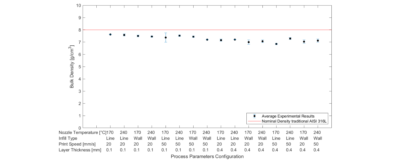
Fig. 4. Aggregate data of bulk density as a function of process parameters
The shrinkage percentage along X and Y axis are closer to the declared nominal value (technical datasheet) and are characterized by a very similar behavior, as observable by the near-perfect overlap of the trends. On the contrary, the shrinkage along Z-axis shows a greater dispersion and a different behavior can be identified fixing the layer thickness. Samples with ℎ=0.4 mm show a trend lower than the nominal value (~16.90%), while samples with ℎ=0.1 mm show an effect due to the interaction of ℎ with the 𝑇𝑛𝑜𝑧𝑧𝑙𝑒. Samples obtained with the lowest temperature have a higher shrinkage along Z-axis, whith respect to those realized with the highest temperature (evidences supported by p-value reported in Table 3).
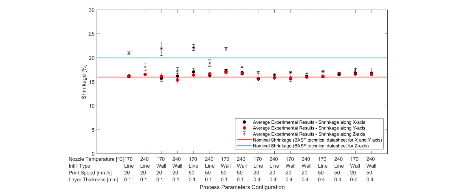
Fig. 5. Aggregate data of shrinkage along X, Y and Z - axis as a function of process parameters
To set the real density and structure of the material, the volume percentages of opened and closed porosity were evaluated as a function of the geometrical volume estimated by means of a CMM. To identify any different behavior in the distribution of metal particles, the porosities evaluation was conducted for samples printed with optimal parameters and samples characterized by the lowest bulk density. Differences in the structures are evident (Fig. 6): the samples with the worst bulk density show a higher percentage of opened porosity, indicating a not optimal layer adhesion and imperfection on the external surfaces. On the other side, the percentage of closed porosities between the samples printed with optimal parameters is very small, showing an opened porosity percentage equal to 2.50% and 2.70% for 𝑇𝑛𝑜𝑧𝑧𝑙𝑒 equal to 240°C and 170°C respectively. Therefore, this result allows defining the application of the low temperature of the nozzle as a better solution.
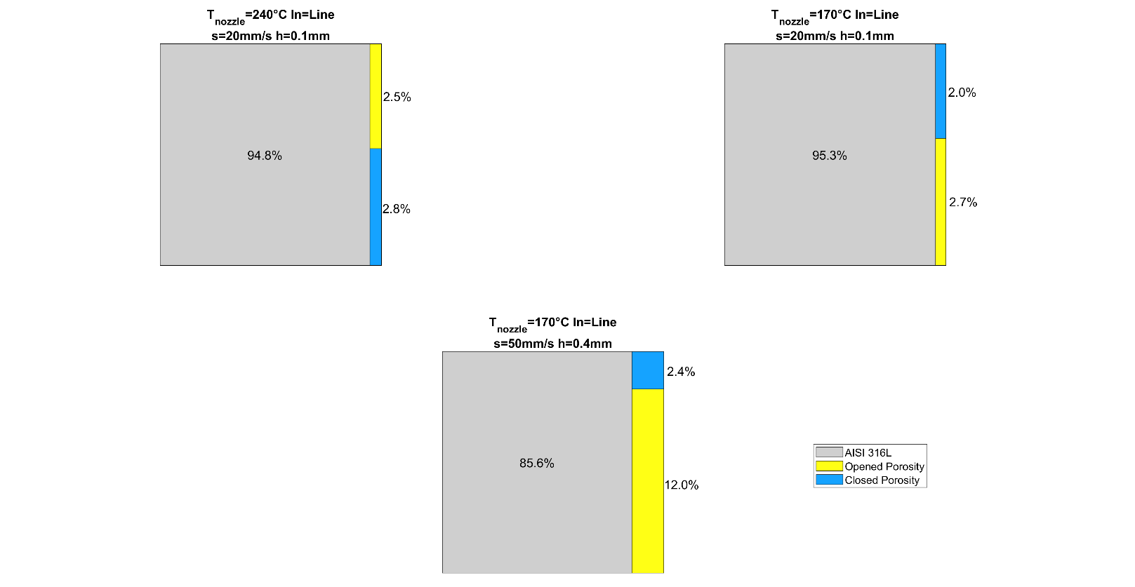
Fig. 6. Treemap of ratio between percentages of AISI 316, op and cp volume
4 Conclusions
This study introduced the application of a metal filament on a low-cost FDM machine, permitting a faster and less expensive process than the existing metal AM technology. Both the bulk density and the shrinkage were affected by the printing parameters, moreover, it was found that shrinkage along X and Y directions has a similar behavior (about 16.40%), while the effects due to the thermal treatments was more critical along the Z-axis in terms of both shrinkage value and scatter. This is mainly due to the effect of the layer thickness and the interaction between the temperature and the infill type. The best combination was found for a line infill, ℎ=0.1 𝑚𝑚 and 𝑠=20 𝑚𝑚/𝑚𝑖𝑛 which gives rise to a shrinkage along Z-axis equal to 20%. Therefore, a print characterized by a low speed of material feeding and growth (low layer thickness) leads to better results in terms of density.
Considering these evidences, the use of a metal filament in FDM process is a promising way of making non-critical metal AM parts and deserves further investigations, also thanks to its cost-efficiency. In particular, it was shown that it is possible to convert a commercial FDM printer, typically used for polymeric materials, into a printer for metal filament by setting the machine with a nozzle with higher wear resistance. This may represent a sustainable solution for both the economical aspect and the simplicity of production of parts having complex geometry.
