1 Introduction
One of the foremost limiting factors in titanium forming is friction, which leads to severe adhesive wear, ultimately resulting in poor surface finish of formed parts or, worse, an interrupted process due to damaged tools. A good understanding of friction conditions is also necessary for accurate utilisation of finite element analysis (FEA). One method of determining friction and the effectiveness of lubricants is the ring compression test. This relatively straightforward test involves the compression of a ring-shaped test sample and measuring the change in its internal diameter – the basic concept being that with zero or low friction, the internal diameter would increase, but at higher friction values, the internal diameter would decrease. The change in internal diameter for each sample can then be compared to a set of calibration curves generated by an FEA simulation of an identical process, repeated with varying friction coefficients, in order to determine the friction coefficient experienced during the physical test [1].
In the current work, a ring compression experiment was designed to study the effect of three specific factors over which the operator has complete control – the choice of lubricant, the way the workpiece surface is prepared prior to applying the lubricant, and the tool coating selected. An effective lubricant can decrease friction by providing a physical barrier between the surface of the workpiece and the tools. For warm forming of commercially pure titanium (CP Ti), there appears to be no ideal lubricant, but those used are often based on graphite or molybdenum disulphide (MoS2) [2-4]. Another option, less prevalent in the academic literature but similar in nature to MoS2 and with arguably better tribological benefits, is tungsten disulphide (WS2) [5-6]. Preparing the workpiece surface can improve its ability to retain lubricant throughout the forming process. One possible method is sandblasting, which roughens the surface using a stream of abrasive particles [7]. Another proposed method is Micro-Arc Oxidation (MAO), sometimes known as Plasma Electrolytic Oxidation. MAO is an electro-chemical oxidation process which, through the creation of plasma on the surface of a part, results in the growth of a hard-yet-ductile ceramic oxide layer. This oxide layer supposedly improves, amongst other properties, the wear resistance of the surface treated. MAO coatings have been demonstrated to: create appropriately-sized surface pores to retain solid lubricant on the workpiece surface throughout forming [4], reduce friction in sliding conditions when used in combination with a graphite-based lubricant [8-9] and provide greatly superior wear resistance to conventionally anodised surfaces [10]. There is also interest in the ability of hard tool coatings to minimise friction and adhesive wear. For titanium, it has been suggested that only nitride-type coatings improve galling performance, with plasma nitriding providing a small yet reasonable improvement [11].
2 Materials and Methods
2.1 Materials
27 ring samples, with the dimensions shown in Fig. 1, were produced from a single plate of grade 2 commercially pure titanium with the composition provided in Table 1.
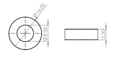
Fig. 1. Ring compression specimen geometry and dimensions
Table 1. Typical composition (including impurities) of Grade 2 CP-Ti
|
Composition |
C |
H |
O |
N |
Fe |
Ti |
|
Analysis (%) |
≤ 0.08 |
≤ 0.015 |
≤ 0.25 |
≤ 0.03 |
≤ 0.30 |
Balance |
9 of the rings were subjected to sandblasting in a Fox 50 blasting cabinet from Vixen, with sand as the abrasive media and all surfaces being evenly exposed. A further 9 rings were subjected to Micro-Arc Oxidation by IBC Coatings Technologies Inc., USA [12]. Both processes resulted in considerably higher surface roughness with negligible change to specimen geometry. The remaining 9 rings were maintained in their as-received state to serve as a control group.
Prior to testing, each of the rings were coated according to one of three lubrication methods:
-
Spray-coated evenly with dry molybdenum disulphide (MoS2) lubricant, supplied by Ambersil [13], and allowed to dry fully.
-
Spray-coated evenly with a mixture of one part water and two parts Durcol W1040-02 microcrystalline graphite-based lubricant, supplied by James Durrans & Sons Ltd. [14], which is allowed to fully dry before being brushed with Loctite 8009, a graphite-based anti-seize lubricant from Henkel [15].
-
Brushed with a high temperature grease comprising of tungsten disulphide (WS2) in a synthetic oil base, supplied by Lower Friction [16].
Six identical upsetting dies were produced from Vanadis 23 tool steel (AISI M3:2/W.-Nr 1.3344), supplied by Uddeholm with the composition provided in Table 2.
Table 2. Typical composition of Vanadis 23 tool steel
|
Composition |
C |
Cr |
Mo |
W |
V |
Fe |
|
Analysis (%) |
1.28 |
4.2 |
5.0 |
6.4 |
3.1 |
Balance |
As shown in Fig. 2, the dies were designed with flat work surfaces for simple open-die upsetting of small ring samples, with a small thermocouple hole for ensuring consistent temperature throughout testing. All die worksurfaces were ground and polished to a mirror finish using a series of abrasive papers, diamond solution and colloidal silica. The final die surfaces were then treated as follows:
-
Two dies were subjected to plasma nitriding for 10 hours at 500 °C, with processing conditions chosen to not produce any compound layer, and then polished again to a mirror finish.
-
A further two dies were subjected to a duplex treatment consisting of plasma nitriding for 10 hours at 500 °C, followed by polishing, an additional plasma vapour deposition (PVD) coating of chromium nitride (CrN), and a final polishing. Processing conditions were chosen in order to produce a compound layer.
-
Two dies were maintained in their polished state with no further surface treatment.

Fig. 2. Ring compression die geometry and dimensions
The final surface roughness measurements for each batch of ring specimens and dies were measured using a Mitutoyo Surftest SV-2000 and the mean values are provided in Table 3. Plasma nitriding and PVD coating treatments were carried out by Hauck Heat Treatment, UK [17].
Table 3. Mean roughness values for ring specimens and dies
|
Surface |
Arithmetic Mean Roughness, RA (μm) |
|
Ring Specimens (as received) |
1.326 |
|
Ring Specimens (sandblasted) |
2.463 |
|
Ring Specimens (Micro-Arc Oxidation) |
8.527 |
|
Dies (no coating) |
0.064 |
|
Dies (plasma nitrided) |
0.010 |
|
Dies (plasma nitrided + CrN PVD) |
0.010 |
2.2 Experimental Plan
A full factorial experiment, based on the design of experiments methology laid out by Groves and Davies [18], was designed. Three factors (lubricant, specimen preparation method and tool coating) were each assigned one of three levels, coded as (-), (0) and (+), as designated in Table 4. In order to measure the effect of each factor, the resulting friction coefficient was chosen as the quality characteristic. 27 trials were required to investigate every possible combination of factor levels and allow for full analysis of the effects of each factor and any possible interaction between them.
Table 4. Experimental control factors and their assigned levels
|
Factor Level |
Lubricant |
Specimen Preparation |
Tool Coating |
|
- |
Graphite |
None |
None |
|
0 |
Tungsten Disulphide |
Sandblasted |
Plasma Nitriding |
|
+ |
Molybdenum Disulphide |
Micro-Arc Oxidation |
Plasma Nitriding + |
2.3 Experimental Procedure
Ring compression tests were carried out on a 250 kN hydraulic press using a simple compression toolset. The tools were heated to and maintained at 300 °C for all trials using two 2.2 kW band heaters. Prior to upsetting, each ring was held in contact with both dies for 15 minutes to allow the specimen to reach the target processing temperature of 300 °C. The upper die would then retract marginally before descending steadily at 2 mm/s to upset the specimen by 50%. Afterwards the upper die would be retracted, and the deformed specimen removed, allowed to air cool to room temperature and cleaned with white spirit. The final inner diameter was then measured in five different directions using a digital Vernier caliper and the mean value calculated for comparison with the simulated calibration curves. The final height of each sample was measured with a digital micrometer so that any variation could be accounted for during analysis. These values were used to calculate the change in internal diameter and height reduction achieved.
2.4 Finite Element Analysis
To produce a set of calibration curves, showing percentage height reduction against percentage internal diameter reduction, against which to compare the empirical results, the ring compression process was replicated using the commercial FEA code ABAQUS/Explicit. The process was modelled as an axisymmetric problem with the ring represented by half of its cross-section, and the dies represented by analytical rigid line segments. The problem was modelled as an isothermal process. The ring was meshed using CAX4R elements. Fig. 3 shows the flow stress curve used for grade 2 CP-Ti, produced using material data gathered at the Advanced Forming Research Centre by means of compression testing at 300 °C at a strain rate of 1.0 s-1 [19]. The yield criterion utilized in the model was the von Mises criterion. The interactions between the ring surfaces and the dies were defined using the Coulomb friction law with the friction coefficient input varied by 0.005 between each run of the simulation in order to plot the deformation of the ring for a wide variety of friction conditions. For each run, the change in both the height and internal diameter of the ring at the midpoint were recorded.
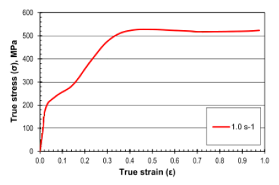
Fig. 3. True stress-strain curves obtained for grade 2 CP-Ti by uniaxial compression testing at 300°C at strain rates of 0.01, 0.1 and 1.0 s-1
3 Results and Analysis
Early comparison with simulated results showed that all experimental data points fall within the range of 0.03 – 0.19 in terms of friction coefficient, therefore it is this range that was plotted most closely, with a focus on the internal diameter at approximately 50% height reduction. Calibration curves for friction coefficients from 0.0 – 0.1 and 0.1 – 0.195 are shown in Fig. 4 and Fig. 5, respectively. The ring measurements from the experimental trials have been superimposed onto the graphs, allowing for the friction coefficient to be approximated to 3 decimal places for each trial. These are shown in Table 5.
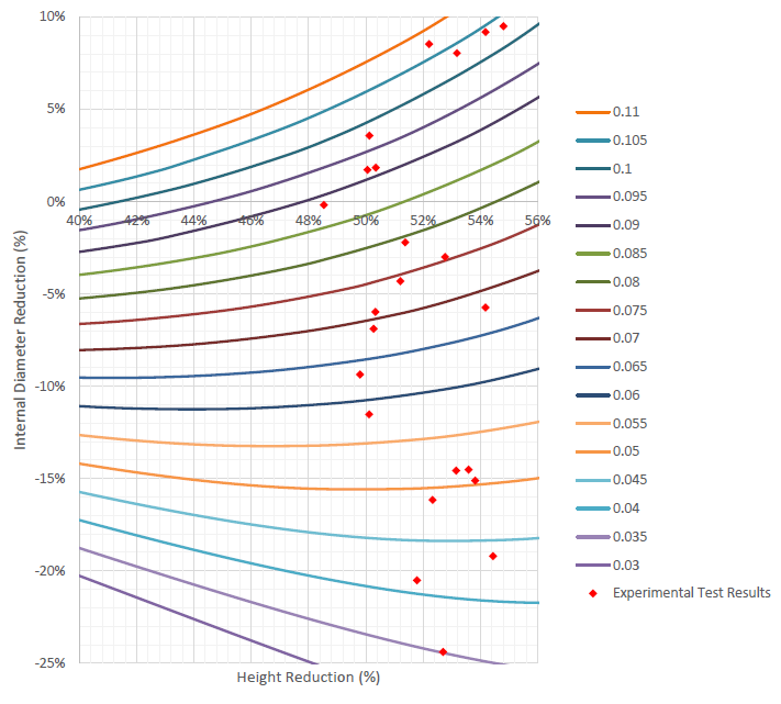
Fig. 4. Generated calibration curves for 0.0 – 0.1 friction coefficient with superimposed measurements from physical ring compression trials
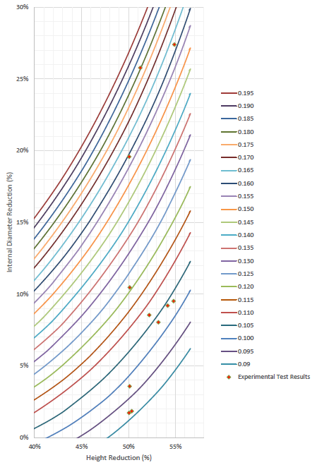
Fig. 5. Generated calibration curves for 0.1 – 0.195 friction coefficient with superimposed measurements from physical ring compression trials
Table 5. Friction coefficients determined for each experimental trial
|
FACTOR 1 |
FACTOR 2 |
FACTOR 3 |
QUALITY CHARACTERISTIC |
|
|
Trial Number |
Lubricant |
Specimen Preparation |
Tool Coating |
Friction Coefficient |
|
1 |
Graphite |
None |
None |
0.049 |
|
2 |
Graphite |
None |
PN |
0.035 |
|
3 |
Graphite |
None |
PN + PVD |
0.042 |
|
4 |
Graphite |
Sandblasted |
None |
0.051 |
|
5 |
Graphite |
Sandblasted |
PN |
0.044 |
|
6 |
Graphite |
Sandblasted |
PN + PVD |
0.052 |
|
7 |
Graphite |
MAO |
None |
0.104 |
|
8 |
Graphite |
MAO |
PN |
0.068 |
|
9 |
Graphite |
MAO |
PN + PVD |
0.052 |
|
10 |
WS2 |
None |
None |
0.080 |
|
11 |
WS2 |
None |
PN |
0.071 |
|
12 |
WS2 |
None |
PN + PVD |
0.063 |
|
13 |
WS2 |
Sandblasted |
None |
0.076 |
|
14 |
WS2 |
Sandblasted |
PN |
0.075 |
|
15 |
WS2 |
Sandblasted |
PN + PVD |
0.059 |
|
16 |
WS2 |
MAO |
None |
0.108 |
|
17 |
WS2 |
MAO |
PN |
0.069 |
|
18 |
WS2 |
MAO |
PN + PVD |
0.092 |
|
19 |
MoS2 |
None |
None |
0.098 |
|
20 |
MoS2 |
None |
PN |
0.104 |
|
21 |
MoS2 |
None |
PN + PVD |
0.089 |
|
22 |
MoS2 |
Sandblasted |
None |
0.121 |
|
23 |
MoS2 |
Sandblasted |
PN |
0.104 |
|
24 |
MoS2 |
Sandblasted |
PN + PVD |
0.092 |
|
25 |
MoS2 |
MAO |
None |
0.180 |
|
26 |
MoS2 |
MAO |
PN |
0.162 |
|
27 |
MoS2 |
MAO |
PN + PVD |
0.160 |
The average response recorded for each factor at each level is plotted in Fig. 6. Varying the lubricant appears to make a large difference to the friction coefficient while the tool coating appears to have produce a relatively small effect. In terms of specimen preparation, no preparation and sandblasting appear to produce similar results while micro-arc oxidation in this case has a noticeable negative effect on friction.
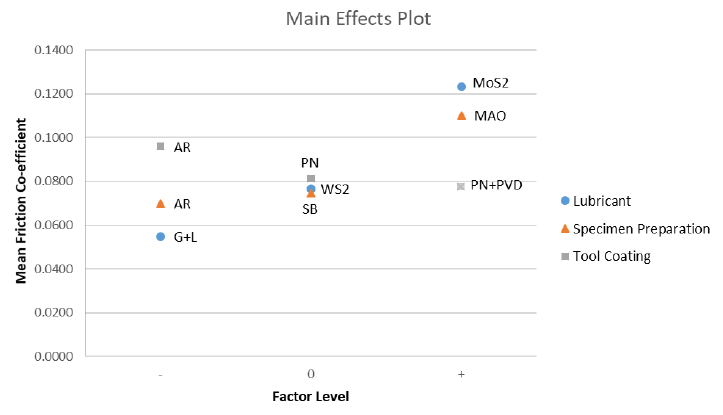
Fig. 6. Main effects plot showing mean friction coefficient for each factor at each level
To determine which factors are statistically significant, the statistical methods recommended by Grove and Davies were followed [18]. An orthogonal array was created to statistically separate the effects of varying each factor. For a full factorial experiment of this size, the L27(313) array is used, which accounts for all possible effects as well as any interaction within factor pairs. Both normal and half-normal plots were used to identify effects likely to be statistically significant. These were then analysed further using ANOVA and F-tests. The effects identified as statistically significant, with the significance level (α) set to 5%, were, in order of significance:
-
The linear effect of the lubricant, and
-
The linear effect of the specimen preparation.
As this experiment investigates purely qualitative factors, no interpolation or extrapolation of data is possible – it is not possible to formulate a meaningful prediction equation based on the results. This is because, in the case of qualitative factors, there is no smooth transition between factor levels, so predicted points between and beyond the investigated levels have no practical value and therefore are not included in this study.
4 Discussion
After analysing the data, it is possible to determine which combinations of parameters result in the lowest friction. Table 6 lists the five configurations with the lowest friction coefficient in increasing order.
Table 6. Factor combinations resulting in the lowest friction
|
Lubricant |
Specimen Preparation |
Tool Coating |
Observed Friction Coefficient |
|
Graphite |
None |
PN |
0.035 |
|
Graphite |
None |
PN+PVD |
0.042 |
|
Graphite |
Sandblasted |
PN |
0.044 |
|
Graphite |
None |
None |
0.049 |
|
Graphite |
Sandblasted |
None |
0.051 |
The choice of lubricant was shown to be the most significant factor during the analysis of variance and F-tests. For all specimen preparation methods and tool coatings, the graphite-based lubricant proved to be the most effective at reducing friction at 300°C.
The MoS2-based lubricant, on the other hand, consistently resulted in higher friction. The WS2-based lubricant was, in most cases, a close second behind the graphite-based lubricant, although still consistently and significantly worse.
The effect of the specimen preparation method was also a significant factor. Micro-arc oxidation notably resulted in the highest friction in all cases, directly contradicting the conclusion reached by Wang et al [9]. This is likely due to the relatively high surface roughness of the samples subjected to this treatment. It is possible that with careful polishing after micro-arc oxidation to reduce the roughness, the treated surface would exhibit some tribological benefits. The suitability of the MAO process in this context therefore requires further study. The difference in friction between sandblasted samples and those left in their as-received condition was negligible.
The effect of varying tool coating was found to be statistically insignificant in this case. However, both coated die sets did exhibit marginally lower friction than the uncoated dies for all lubricants and methods of specimen preparation. This may be due to the lower surface roughness of the treated dies rather than any specific properties of the coatings. The difference between plasma nitriding alone and the duplex treatment was negligible.
The findings of this experiment provide important information which may help control the friction conditions experienced during warm forming of CP-Ti and its alloys. It can be seen from the results that careful selection of an appropriate lubricant can lead to large improvements in friction behaviour, and that graphite-based lubricants are to be recommended. Also, the evidence suggesting that billet surface modification leads to only modest improvement or even harm may help to avoid redundant or counterproductive operations being carried out by researchers and manufacturers, thus saving time and resources, and potentially improving output results. Micro-arc oxidation should be avoided unless trials are carried out to determine whether a suitable polishing procedure or other post-processing can provide better results. Furthermore, due to the marginal changes in friction attributed to adding hard nitride coatings to steel tools, such procedures are unlikely to be cost-effective. The cost of such treatments can be high while the benefits provided are low. The appeal of such coatings may be further diminished by the potentially complex geometries of tools in practical applications, as opposed to the extremely basic dies tested in this study, which may complicate the coating process. Unless adhesive wear is eliminated entirely, these coatings would also deteriorate during use and need replacing, which in certain situations may prove prohibitively expensive or time-consuming.
While the current study provides an indication of which factors are significant when attempting to reduce friction during the warm forming of titanium, it is recommended that further study is carried out to test a wider variety of lubricants, preparation methods and tool coatings for a more complete understanding of the optimum processing conditions.
5 Conclusions
From the experiment conducted and the subsequent analysis, it was possible to draw the following conclusions:
-
Factors producing a significant effect on friction between a CP-Ti workpiece deformed plastically at 300°C and a steel tool include, in order of statistical significance, the lubricant selected and the method of specimen preparation.
-
Of the three lubricants tested, the graphite-based lubricant resulted in the lowest friction, followed closely by the WS2-based lubricant, with the MoS2-based lubricant resulting in the highest friction.
-
Of the three specimen preparation options tested, no preparation and sandblasting both resulted in low friction, with sandblasting providing better results for the WS2-based lubricant, and no preparation being optimal for the graphite- and MoS2-based lubricants. Specimens subjected to micro-arc oxidation exhibited comparatively high friction.
-
Coated tools appeared to marginally reduce friction, although this may be a result of the variation in surface roughness rather than any specific properties of the coatings.
-
The combination of parameters predicted to minimise friction is therefore a graphite-based lubricant applied to an untreated specimen surface in contact with a smooth, hard-wearing tool coating such as plasma nitriding or a PN + CrN PVD duplex treatment.
-
The optimal parameters outlined in this study may improve titanium forming processes by reducing the risk of severe adhesive wear and other friction-related problems.
Acknowledgements
This work was supported by the Engineering and Physical Sciences Research Council (EPSRC) as part of an Engineering Doctorate study. The authors would also like to thank the staff at the Advanced Forming Research Centre, part of the National Manufacturing Institute Scotland, for their support.
