1 Introduction
The control of microstructure during the manufacturing process of engineering components is critical to achieve the necessary mechanical properties required for the final application. The thermo-mechanical loads involved during the ingot-to-billet conversion route must permit the complete recrystallisation of the as-cast structure. Thus, accurate characterisation of thermo-mechanical and microstructural properties of the as-cast material are essential to obtain an optimised and economical manufacturing route guaranteeing the quality of the products.
Laboratory-scale tests are used for the material characterisation of small samples (< Ø 20 x 20 mm) since they permit precise measurements of load and displacement under complex thermo-mechanical loads. The experimental results are used to develop and calibrate the constitutive models governing the material thermo-mechanical and microstructural properties [1], [2]. These can then be implemented in Finite Elements (FE) models to design and optimise relevant manufacturing routes.
Due to the solidification process of the as-cast material, its microstructure and behaviour are however specific. The microstructure is composed of coarse and elongated dendritic grains with a preferential crystallographic orientation aligned with the direction of solidification, which can lead to anisotropic plastic behaviour [3]. Chemical segregation and different mechanical behaviour of the phases composing dendritic and inter-dendritic grains can also lead to flow localisation and to heterogeneous recrystallisation [4]. Thus, the evaluation of the thermo-mechanical path and the evolution of the microstructure during the ingot-to-billet conversion process of the as-cast material remains challenging and consequently impedes the design and optimisation of the industrial manufacturing process.
This study aims to supplement the as-mentioned techniques for the characterisation of the as-cast material behaviour. As-cast type 316 austenitic stainless steel behaviour is investigated through hot compression tests on Ø 60 × 60 mm samples extracted from an ingot. A FE model considering the anisotropic behaviour of the material is developed to predict the strain repartition in the samples during upsetting, and the heterogeneous recrystallisation behaviour of the as-cast microstructure is revealed, at the scale of the samples, using advanced image analysis methods. Hereby, the feasibility of this methodology is demonstrated.
2 Material
The present investigations are focused on a Niobium-stabilised type 316Nb austenitic stainless steel. An as-cast ingot with ≈ Ø 185 x 550 mm dimensions was produced through consecutive vacuum induction melting (VIM) and vacuum arc re-melting (VAR). The solidification microstructure of the ingot along transverse and longitudinal sections is shown in Fig.1 a). As shown in Fig.1 b), the as-cast microstructure is composed of coarse, elongated dendritic grains, oriented predominantly radially at ≈ 60° from the axis of the ingot although grains at the core of the ingot are aligned with the axis. This appearance depends on the cooling rates and progression of re-melting [5]. Cylindrical samples for upsetting tests were extracted by Electro Discharge Machining (EDM) from the as-cast ingot, and machined to final dimensions. As shown in Fig.1 a), the samples are described as axial and radial with their axis parallel and perpendicular to the axis of the ingot, respectively, to study the influence of the upsetting direction with respect to the as-cast grain orientation. Their microstructures, at the size scale of the samples, are presented in Fig.1 c) and d), respectively. The samples had dimensions of Ø 60 x 60 mm to reduce the effect of their microstructure on their deformation by increasing the number of grains/volume of material, and a 1:1 height to diameter ratio to limit their temperature gradient prior to non-isothermal upsetting tests.
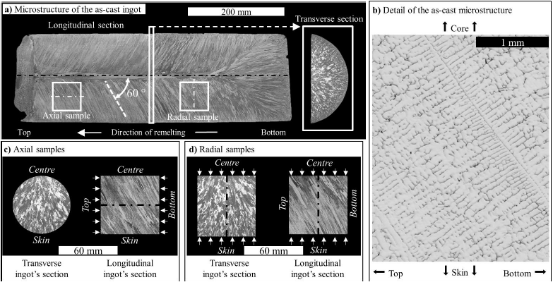
Fig.1: Microstructure of a) the as-cast VIM/VAR processed ingot, with indicative position and orientation of axial and radial samples. b) Detail of the coarse dendritic as-cast microstructure. Overview of the microstructure along the entire longitudinal and transverse sections of the c) axial and d) radial samples. The direction of upsetting are indicated by arrows.
3 Methodology
3.1 Upsetting tests
All samples were subjected to different deformation levels by upsetting, to 20, 30, and 50 % height reduction (upsetting) ratios. The axial samples were heated to 1100 and 1200°C prior upsetting, and the radial samples were only heated to 1200°C. The transfer of the samples from the furnace to the dies was measured between 3 and 4 seconds, and the holding time on the anvils, heated to 400°C, lasted between 4 and 10 seconds prior upsetting. A 500 Tons (T) capacity hydraulic press, controlled with a constant strain-rate of 0.1 s-1, was used for the upsetting trials. The load applied by the press and the position of the upper ram were recorded during forging, with a resolution of 0.5 T and 0.5 mm, respectively. Lubrication with a mixture of water and graphite slurry was used to reduce the effect of friction between the samples and the dies during the trials. The samples were then quenched immediately after upsetting, to freeze their microstructures for subsequent analysis of the Dynamic Recrystallization (DRX).
3.2 Microstructural analysis
The deformed samples were cut along their longitudinal axis and prepared for light Optical Microscopy (OM) using standard metallographic sample preparation techniques. The microstructures were revealed by electro-etching using 10 % (wt) oxalic acid as electrolyte and by applying 6 volts, as per [6]. OM micrographs were collected at ×5 magnification, and stitched together to reconstruct the full cross-sectional image of the deformed samples. Each micrograph represent a 1.9 × 2.5 mm zone. The grain and grain boundaries are detected using an in-house watershed segmentation routine developed in Matlab® R2018a. Recrystallised and non-recrystallised grains were identified on each micrograph by defining a grain surface area threshold below which they are considered as recrystallised, and the average fraction of recrystallised grains in the micrograph was measured. The process is repeated for each micrograph, and the results were exported as large single images, giving an overview of the progress of recrystallisation in the samples.
3.3 FE analysis
A FE model was developed in the commercial FE software Forge® NxT 3.0 by Transvalor® to describe the upsetting trials. The transfer time and holding/dwelling duration used in the FE model were those measured during the testing. The friction coefficient between the sample and the dies was modelled by a Coulomb's law limited to Tresca, with the parameters 𝜇 = 0.15 and 𝑚̅ = 0.3, as indicated by Forge® database for a water and graphite lubrication. The heat transfer coefficient with the dies was set to 7500 W.m-2.K-1. The kinematic behaviour of the dies during upsetting simulation was based on that recorded by the press. The material behaviour was modelled by the simplified Hensel-Spittel thermo-viscoplastic law, presented in equation (1), with the parameters given by Forge® database for the AISI 316 Nb, given in Table 1.

Table 1 : Values of the parameters of the simplified Hensel-Spittel equation given by Forge® database for the AISI 316 Nb
|
Parameter |
A |
m1 |
m2 |
m3 |
m4 |
|
AISI 316 Nb |
4660.0156 |
-0.00311 |
-0.09996 |
0.09794 |
-0.06481 |
The orthotropic Hill-48 yield criterion [7] was implemented into the FE model to account for the material’s plastic anisotropic behaviour. Assuming that the anisotropy was related to the preferential orientation of the grains, the anisotropy axis were defined as shown in Fig. 2 a), where the axis “A3” was aligned with that of the grains. To consider the symmetry of microstructure evolution around the axis of the ingot, and therefore that of the system of the anisotropy axes, a dedicated user-variable routine developed by Transvalor® was used in the FE model. A marking grid aligned with the orientation of the microstructure is also implemented into the FE model to evaluate its deformation during the upsetting tests, according to Fig. 2 b).
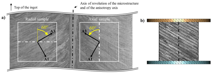
Fig. 2: Consideration of the material microstructure in the FE model: a) definition of the anisotropy axis and b) implementation of a marking grid for an axial sample, according to the orientation of the microstructure
The expression of the Hill-48 yield criterion is given by equation (2). The set of parameters required to describe the anisotropic plastic behaviour, defined by a “trial and error” approach so that the shape of the samples matched with that predicted by the simulation.

4 Results and discussions
4.1 Geometry of the samples after upsetting
Example of samples after forging are presented in Fig. 3. The deformed samples have a non-axisymmetric shape, and owing to the anisotropic plastic behaviour of the as-cast material. The irregularities on their surface can be ascribed to the coarse grain size. The lateral surface of the samples forged with the highest upsetting ratio of 50 % is shown to fold on the surface of the dies during forging.
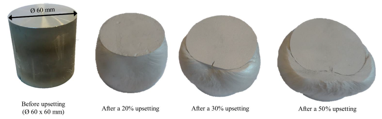
Fig. 3: Radial samples before and after forging to the indicated upsetting ratios. Dimension of the samples before forging : Ø 60 x 60 mm
3D meshes of the samples after forging were generated by stereovision using an ATOS III ScanGOM system. The 3D meshes of the axial and radial samples, heated to 1200°C prior a 30 % upsetting, are presented in Fig. 4 a) and b), respectively. Since the distribution of the microstructure in axial and radial samples is different with regard to the upsetting direction, and because of the preferential orientation of the as-cast microstructure, the deformation of axial and radial samples is different.
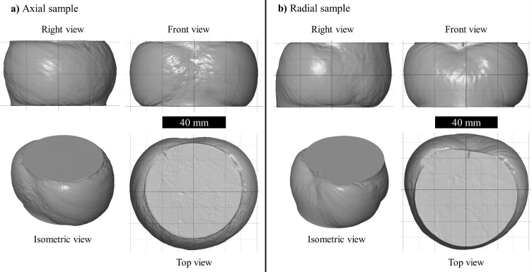
Fig. 4: 3D meshes of the a) axial and b) radial samples heated to 1200°C prior to a 30 % upsetting
4.2 Data recorded by the press: forging loads and upsetting ratios
The data recorded by the press during upsetting of the axial and radial samples are presented in Fig. 5 a) and b), respectively. The experimental process shows a good repeatability; the experimental data obtained for each condition, including temperatures and samples orientations, overlap regardless of the upsetting ratio. This demonstrates the advantage of using large-size samples with regard to the representative microstructure and volume for the investigation on the as-cast material. The small deviation of the load recorded for the radial sample forged to a 20 % upsetting ratio can originate in the specificities of the microstructure of this sample or in the non-isothermal testing conditions. Axial and radial samples appear to require a similar forging load (≈ 80 T), although the orientation of their initial microstructures and the direction of the applied load were different. Despite of the specific rotational symmetry of the initial microstructure, the respective microstructure of the samples had significant differences. It is therefore more than likely that the tests carried out on these samples are not able to capture the grain orientation dependency of the tests. The material behaviour is similar for the two main directions (i.e., radial and axial) which depend mainly on the size and alignment of grains, rather than purely grain orientation [8].
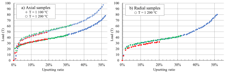
Fig. 5: Experimental data recorded by the press: a) axial, and b) radial samples
Additional investigation are required to evaluate the material flow stress, and its dependence to temperature and strain, using the results presented in Fig. 5. The current method for the determination of the stress-strain curves using results of upsetting tests are based on axisymmetric deformation and further improvements are required to comply with anisotropic plastic deformation of the samples. This would permit the development of accurate and predictive FE models.
4.3 Anisotropic FE model of Upsetting
After the “trial and error” approach optimisation, the parameters F, G, H, L, M and N, which describe adequately all upsetting ratios, were found to be those presented in Table 2.
Table 2 : Values of the parameters of the Hill-48 yield criterion
|
Parameter |
F |
G |
H |
L |
M |
N |
|
Isotropic behaviour |
0.5 |
0.5 |
0.5 |
1.5 |
1.5 |
1.5 |
|
Current anisotropic behaviour |
0.5 |
0.5 |
0.5 |
0.68 |
0.68 |
1.5 |
To evaluate the results given by the FE model, 3D meshes of the samples after forging were generated by stereovision using an ATOS III ScanGOM system. Using the commercial software GOM Inspect®, the average absolute surface distance between the surfaces of the samples after forging and that predicted by the FE model was evaluated. The shear angle of each sample, which is the angle between the direction of upsetting and the line joining the centre of their lower and upper surfaces, was measured. The results obtained for the axial and radial samples heated to 1200°C prior to 30 % upsetting are presented in Fig. 6 a) and b), respectively. A good correlation between experimental and FE results is shown. However, the comparison given in Fig. 6 b) for the radial sample show high surface distances between experimental and FE results, localised along the edge of the upper and lower surfaces of the sample. This deviation between experimental and FE results of the radial sample can be ascribed to the occurrence of shear deformation during upsetting, revealed by the high value of shear angle, seven times higher than that measured for the axial sample. The shear deformation behaviour is not predictable by the FE model, which explains the high local surface deviation shown in Fig. 6 b).
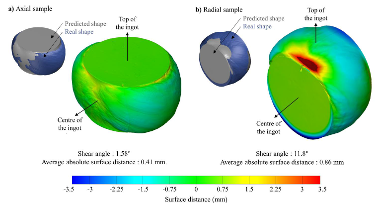
Fig. 6 : Surface distance between experimental and FE results after forging: a) axial sample and b) radial sample. Heating temperature: 1200°C, Upsetting ratio: 30 %.
These results demonstrate the capability of the FE model to predict the deformation of the samples using the orthotropic Hill-48 yield criterion, although the set of parameters have been defined by a “trial and error” approach. Investigation reported in the literature on coarse and elongated solidification microstructure have shown the anisotropic plastic deformation of as-cast material can either result from the preferential crystallographic texture, or from the specific geometrical distribution of the microstructure [8], [9]. However, the respective contribution of these two aspects have not been investigated in the present study. The further development of a CPFEM-based model can contribute to define more precisely the value of the Hill’s parameters used in the FE models. This would also permit to investigate on the sensibility of the material behaviour regarding the orientation of the solicitation, and to evaluate the respective contribution of the crystallographic and geometric orientation of the microstructure to the anisotropic plastic behaviour of the as-cast material.
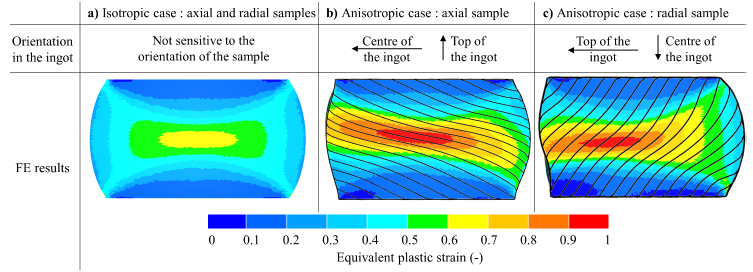
Fig. 7: Results of FE simulations for the axial and radial samples heated to 1200°C prior to a 30 % upsetting, with and without consideration of the anisotropic plastic behaviour. Results are displayed on the longitudinal section of the samples that also corresponds with that of the as-cast ingot. The upsetting axis is aligned with the vertical direction.
Since the FE model is able to predict the deformation and shape of the samples during forging (Fig. 6), the equivalent plastic strain maps in the sample was evaluated with a reasonably high confidence level. The FE results given for the isotropic case are presented in Fig. 7 a), and the anisotropic cases are presented in Fig. 7 b) and Fig. 7 c) for the axial and radial samples, respectively. The maximal value of the macroscopic equivalent plastic strain, reached for the anisotropic cases, is about 40 % higher than that predicted for the isotropic case, and its distribution is also affected by the orientation of the sample. This demonstrates the need to consider the anisotropic plastic flow of the as-cast material in the FE models to enhance the accuracy of the prediction. By comparing the deformation of the marking grid, initially aligned with the material microstructure, and the strain maps in Fig. 7 b) and Fig. 7 c), it can be observed that a relatively high strain gradient can take place in the width of one single grain.
4.4 Microstructure evolution and correlation with the FE results
Representative micrographs showing the microstructural evolution in the samples heated at 1200°C prior upsetting are presented in Fig. 8. It can be seen that the recrystallisation is promoted with increasing upsetting ratios, and strongly depends on the initial as-cast microstructure (Fig.1 b)) since the nucleation sites of the recrystallised grains are located either at the grain boundaries or at the interface with the secondary phases. Thus, the recrystallised grains are heterogeneously distributed in the samples, which is in line with the results reported in the literature for as-cast microstructures [10]–[12].
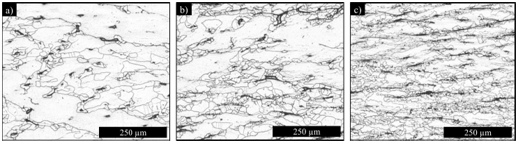
Fig. 8: Microstructure of the axial samples heated at 1200°C prior upsetting to a) 20 %, b) 30 % and c) 50 %, describing the evolution of the material microstructure with increasing upsetting ratios. Micrographs taken at the core of the samples.
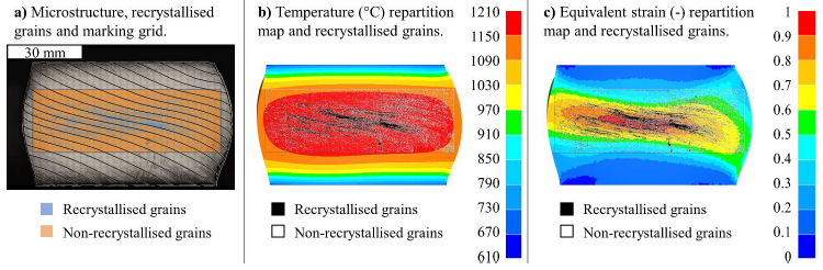
Fig. 9: Experimental identification of the recrystallised grains in the samples, overlaid on a) the temperature, b) the structure of the samples and c) on the equivalent strain distribution predicted by the FE model. Axial sample forged at 1200°C to a 30 % upsetting ratio.
Correlation of the recrystallised microstructure with the FE results is presented in Fig. 9 for the axial samples heated to 1200°C prior forging to the intermediate upsetting ratio of 30 %. Observation of the microstructure and the location of the recrystallised grains in Fig. 9 a) shows that recrystallisation occurs along strip-wise regions termed as “recrystallised bands”, oriented along the marking grid resulting from the FE simulation. This is consistent with the micrographs presented in Fig. 8, and demonstrate that the progress of the recrystallisation throughout the forging process depends on the size and orientation of the initial grains in the microstructure of the samples. The recrystallisation is more pronounced in the core of the sample, where high temperature (Fig. 9 b)) and equivalent plastic strain values (Fig. 9 c)) are predicted by the FE model. The presence of the “recrystallised bands” suggest the occurrence of flow localisation. This can lead to local strain heterogeneities and additional recrystallisation-induced anisotropy, occurring with the progress of the DRX during the deformation of the sample. This phenomenon is ascribed to the coarse dendritic microstructure of the as-cast material, and is not predictable by the FE model. Thus, evaluation of usual Johnson-Mehl-Avrami-Kolmogorov (JMAK) type equation for DRX using FE models is limited for the present material microstructure.
The results presented in Fig. 10 show the recrystallisation remains incomplete even in the central region of the samples, and the average fraction of recrystallised grains at the core of the two samples with the highest upsetting ratios is similar, close to 50 %. Local inconsistencies in the measurements presented in Fig. 10 are ascribed to the occurrence of flow localisation, promoting the recrystallisation in specific areas of the samples. Because of the heterogeneous nature of the recrystallisation in the coarse as-cast microstructure, the resolution used to evaluate the fraction of recrystallised grains can also lead to local inconsistencies of the measurements.
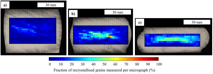
Fig. 10: Measurements of the fraction of recrystallised grains in the axial samples heated to 1200°C prior to upsetting to a) 20 %, b) 30 %, and c) 50 %.
Following the same method for the evaluation of the fraction of recrystallised grains in the radial samples, it would be possible to compare the results for the axial and radial samples, and thus to investigate the evolution of microstructure evolution throughout the upsetting and cogging operations. Among others, investigation on the evolution of the microstructure after multi-directional deformation and subsequent heat treatments are required to consider the effects of the thermal cycles involved during the industrial process. Moreover, the representativeness of the results obtained using small-scale samples taken from an as-cast ingot has to be evaluated with respect to the cogging and upsetting processes on industrial-scale ingots.
5 Conclusion
In the present study, the behaviour of Ø 60×60 mm samples taken out from a VIM/VAR processed ingot of AISI 316 Nb was investigated. A novel method was used, involving a FE model taking into account for the anisotropic plastic behaviour of the as-cast material to evaluate the strain repartition in the samples after upsetting, and the measurement of the evolution of the microstructure by image analysis. The following conclusions were drawn:
-
The recrystallised grains are either located at the grain boundaries or at the interface with the secondary phases, and are aligned along “recrystallised bands” having the same orientation as the initial microstructure.
-
The conditions involved in the upsetting tests, i.e.: 50 % upsetting at 1200°C, did not permit the complete recrystallisation of the as-cast microstructure. Thus, forging paths involving multi-directional deformations of the material and intermediate annealing heat treatment are required during the ingot-to-billet manufacturing process.
-
The global anisotropic plastic deformation of the as-cast material can be ascribed to the orientation of its specific solidification microstructure. It is implemented in a FE model to predict with a good accuracy the shape of the samples after forging, and demonstrate its non-negligible impact on the equivalent plastic strain levels and repartition in the samples. This must therefore be considered in the design process of the ingot-to-billet manufacturing routes.
-
The heterogeneous recrystallisation behaviour of the coarse and elongated as-cast microstructure cannot be correlated with the local thermomechanical loadings predicted by conventional FE models and thus, the use of mean field models for DRX, such as Johnson-Mehl-Avrami-Kolmogorov (JMAK), is unsuitable. The present paper demonstrates the limitations of the actual methods used for the design and optimisation of the ingot-to-billet manufacturing route.
Acknowledgements
The authors would like to acknowledge the support provided by Aubert & Duval. The help of Mr Jean-Baptiste MAILLET and Mr Emile DELAUNAY is greatly appreciated. The experimental works were carried out at the Advanced Forming Research Centre (AFRC), University of Strathclyde, which receives partial financial support from the UK's High Value Manufacturing CATAPULT.
