1 Introduction and motivation
Bulk metal components are often used in areas subject to very high stresses. Solid components are primarily used in sectors such as the automotive and aerospace industries. Other fields include energy technology, medical technology and general mechanical engineering. The demands on the components have increased steadily in recent years and will continue to increase in the future, in particular due to a higher demand for lightweight construction resulting from the European CO2-emission directives in the automotive industry and rising kerosene prices in the aviation industry [1]. In addition to low component weight, a smaller design and enhanced functionality as well as higher resistance to certain types of stress is also required. Currently, almost all solid components are made of monomaterials, and the choice of material being used is usually based on the highest local load. Highly stressed solid components therefore are usually made from very cost-intensive materials with high specific density and strength.
The increasing and partially contradictory demands can meanwhile hardly been met by monomaterial components. To meet the requirements, the positive properties of different materials must be combined to form a hybrid component with appropriately adapted properties. By using multi-material concepts, i.e. composites of at least two different materials, the component properties can be locally adapted to the requirement profile and lightweight design can be taken into account at the same time.
In sheet metal forming, the lightweight design concept has already been implemented in practice for some time, for example through the use of hybrid semi-finished products made of different sheet thicknesses and materials [2]. This process, which is already established on an industrial scale, was developed by Thyssen Krupp in 1985 and is now used in large quantities for the production of car body constructions [3]. In contrast, there have been hardly any approaches in bulk metal forming to further process pre-joined materials with lightweight potential using forming technology [4]. In the production of hybrid components, forging is considered to have a very high potential due to the excellent component properties and the advantages in terms of economic production. In recent years, composite forging has developed considerably for the production of hybrid components such as drive flanges [5] or gear elements [6], whereby the semi-finished products used are joined during the forging process. Hybrid bulk metal components such as connecting rods, wheel hubs and control arms are for example manufactured by Leiber Group GmbH & Co. KG, where the material composite is produced in particular by frictional and interlocking connection [7]. The authors in [8] carried out a detailed study on friction welding and subsequent forming processes using combinations of steel, aluminum and copper. The friction welded hybrid semi-finished products were upset or flank pressed. It was shown that the semi-finished products of similar or dissimilar materials can be processed with this process combination. In this context, tailored forming is a new technology that creates the potential for hybrid solid components on the basis of a new manufacturing process using pre-joined semi-finished products. The Collaborative Research Center (CRC) 1153 "Process Chain for the Production of Hybrid High-Performance Components by Tailored Forming" at Leibniz Universität Hannover has been researching new process chains for the production of innovative hybrid solid components since 2015. The planned demonstrator described in this paper is a hybrid pinion shaft, a dynamically stressed component that is subject to frequent load changes. By reducing the weight of the component it is possible not only to achieve direct weight savings but also to reduce the dimensions of auxiliary assemblies such as servo drives. The new tailored forming technology thus serves as an enabler for the implementation of an economical weight reduction through the use of the lightweight material aluminium at suitable locations. Within the scope of this study, the component weight for the planned pinion shaft can be reduced by approximately 22%, compare Fig. 1 (a). In the following chapter the tailored forming technology is presented more in detail.
The considered hybrid semi-finished product is manufactured using friction welding. The pinion shaft geometry is produced by a subsequent extrusion process. In this contribution, the bond strength of the material combination 37CrS4 and AW6082 needs to be improved so that the semi-finished components can withstand the occuring stresses within extrusion process. For this purpose, in analogy to the findings of Ashfaq et al. [9] and Behrens et al. [10], various semi-finished products differing in their weld surface geometries are produced and subsequently characterised on the basis of tensile tests. These studies shown that the bond strengths for different steel-aluminum semi-finished products, namely X5CrNi18-10/AW-6061 [9] and 20MnCr5/AW-6082 [10], could be increased by modifying the weld surface geometries. These weld surface geometries are also taken into account in the numerical process design. The influence of weld surface geometries on extrusion process are also taken into account in the numerical analysis. In this project, a preform geometry of a hybrid pinion shaft is to be produced by forming, which will subsequently be machined and heat treated. In the design phase, the required volume of semi-finished material was determined inversely on the basis of the final pinion shaft geometry. The diameter in the area of the pinion and the shaft were defined as fixed parameters. Thus, there was only the possibility to vary the die angle and the die radius in order to reduce tensile stresses in the joining zone during forming. Therefore, in this work the die opening angles are designed on the basis of FEM simulations for the planned extrusion processes in such a way that the tensile stresses resulting from the extrusion process are kept as low as possible in the areas near the surface of the shaft as well as at the joining zone to be pressed. In addition to the die opening angle, the tensile stresses in the shaft are additionally influenced by the radius of curvature at the die exit. At low forming temperatures, excessive tensile stresses can lead to material failure in the form of transverse cracks close to the surface [11] or to early failure of the joining zone during forming [12].
2 Tailored forming technology
The tailored forming technology, which is investigated in the CRC 1153, differs from the production processes mentioned above in so far as the joining process takes place before the forming process. In contrast to manufacturing processes for hybrid components with a subsequent joining operation, this enables not only a smaller number of tools and machines but also a more resource-efficient use of materials. Special surface conditioning of the joining areas and post-machining of the individual component parts are also eliminated or reduced to one part.
In addition, for some conventional joining operations, the accessibility of the joining zone and the production of complex joining zone geometries are process-related limits, depending on the process used. For example, subsequent friction welding is only possible to a limited extent with very complex geometries because, on the one hand, problems arise with clamping and, on the other hand, the joining zones usually have to be aligned perpendicular to each another. This restricts the flexibility of position and the geometry of the joining zones significantly.
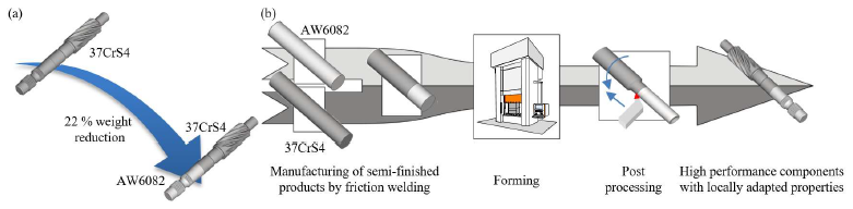
Fig. 1. (a) Weight reduction by using tailored forming, (b) Process chain for the manufacturing of hybrid pinion shafts
Fig. 1 (b) shows the tailored forming process chain for manufacturing the hybrid pinion shaft combining the steel alloy 37CrS4 and aluminium alloy AW6082, which enables a weight reduction of 22 % compared to the monomaterial-pinion shaft out of steel. In the production of tailored-formed components, the material-fit joining is carried out on semi-finished products with a simple geometric shape, which simplifies the handling as well as the process-reliable production of the joining zone. In this way, it is possible to manufacture components from different materials, which could not be produced previously due to their complex shape and the associated problems of joining. In addition, optimisation of the joining zone quality, or improved bonding of the combination of materials is made possible by thermomechanical treatment of the joining zone during forming. For this purpose, Behrens et al. investigated the mechanical properties of laser welded semi-finished products after an extrusion process [13]. It was shown that the forming process, on the one hand, significantly improved the microstructure in the joining zone and achieved consistent bond strengths.
The use of strongly differing material combinations for the production of highly stressable solid components demands a high level of all process steps in terms of manufacturing technology. This paper focuses on the challenges that must be overcome in the production of the hybrid pinion shaft made of aluminium and steel. In order to manufacture hybrid components with high process reliability, it is above all necessary to control the material flow by equalising the flow stresses. A greater difference in flow stress between the composite materials results in higher tensile stresses in the joining zone, which can lead to an early failure of the component. For this reason, a comprehensive material characterisation of the materials being used is carried out in order to define the suitable forming temperature range at which the two materials exhibit comparable flow stresses.
During the forging of hybrid aluminium-steel semi-finished products, homogeneous component heating can lead to the deformation capacity of the steel material being exceeded during the forming process. Furthermore, the maximum homogeneous heating temperature is limited by the melting temperature of the aluminium. Therefore, inhomogeneous heating of the hybrid semifinished product must be carried out to equalize the flow stresses.
3 Materials and methods
3.1 Investigation of suitable forming temperature ranges
Within the framework of subproject T02 of the CRC 1153, the chemical composition was first determined using a spectrometer from Spectro Analytical Instruments GmbH, see following Table 1.
Table 1. Chemical composition in wt % of 37CrS4 and AW6082 as determined by optical emission spectroscopy, only elements with a mass fraction above 0.05 % listed
|
Material |
C |
Si |
Fe |
Mn |
Cr |
Mg |
Al |
|
37CrS4 |
0.391 |
0.227 |
97.396 |
0.734 |
1.078 |
- |
- |
|
AW6082 |
- |
0.987 |
0.098 |
0.456 |
0.066 |
0.590 |
97.670 |
In addition, flow curves for the respective joining components at process-relevant forming temperatures and strain rates between 0.1 s-1 and 10 s-1 were determined using cylinder compression tests for the numerical process design. These experiments were carried out on the forming simulator Gleeble-3800 GTC. The resulting data from the testing machine were used to compute the coefficients for the analytical flow curve approach called Hensel-Spittel-10. Subsequently, the flow modelling was validated with the aid of numerical mapping of the cylinder compression tests. The force-displacement curves and the geometry of the workpieces after the cylinder compression test were used as validation criteria. In Fig. 2 the results of the determined flow curves for the steel alloy 37CrS4 and the aluminium alloy AW6082 at strain rates of 1 s-1 are exemplarily shown. The flow curves show a strong dependence of the yield stress on the forming temperature. As the forming temperature increases, the yield stress of the material decreases. Based on the flow curves determined, a suitable forming temperature range in which the joining components have comparable flow stress levels can be defined between 500 °C and 900 °C in the case of the steel alloy and between 20 °C and 300 °C in the case of the aluminium alloy. In this temperature range, it is possible to improve the properties of the joining zone by the thermomechanical process. Subsequently, the determined flow curves were implemented in the commercial FE-system simufact.forming 16.0.
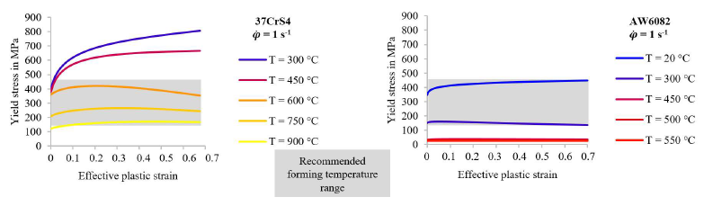 Fig. 2. Definition of suitable forming temperatures for the production of the hybrid pinion shaft
3.2 Production of steel-aluminium semi-finished components by friction welding
The hybrid semi-finished products were manufactured on the Genius Plus friction welding system from KUKA. Semi-finished products with a diameter of 30 mm and a length of 150 mm (AW6082) and 220 mm (37CrS4) were used for friction welding. For preparation of the initial billets, their end faces were face-turned and then an alcohol based cleaning material was applied to the welding surfaces. Main welding parameters for used welding surface geometries are given in the Table 2.
Table 2. Process parameters for friction welding of steel-aluminium billets
|
Welding surface geometry |
Billet diameter |
Axial shortening |
Rubbing pressure |
Forging time |
Forging pressure |
|
[°] |
[mm] |
[mm] |
[MPa] |
[s] |
[MPa] |
|
0 |
30 |
4 |
120 |
4 |
225 |
|
30 |
30 |
12.6 |
120 |
4 |
225 |
|
45 |
30 |
19 |
120 |
4 |
225 |
The semi-finished products to be joined were placed in the friction welding machine in a slide and spindle clamp. A rotational movement of the spindle and a translational displacement of the slide caused both semi-finished products to be strongly heated at the end faces due to the frictional heat. Both components were thus welded by breaking the rotating semi-finished product and pressing under an increased force of the stationary semi-finished product. The flow stress of aluminium is generally much lower as the flow stress of steel. Therefore, steel is not subjected to plastic deformation during the welding process, whilst aluminium is displaced to the welding flash from the rubbing zone. As a result of this process, the characteristic weld bead occurs at the joining zone which is mechanically removed afterwards. Fig. 3 shows the schematic representation of the different welding surface geometries of the 37CrS4 steel alloy, as well as the tensile specimens used to characterise the global and local bond strength.
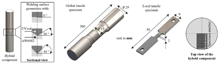
Fig. 3. Schematic representation of the various welding surface geometries of the 37CrS4 steel alloy and the specimen geometries for the determination of the global and local bonding strengths
In order to determine the critical stresses that lead to failure of the joining zone, the resulting joining zones were investigated analogously to previous work of the authors [14] by uniaxial tensile tests. The determination of the bond strength of the hybrid components with different welding surface geometries was initially carried out globally, i.e. the largest possible cross-section of the joining zone surface was tested by means of tensile tests. These tests were repeated five times. For this purpose, the global tensile specimens were prepared from the semi-finished products by machining (see Fig. 3). To evaluate the influence of the conical weld surface geometries locally, flat tensile specimens were subsequently prepared and characterised from the cross-section of the semi-finished products. Therefore, six small flat tensile specimens (specimen number 1 to 6) were prepared analogously to the method described in [14] by wire erosion every 2 mm along the cross-section of the hybrid semi-finished products, as sketched in Fig. 3. With the help of the chosen small specimen geometry, it was possible to evaluate the entire joining zone area locally. These tests were repeated five times for each of the hybrid components.
4 Results
4.1 Evaluation of the bond strength of steel-aluminium semi-finished products
In Fig. 4 the results of the global and local tensile tests are presented. The error bars represent the min/max values from the five repetition tests. As described in [5, 6], a positive influence of the weld surface geometries on the bond strength could also be observed with the used material combination 37CrS4 and AW6082. Comparing the results in Fig. 4 (a) between 0° and 45°, a bond strength of around 245 MPa can be determined for both weld surface geometries. However, in the case of 45°, a significant decrease in maximum and minimum values could be observed. The maximum deviation for the weld surface geometry 0° was 54.6 MPa, whereas a significantly lower maximum deviation of 1.75 MPa was determined for 45°. This influence was also determined in the local bond strength tests. The aim of the conical weld surface geometry was to increase the relative velocity in the center of the semi-finished product during friction welding. The intention was to increase the cohesive bond and thus the bond strength of the semi-finished components being verified with the aid of local bond strength tests. In contrast to the 0° weld surface geometry, the bond strength of the 45° weld surface geometry increases from specimen 6 (average bond strength of 236.99 MPa) to the center. Only specimen 1, which has no relative velocity during the friction welding process, shows low bond strengths of 228.96 MPa with a large maximum deviation of 58.24 MPa. The bond strengths of the 0° weld surface geometries decrease significantly from specimen 5 (199.03 MPa) to the center (141.42 MPa) of the semi-finished product.
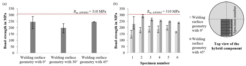
Fig. 4. (a) Determination of the global bond strengths for various welding surface geometries of the steel alloy, (b) Determination of the local bond strengths for welding surface geometries 0° and 45° of the steel alloy (the error bars represent the min/max values of five tests)
4.2 Induction heating
A schematic representation of the induction heating system with highlighted positions of the thermocouples (TC) is shown in Fig. 5 (a). The resulting temperatures were determined with the help of six TC in order to subsequently validate the numerical heating simulations. TC1 was fixed in the center of the aluminium alloy 20 mm away from the joining zone. All other TC were fixed on the surface of the semi-finished product. TC2 and TC3 were fixed 2.5 mm, TC4 15 mm and TC5 30 mm away from the joining zone. The numerical results show good agreement with the experimentally determined semi-finished workpiece temperature. Fig. 5 (b) shows exemplary results for the weld surface geometries 0° and 45°. The inhomogeneous temperature distribution after 30 s was used as a starting value for the numerical tool analysis in the next chapter.
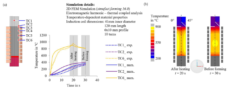
Fig. 5. (a) Schematic setup of the experimental induction heating with the thermocouples used, (b) Temperature distributions of the numerical heating simulations for the weld surface geometries 0° and 45°
4.3 Numerical extrusion process design
In Fig. 6 the FE-model of the numerical process design is presented. The extrusion process studied is a rotationally symmetrical forming process and was therefore modeled in 2D. After 20 s of induction heating, the semi-finished product is transferred to the tooling system within 10 s. During the transport, the semi-finished product is also rotated by 180° and is placed in the die with the aluminium side. Subsequently, the forming takes place within 0.169 s.
In the following, the results for the tool design, which is modeled with the commercial FE-system simufact.forming 16.0 taking into account the previously described material data and the respective inhomogeneous temperature distributions from Fig. 5 (b), are presented.
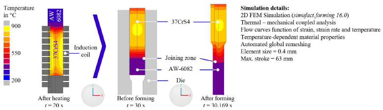 Fig. 6. Joining zone design and temperature distribution at the end of the extrusion process for steel-aluminium combinations
The main goal of the work was to design a die geometry in which the resulting tensile stresses during forming of the hybrid pinion shaft are as low as possible. For this purpose, various die geometries were designed in the first step, which varied in their die opening angles. Die opening angles (2α) between 60° and 120° were considered. These investigations were carried out with the 0° and 45° weld surface geometries. To evaluate the results, the effective plastic strain rates and the first principal stresses were used. Fig. 7 shows exemplary the influence of the respective angles on the effective plastic strain rates and the first principal stresses for the weld surface geometry 0°. For the weld surface geometries 30° and 45°, the same influence could be determined.
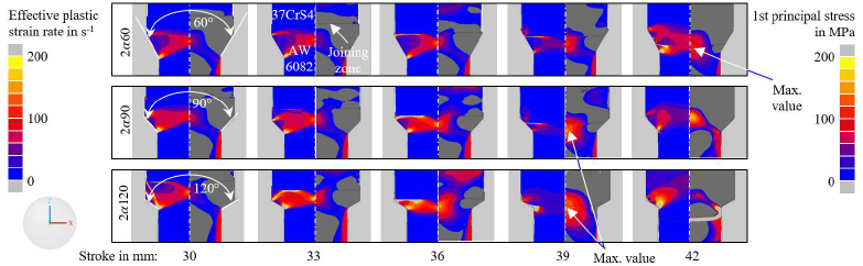
Fig. 7. Influence of the die geometries on the effective plastic strain rate and the first principal stress for the weld surface geometry 0°. The scale of the legends has been adjusted accordingly and does not correspond to the maximum values.
The investigations have shown that the first principal stresses occurring in the semi-finished product during forming are lowest for the 2α60 die geometry. To reduce the resulting tensile stresses in the joining zone even further, the die geometry was varied regarding the radii in the area of the taper. In Fig. 8 (a) the comparison of the effective plastic strain rate and the first principal stresses between dies 2α60 and a modified die (2α60_mod) with a radius of 20 mm in the area of the taper are shown. It can be seen, that these modification leads to a further reduction the first principal stress as expected. These investigations were also carried out with the weld surface geometries of 30° and 45°. Figure 8 (b) shows the effective plastic strain rate and the first principal stress for the modified die geometry with the 45° weld surface geometry. Significantly higher tensile stresses were determined here in the area of the joining zone.
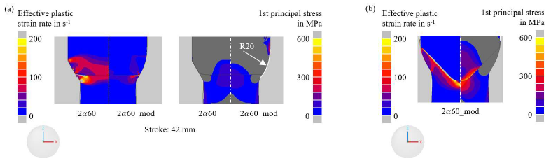
Fig. 8. (a) Comparison between 2α60 and the modified die geometry by adjusting the die radius, (b) Influence of the modified die on the effective plastic strain rate and the first principal stress for the weld surface geometry 45°
5 Summary and outlook
Within the scope of this work, a numerical die design was carried out, taking into account various semi-finished product geometries. The aim was to identify a die geometry which leads to the lowest tensile stresses in the area of the joining zone during forming. For this purpose, the material model has been validated. A validation of the FE-model will be carried out with the results of the experimental forming tests.
By modifying the die geometry, the resulting first principal stresses in the joining zone of the shaft have been reduced. With increasing stresses in the joining zone, the probability of failure of the hybrid component rises significantly. Nevertheless, the resulting first principal stresses for the weld surface geometries with angles of 30° and 45° are significantly greater than for an angle of for 0°. One reason for this could be that the steel material undergoes hardly any deformation in the area of the joining zone and the effective plastic strain rate is very low. On the other hand, the aluminium is both strongly deformed and accelerated in the area of the joining zone resulting in a large velocity gradient and high stresses in the joining zone between the two materials.
As a next step, the experimentally determined local bond strengths will be implemented into the commercial FE software simufact.forming 16.0. This will allow for a numerical prediction which joining zone geometry (weld surface geometry) will withstand the forming loads during the forming process. In addition, the modified die geometries are manufactured and subsequently experimental forging tests are to be carried out. The results of the experimental forging tests will be used to validate the numerical results.
Acknowledgements
The results presented in this paper were obtained within the Collaborative Research Centre 1153 “Process chain to produce hybrid high performance components by Tailored Forming” in the subproject T02 – 252662854. The authors would like to thank the German Research Foundation (DFG) for the financial and organisational support of this project.
