1 Introduction
In order to achieve the new emission limits negotiated by the European Union in 2020 [1], the automotive industry will continue to focus on lightweight constructions to meet the limit values. Additionally, novel full autonomic vehicles play a central role in the mobility of the future, there more sensor systems will increase the weight of the vehicle. Both challenges influence future designs and change the overall structure of vehicles and their weight. Hybrid components open up the possibility to design application-optimised parts with a high lightweight potential combining individual benefits of different materials in one component. The manufacturing of hybrid components by bulk metal forming represents a promising method to produce near-net-shape functional components with complex geometries and outstanding mechanical properties within just a few processing steps [2]. An innovative manufacturing route for the production of hybrid components is investigated within the Collaborative Research Centre (CRC) 1153 Tailored Forming at the Leibniz University of Hanover. The main objective within the CRC is the use of pre-joined semi-finished hybrid goods, which allows for efficient hybrid part production. Further advantages are the design and realisation of complex load-adjusted joining zone shapes and a process integrated thermo-mechanical treatment of the joining zone. The overall Tailored Forming process chain is schematically depicted in Fig. 1 [2]. However, to achieve equivalent flow properties in a steel-aluminium combination, an inhomogeneous temperature distribution within the hybrid semi-finished product is required. The induction heating process is suited for the heating of serially arranged hybrid semi-finished products because it enables a rapid localized heating of the steel whereby the aluminium section is heated indirectly by means of thermal conduction [3]. Induction heating relies on the physical effect of eddy currents, which cause a heating of the workpiece according to Joule’s law. The process is influenced by the electromagnetic material properties of the heated material, especially the electrical resistivity and the relative magnetic permeability. This is the ability of a material to conduct the magnetic flux better or worse than a vacuum [4]. The determination of that material parameter strongly influences the outcome of a numerical simulation of an induction heating process [5]. All plain carbon steels and many alloy steels are ferromagnetic and thus have a high relative magnetic permeability μr >> 1 [6]. Zedler [7] presents an inverse method for the determination of the relative permeability for low alloyed steels. Di Barba, Mognaschi et al. [8] investigated the influence of different modelling approaches for the relative permeability on simulations of induction heating of steel billets.
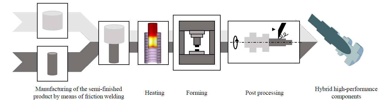
Fig. 1. Tailored Forming process chain consisting of manufacturing of the hybrid semi-finished product, induction heating, forming, post processing [2]
In this study, a numerical model of an induction heating process of a cylindrical semi-finished product of 1.3505 (100Cr6) was set up for validating the presented inverse material determination method of the relative magnetic permeability. In addition, the induction heating process of hybrid semi-finished product consisting of 1.7147 (20MnCr5) and aluminium alloy 3.2315 (EN-AW-6082) was developed to investigate the resulting temperature distribution after the induction heating process. Furthermore, the influence of the resulting temperature distribution on the material distribution within a numerical impact extrusion process of the pre joined semi-finished hybrid good was investigated.
2 Method
2.1 Determination of the relative magnetic permeability
The inverse method proposed by Zedler [7] is applied to determine the relative permeability of the low-alloy steel 1.3505 and the case-hardening steel 1.7147. The relative magnetic permeability μr is given by equation 1, which is a function depending on the temperature T that was proposed by Nacke [9].

In a pre-step, a numerical investigation was carried out to determine the maximum magnetic field intensity that can be achieved in the current setup with 1.3505 and 1.7147. With the results, the relative magnetic permeability was determined from the diagram in Fig. 2. (a) and was set as μr20 of equation 1 according to the carbon content of the material.
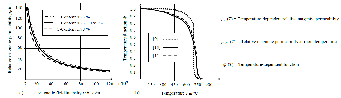
Fig. 2. (a) Dependency of the relative permeability on magnetic field intensity H in A/m and (b) Temperature function according to three different approaches
Then different temperature-dependent functions φ(T) were tested and integrated to fulfil equation 1. The dotted line was given in [9]. In [10] the solid line was published and finally the dashed line was taken from [11]. Since 1.3505 is a low alloy steel, it is suitable to estimate the relative magnetic permeability μr based on the described inverse method of Zedler [7]. For 1.7147 the assumption of a low alloy cannot be fulfilled and the results of the numerical simulation must be read with caution. The results of the material characterisation are discussed in chapter 3.1.
2.2 Experimental induction heating with the mono-material billet of 1.3505
The used experimental setup is shown in Fig. 3. (a). A mono-material billet is placed inside a water-cooled induction coil, which consists of coiled circular copper tubes with a diameter of 8 mm and a wall thickness of 1 mm. The height of the induction structure sums up to 81 mm with eight windings and an inner diameter of 51 mm (cf. Fig.3. (b)). It is linked to a generator (TRUMPF TruHeat MF 3040) with a maximum output current of 111.6 A, a voltage of 430 V and power of 44 kW. The used current intensity time curve is presented in Fig. 4. (a). The current in the induction coil during the process was measured using a Rogowski coil (FLUKE I3000S FLEX-24) which was placed around one supply line of the induction coil. The generator power was recorded during the experimental tests. A mono-material billet of 1.3505 with a height of 35 mm and a diameter of 30 mm was used. Furthermore, five thermocouples of type K were used to measure the temperature and were placed on the billet according to Fig. 3. (c).
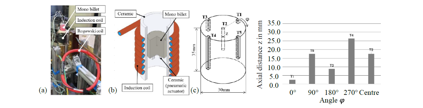
Fig. 3. a) Position of the Rogowski coil for the measurement of the induction current, (b) structure of the experimental induction test setup and (c) Distribution of the thermocouples on the surface area of the cylindrical specimen with the different heights depicted in the table
2.3 Numerical investigation of the induction heating processes
An axisymmetric simulation model of the induction heating process based on the experimental test was set up using the simulation software Simufact Forming v16. The model is depicted in Fig. 4 (a). There are three parts in this model. One is the surrounding air in the process. It is divided into the three areas called inner-, outer- and far field. While the inner-field represents the surrounding air of the coil and the workpiece, the far-field is necessary to set the boundary conditions of the electromagnetic analysis. The outer-field bridges the area between the inner and far-field and is meshed coarse to reduce the calculation time.
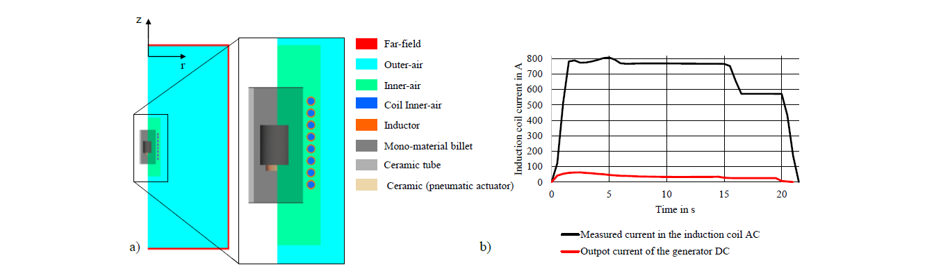
Fig. 4. (a) Numerical model of the induction process of the mono-material specimen and (b) Output current of the generator and measured current in the induction coil as input parameter for the numerical induction heating simulation
The next part is the induction coil. Each winding of the coil is represented in the model by an inductance object to which the operating frequency of 18.3 kHz and the current-time curve experimental measured in the induction coil as well as the cross-sectional geometry of the wound wire have been assigned. The measured current-time-curve is shown in Fig. 4 (b).
The last part is the billet, which modelled as an ideal cylinder of 1.3505. The temperature dependent relative magnetic permeability was calculated as described in section 2.1. The initial temperature of the billet was set to 30 °C and a convection coefficient of 50 W/m²K was assigned. The ceramic components were added to the simulation model as heat conductive bodies and the material properties were taken from literature [12]. The presented model is used to validate the inverse method of Zedler by comparing experimental and numerical heating test.
To investigate the heating behaviour of a hybrid semi-finished product a numerical model for the induction heating of the hybrid semi-finished product was developed based on the experimental setup from the work of Behrens, Goldstein et al. [13]. The setup consists of a hybrid billet consisting of 1.7147 and 3.2315, which was placed in the inside of an induction coil. The hybrid billet was moved with an axial offset within the coil, so that the joining zone of the hybrid billet was positioned at the level of the upper winding of the coil. The hybrid semi-finished product had a total height of 100 mm and a diameter of 40 mm and was modelled out of two sections with a height of 40 mm (3.2315) and 60 mm (1.7147). Between these sections, an adhesive contact was defined to achieve an ideal thermal contact. Between the two sections, an intermetallic layer of 0.07 μm was assumed with a thermal conductivity of 10 W/mK [13]. The thermal material properties of 3.2315 and 1.7147 were obtained from the Simufact Forming database. The relative magnetic permeability of 1.7147 was calculated as described in section 2.1. The number of turns of the induction coil was increased to eleven due to the size of the hybrid specimen. Additionally, the ceramic parts and the copper shunt (Cu-ETP) were added to the numerical model and the properties are shown in table 1. To approximate the current in the induction coil during the heating of the hybrid billet, the output current from the generator that was given by [13] was scaled up by the ratio of generator and induction coil current of the mono-material billet test. Due the increase of the amount windings, the real current in the induction coil differs. The result is shown in Fig. 5. (a). The operating frequency was also given in the output data from the generator and was set to 13.9 kHz. The heating of the hybrid billet took 20 seconds.
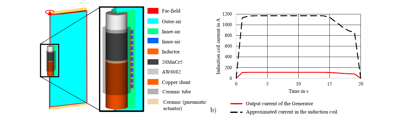
Fig. 5. (a) Numerical model of the induction process of the mono-material specimen and (b) Output current of the generator and current in the induction coil as input parameters for the numerical induction heating simulation
Table 1: Material properties of Ceramic [12] and Cu-ETP [14]
![Table 1: Material properties of Ceramic [12] and Cu-ETP [14]](docannexe/image/574/img-7.png)
2.4 Numerical modelling of the impact extrusion process
The coupled numerical model consisting of the induction heating process from chapter 2.3 and the impact extrusion process is presented in Fig. 6. A detailed description of the model of the impact extrusion process is given in [15]. The flow properties of the hybrid semi-finished product were taken from [16]. The initial temperature of the semi-finished product was imported from the simulation of the induction heating process. This numerical simulation of impact extrusion process has been carried out using the calculated temperature distribution from induction heating simulations described in section 3.3 as well as under consideration of a homogenous temperature distribution to observe the resulting material flow and especially the final form of the joining zone.
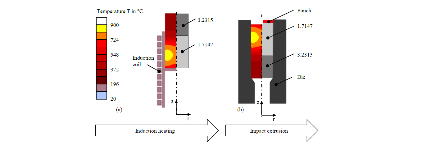
Fig. 6. Coupled numerical process chain consisting of (a) induction heating process and (b) impact extrusion forming process
3 Results
3.1 Results of the material characterisation
Based on the pre-step simulation a maximum magnetic field of 14000 A/m for 1.3505 and of 16000 A/m for 1.7147 was achieved. These values were set as μr20. By combining these values with the temperature dependent function φ(T) according to [10], equation 1 is fully described. The calculated relative magnetic permeability μr (T) for 1.3505 is depicted in Fig. 7. The used inverse method shows nearly no difference of the relative magnetic permeability between the materials 1.3505 and 1.7147. The Currie temperature Tc is reached around 710°C, which causes the loss of the magnetic properties of the heated ferromagnetic steel and leads to a sudden decline of the relative magnetic permeability [6].
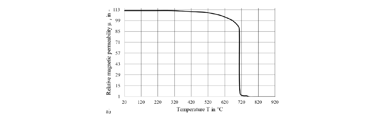
Fig. 7. Calculated relative magnetic permeability according to the method of Zedler [7]
3.2 Experimental and numerical results of the induction heating tests of the mono-material specimen of 1.3505
The resulting temperature-time diagram of induction heating tests with 1.3505 for three selected thermocouples (TC3, TC4 and TC5) is depicted in Fig. 8. The black line depicts the results of the experimental heating tests. The dashed red line represents the numerical results using the temperature dependent relative magnetic permeability caclulated in 3.1. The experimental and numerical temperature-time diagrams show a very good agreement. The grey dotted line shows the numerically temperature-time-curve, which was numerically calculated using the data of the relative magnetic permeability from the Simufact Forming database. The results indicate that data from the Simufact Forming database are not suitable for the numerical investigation of an induction heating process with 1.3505. Overall, the presented results show that the developed numerical model combined with the calculated relative magnetic permeability according to the method of Zedler is suitable for the numerical calculation of an induction heating process of 1.3505.
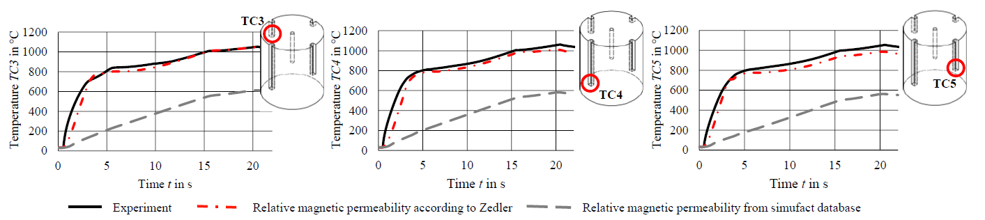
Fig. 8. Results of the experimental induction heating test of the mono-material specimen and the comparison with the results of the numerical induction heating generated with the material data according to Zedler and the Simufact Forming database
3.3 Experimental and numerical results of the induction heating tests of the hybrid specimen
Fig. 9 shows the results of the numerical and experimental induction heating process of the hybrid semi-finished product. The relative magnetic permeability of 1.7147 from chapter 3.1 was used in the numerical induction heating model. First, the overall comparison of the selected thermocouples TCH1, TCH2 and TCH6 show a good agreement of the experimental and numerical results. The thermocouples TCH2 and TCH1 represent the temperature in the aluminium section. The good agreement of numerical and experimental results indicates that the modelling of the thermal heat conduction from the steel section through the intermetallic phase to the aluminium section is an appropriate approach. Thermocouple TCH6 represents the results in the steel section. The experimental and numerical results are in good agreement here, as well. Therefore, the calculation of the relative magnetic permeability according to Zedler [7] is also suitable for the steel alloy 1.7147. However, the numerical and experimental results in Fig. 9 differ stronger than in the investigation with 1.3505, which can be explained by the calculated input current. A measurement of the induction current provides more accurate values for the numerical investigation.
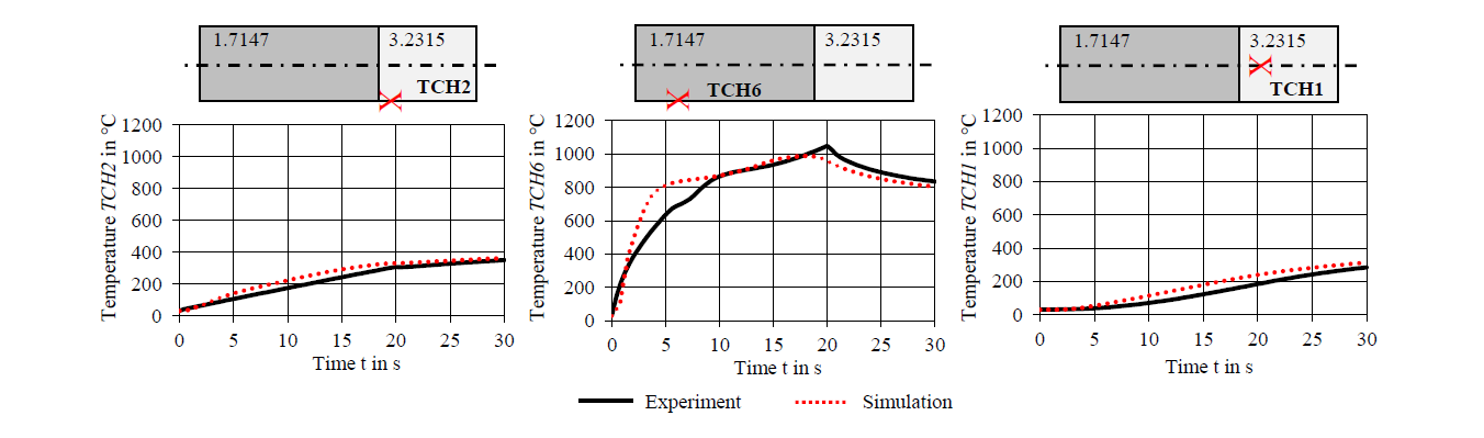
Fig. 9. Comparison of the results of the experimental induction heating test of the hybrid specimen and the comparison with the results of the numerical induction heating generated with the material data according to Zedler
3.4 Numerical results of the impact extrusion test with a hybrid semi-finished product
The comparison of the results presented in Fig. 10 shows a strong influence of predicted temperature distribution on the joining zone shape. It can be observed that the resulting deformation of the joining zone can be predicted more accurately if the temperature distribution was taken from numerical simulation of induction heating process. In comparison, Fig. 10 (c) shows the deformed joining zone, which was numerical predicted under consideration of a homogeneous temperature distribution in each material sections. The initial temperature in the steel section was 1250 °C and respectively 450 °C in the aluminium section. In consequence, a coupled process simulation consisting of inductive heating and forming simulation can predict process parameters in the forming stage more exactly. This can help to avoid process failure like a cracking of the joining zone due to high tensile stresses, which can occur at unfavourable temperature control during the forming of hybrid semi-finished products. The numerical simulation of an induction heating process will be advantageous in the development process of hybrid components manufactured by means of the Tailored Forming process chain.
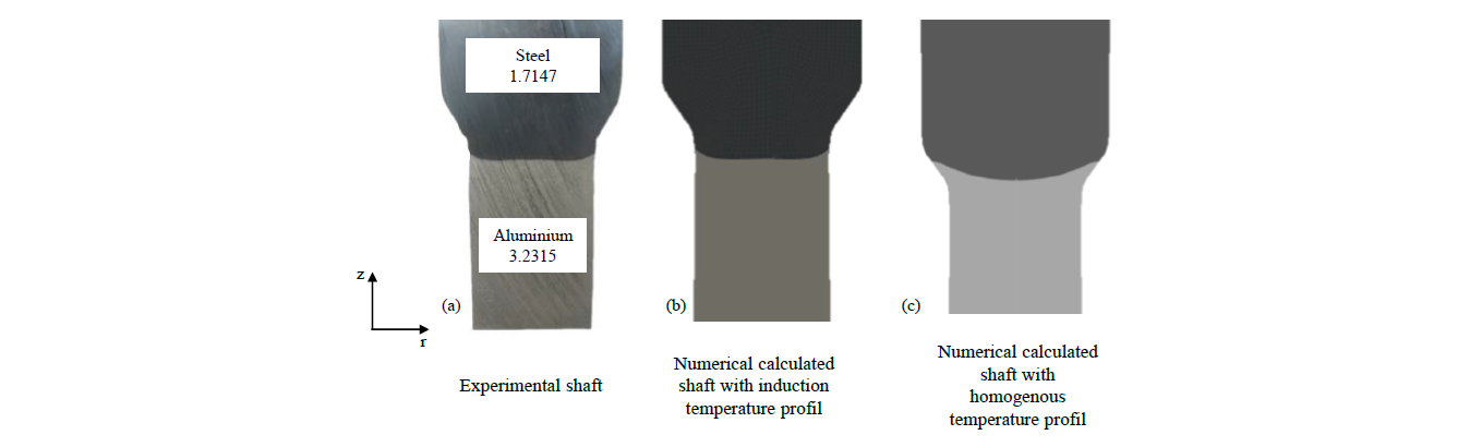
Fig. 10. Comparison of the material flow based on a sectional view of an experimental and a numerical hybrid shaft after the forming process, (a) experimental, (b) with induction heating temperature profile, (c) with homogenous heating profile in each material section
4 Conclusions and outlook
In the presented work, the relative magnetic permeability as a function of temperature was calculated by an inverse method for the low alloy steel 1.3505 and case-hardened steel 1.7147. A numerical model of an induction heating process for a cylindrical sample was set up with Simufact Forming. In addition, experimental heating tests were carried out with an induction unit. The resulting temperature-time-diagrams of the experimental tests were compared with the numerical results and show a very good agreement when using the relative magnetic permeability generated by the Zedler. An investigation of induction heating and subsequent impact extrusion using a serially arranged hybrid semi-finished product consisting of steel 1.7147 and aluminium 3.2315 was carried out. The temperature-time diagrams of the experimental and numerical results were in good agreement. The results of the coupled simulation of a hybrid shaft show a good agreement of the final shape of the joining zone compared to an experimental section view of a hybrid shaft. In future work, the dependence of the relative magnetic permeability will be extended by that of the magnetic field strength by means of a user subroutine. This should further improve numerical inductive heating and make it applicable for other materials. The presented numerical model of induction heating can be used for other hybrid products such as a bevel gear or a bearing bush, which are manufactured using the Tailored Forming process chain in order to predict the material flow within the forming stage more precisely.
Acknowledgements
The results presented in this paper were obtained within the Collaborative Research Centre 1153 “Process chain to produce hybrid high-performance components by Tailored Forming” in the subproject C1. The authors would like to thank the German Research Foundation (German Research Foundation, DFG, 252662854) for the financial and organisational support of this project.
