1 Introduction
Increasing the service life of forging tools improves the economic efficiency of forging production. The replacement of a defect tool is connected with production loss, production interruptions as well as costs for new tools, and therefore has to be avoided as long as possible. Generally, forging tools are subject to a superimposed cyclic load spectrum. The stress type and its effect on the forging tool depends on many factors like the engraving geometry, the contact condition, the workpiece temperature and the material flow [1]. Due to the notch effect in narrow radii and the resulting high mechanically induced stresses, crack formation and propagation is a typical tool failure, shown in Fig. 1. Due to high cyclical loads, the forging die is subjected to high normal and shear stresses. This results in micro-deformations and clusterig of dislocations at grain boundaries and inclusions, followed by near-surface crack formation, which propagates with each forging cycle [2]. The number of load bearing cycles is decisive for the efficiency of a forging process and defines the tool’s service life [3].
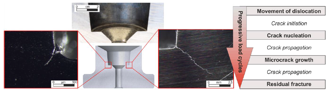 Fig. 1. Defect lower die with critical failure due to mechanical load (left) and crack stages (right).
The tool life also affects the quality of the forgings, as the damaged dies and stamps cause a change in the geometry of the manufactured product, and any surface faults are represented on the forged product as imprint. [4] The increase in hardness of conventional hot working steels, without loss of ductile properties, is limited in conventional thermal tempering processes. These properties (hardness and ductility) are crucial to counteract the described failure due to crack formation under high thermo-mechanical loads. Among the thermo-mechanical treatment processes, ausforming shows a high potential to produce steels with both, high ductility and hardness. The combination of grain refinement and microstructural texturing should lead to an increase in service life of the ausformed part. Ausforming is a method of improving the above-mentioned properties by adapting the microstructure alignment (texture) to the actual load while simultaneously refining the grains [5]. During ausforming, the deformed texture in the metastable austenite phase is transferred to the martensitic microstructure in a preceding quenching treatment. The lattice defects introduced by the deformation affect the solubility, the diffusion of foreign atoms, self-diffusion and thus the nucleation and growth of the phase during its allotropic transformation. By exploiting this effect, it is possible to achieve material properties that cannot be reached by conventional methods [6].
The aim of this study is to increase the service life of forging tools by improving the microstructural properties of hot working steels with regard to ductility and hardness. Cups from tool steel X37CrMoV5-1 (AISI H11) were ausformed under variation of the true plastic strain. Subsequently, pulsation tests were carried out to investigate the material behavior under operating conditions of alternating mechanical loads.
In previous studies [7] bolts of X37CrMoV5-1 (AISI H11) which were ausformed via full forward extrusion with a subsequent applied tempering treatment at 500 °C were investigated. Here, mainly cracks occurred in the head area of the manufactured bolts. It is described that anisotropic behaviour is established by an introduced texturing and the grain is deformed but not refined, what caused these cracks [7]. The ausforming performance potential was not exploited, since the adjustment of the forming temperature by partial cooling in connection with lower true plastic strains show a possibility to maintain ductility.
Therefore, the authors investigated the ausforming process by means of upsetting tests in the metastable austenite phase and thus lower forming temperature in preliminary studies [8]. It could be shown that a longer holding time turns out to shift higher hardness values towards the center. The deformation introduced into the material has an influence on the attainable hardness. At φ = 0.45, higher hardness values are achieved than at φ = 0.25, but also show the occurrence of cracks. There must be a compromise between the required hardness and the ductility to be maintained without exceeding the critical forming parameters.
2 Method
For service life testing of ausformed die inserts, cups are produced with the same engraving geometry as the die inserts to be manufactured later. For this purpose, preforms are first created which are formed with the die set shown in Fig. 2 and the bottom thickness of 9 mm and 11 mm. The bottom thickness is decisive for the global true plastic strain while ausforming and for the material flow that occurs during forming process in the metastable austenite range. The preformed workpieces were made of hot-working tool steel X37CrMoV5-1 (AISI H11) by die forging at 1060 °C above Ac3-temperature. This steel grade contains austenite stabilizing elements such as Cr, Mo, V and is particularly suitable for the ausforming process due to its slower transformation kinetics in the austenite phase [8]. The forging tools were also made of X37CrMoV5-1 (AISI H11) and were lubricated with Con Traer G 300 which was applied on the tools before positioning the warm preforms. For the tests, the samples were austenitised for 10 minutes in a batch furnace at 1060 °C, then cooled to the temperature area of metastable austenite (500 - 600 °C) above the martensite start temperature Ms and finally ausformed with a global true plastic strain of φ = 0.25 (9 mm initial height) or φ = 0.45 (11 mm initial height). For cooling into the metastable austenite range, water is used as a cooling medium, which is sprayed onto the surface to be formed and thus leads to an increased yield stress of the material in the near-surface area while cooling. The temperature at the workpiece surface is monitored by means of a thermal imaging camera, since undercooling can lead to premature phase transformation of the material and consequently to failure due to cracking [8]. However, it is not possible to cool the entire forging to a forming temperature, since other material areas are not actively cooled and heat is only extracted by tool contact. The cooling water is applied with a GERLIEVA membrane spray head. Preliminary tests have already shown suitable pressure parameters for producing a uniform conical spray pattern with a controllable cooling rate. Spray parameters from preliminary tests [8] are used to prevent damage during forming. As soon as the forming temperature on the surface is reached, the preforms were ausformed using a screw press Lasco SPR 500 and then quenched in water to room temperature.
After forming, forgings show high brittleness. Tempering causes the diffusion of carbon atoms, as a result of which internal stresses are relieved. At tempering temperatures around 500 °C, a secondary hardening effect occurs due to dispersion hardening. Finely dispersed carbide precipitates have a slip-blocking effect, so that hardness and strength increase [9]. This effect can even be increased with increasing true plastic strain [10]. To investigate the influence of tempering after ausforming on the mechanical load resistance the cups were tempered at 300 °C and 500 °C. In order to obtain specimens from the cups produced in this way, wire cut EDM was chosen. After eroding, the specimens were examined for material failure and hardness measurements were carried out.
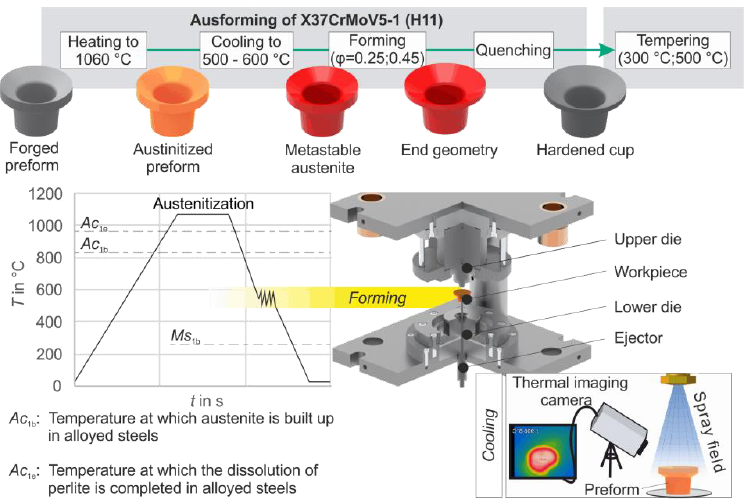 Fig. 2. Forging tools and ausforming process
To investigate the mechanical fatigue resistance, tests were carried out with the RUMUL Testronic 150 kN fatigue testing machine at room temperature. These test intended an application-oriented characterization of the specimen, without taking abrasion, thermal and chemical load into account. The testing machine can apply dynamic and static loads. The dynamic drive consists of a main mass, a counter mass, the elasticity of the specimen and the oscillation generator system. The total vibration frequency results from the natural frequencies of the components connected in series. The preparation of the specimen and the experimental setup is shown in Fig. 3. For the test, 5 mm wide strips were eroded from the centre of the formed cups. These specimens were clamped in a fixture that adopts the geometry of the specimen and guides the static and dynamic tensile force of the pulsator into it. They represent the stadium of highest stress to the die engraving while forming. The cyclic application of the dynamic force FN,dyn allows an partial representation of the mechanical load in forming processes and an economic testing method without high energy and material loss. The high frequency of the applied fatigue also reduces the required testing time. The specimens were subjected to cyclic swelling load until fracture.
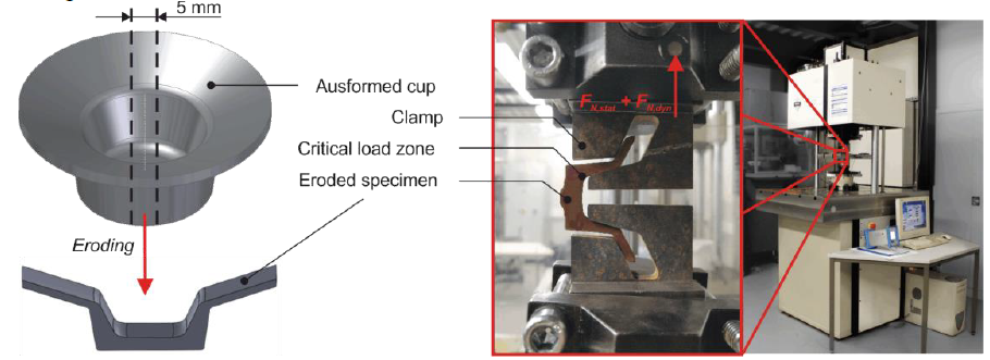 Fig. 3. Section of the eroded specimen and holding device for the fatigue test.
3 Results
First, static load limits were investigated on the eroded specimens, which occurred at an average tensile force FN,stat of 7.75 kN. Here, the failure point was located centrally in the bottom area of the specimens. With an applied oscillation of the dynamic force FN,dyn the applied bending stress in the radius of the contour causes the specimens to fail. Fig. 4 shows the number of load cycles endured in dependence of the true plastic strain during ausforming, the tempering temperature and the cyclic load amplitude. To provide statistical validation, 5 samples were analysed for each test series. The comparison of the number of cycles at different true plastic strains shows that test series with a smaller deformation endured a larger number of cycles. High standard deviations are evident. Furthermore, the number of load cycles decreases with higher amplitude of the dynamic force. Under the amplitude of 1500 N and the tempering temperature of 300 °C, the test series with φ = 0.25 and φ = 0.45 show a difference in the number of oscillations of 10.9 %. This difference increases to 21 % with higher amplitude of 2000 N.
With different tempering temperatures, a large difference in the number of load cycles endured can be seen. Under the same dynamic load, specimens tempered at 300 °C exhibit higher endurance. For specimen formed at φ = 0.25 and tested with 1500 N cyclic load, there is a cycle number difference of 52.8 % comparing the tempering temperatures. At higher load, this disparity drops to 6.4 %. A comparable behaviour is shown by the specimens with φ = 0.45 and different tempering treatment. Under the amplitude of 1500 N, a difference of 55.8 % in the endured cycle number is found. When the dynamic load is increased, the value decreases to 17.8 %.
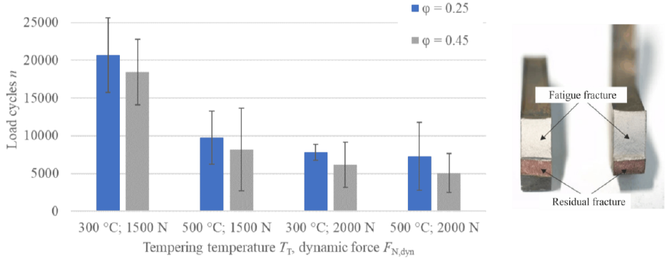 Fig. 4. Endured load cycles with standard deviation depending on tempering temperature and tensile force FN,dyn (left) and fractured surfaces (right)
Fig. 5 shows the hardness measurements on specimens with φ = 0.25 and φ = 0.45, taken from specimen tempered at 300 °C compared to the hardness of conventionally quenched and tempered material. It shows hardness profiles of the bottom and radius area of the specimen. The hardness decreases with greater distance to the edge. The measured values in the radius surface area (section A) of the specimens formed with φ = 0.45 are slightly above those of the specimen formed with φ = 0.25. The hardness values in the radius are increasing towards the surface. The lowest hardness value was measured in the centre of the cross-section. Towards the surface of the centre, the hardness decreases on both sides. The hardness profile of the specimen with φ = 0.25 shows very low hardness close to the surface.
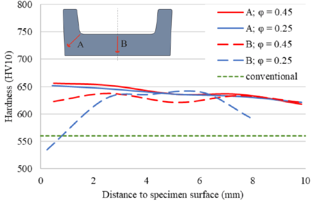 Fig. 5. Hardness profiles of the inner radius and specimen centre
The different martensite structures via ausforming and tempering in the radius and centre area of an ausformed part are displayed in Fig. 6. In the formed area, densified grain structures with defined grain boundaries can be seen. Here, the occurrence of microcracks can´t be detected. Furthermore, different martensite structures occurred in the radius and in the centre of the bottom region. The centre region shows no material flow during forming, leaving the martensite structure similar to that of a simply tempered material [8].
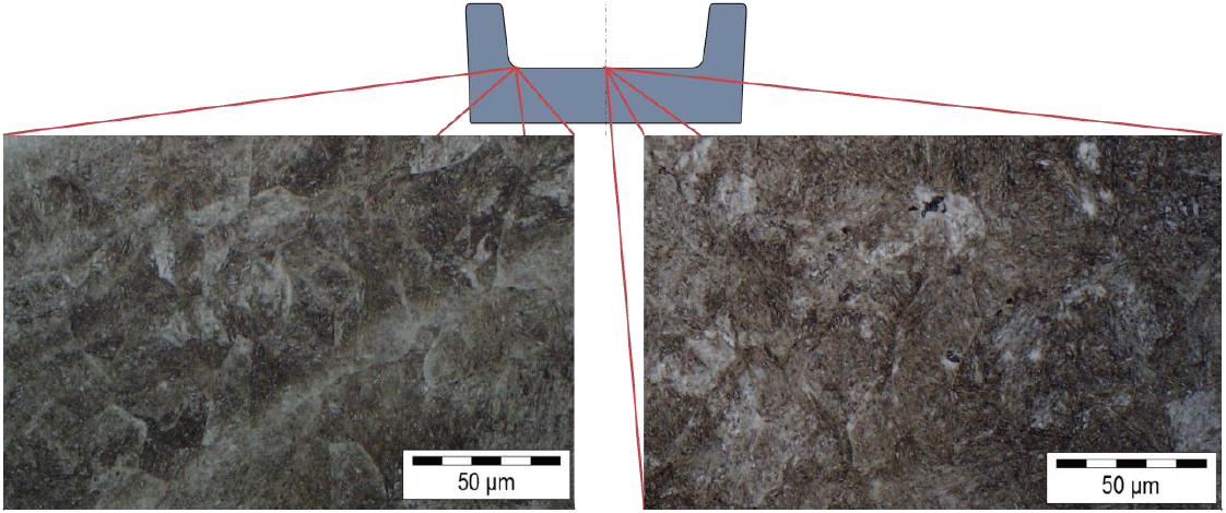 Fig. 6. Structures via ausforming and tempering in the radius and centre area of a specimen formed with φ = 0.25
4 Discussion
The fatigue tests have shown that higher fatigue life is achieved with lower deformation during ausforming. The difference in fatigue life between the different deformed specimens increases with higher amplitudes during testing. The higher true plastic strain causes greater ausforming of the material. The resulting lattice defects counteract a longer service life and promote crack propagation. In the radius area, higher number of lattice defects seem to serve not only as nuclei for martensite but also for local crack formation while exposure to a cyclic swelling load.
From the tempering diagram, the range of hardness values for 300 °C is 560 HV10. Ausforming achieves a hardness increase of 16 % compared with conventionally quenched and tempered specimens. In conjunction with the tempering temperature of 300 °C and φ = 0.25 forming, the highest number of oscillations could be achieved. Due to the high standard deviations, no significant difference between φ = 0.25 and φ = 0.45 can be determined. Test series tempered at 500 °C failed earlier. The reason for the lower fatigue life at higher tempering temperature may be the effect of secondary hardness. It can be considered that precipitation processes take place in the material, which increase hardness and strength by hindering dislocation movements. At the same time, toughness and ductility decrease. This effect does not occur at 300 °C tempering temperature.
The formation of martensite at an early stage during cooling to the forming temperature can influence the mechanical properties, since cracks can be initiated on the surface layer in a high-strength grain structures. Microcrack growth couldn´t be detected on the micrographs.
The differences in hardness between the specimen radius and the centre results from the different true plastic strain and material flow. While ausforming, the bottom centre of the inner contour is slightly deformed. This causes only a small number of lattice defects to be inherited by the martensite phase. Its microstructure is dark colored by the martensite needles and resembles that of a quenched and tempered specimen. It can be assumed that the effect of ausforming is not effective or only slightly effective in these areas, since the measured hardness value match to only quenched and tempered specimen [8]. In addition, edge decarburization occurred as a result of austenitization in ambient atmosphere. The surface generation in the radius area seems to eliminate the effect of edge decarburization occurring while heating.
5 Conclusion
In this study, the fatigue life of cyclically loaded ausformed specimens of X38CrMoV5-1 was investigated. After the preparation of the preform, ausforming was carried out. For this purpose, based on the investigations carried out, the process variables during forming with φ = 0.25 and tempering at 300 °C were considered suitable. The material gains ductility and toughness. The ausformed surface layer in the radius of the engraving reaches the hardness maximum by tempering at 500 °C. Nevertheless, the attained hardness is higher than with a conventional heat treatment. Furthermore, high tempering temperatures seemingly led to reduced fatigue life due to the secondary hardening effect. On the basis of the hardness measurements along the specimen cross section, it was possible to demonstrate the small influence of the true plastic strain on the material hardness in relation to the tempering temperature. Furthermore, a low dependence of the fatigue life on the true plastic strain was found. Since the thermal and mechanical stresses are superimposed in the forging process, it is difficult to interpret the results as the expected fatigue life of die inserts. However, a tendency can be derived.
The hardness measurements revealed a different formation of the microstructure of the deformed zones. The microstructure in areas of low deformation shows similar hardness to that of conventionally quenched and tempered steels. In contrast, material zones with high deformation, such as in the radii, exhibit a finely dispersed structure that shows the highest hardness. The elevated tempering temperature proved to be unsuitable. Due to the temperature-induced additional precipitation of carbides, the material becomes harder. As a result, the ductility and thus the fatigue life decreases. The lowest fatigue resistance was achieved with the higher true plastic strain. Nevertheless, 16 % higher hardness was achieved by ausforming compared to conventionally heat-treated forgings. As the true plastic strain increased, the service life decreased.
Acknowledgements
The authors would like to thank the German Research Foundation DFG for the financial support of the project (nr. 318628894).
