1 Introduction
Hot rolling of bars issued from continuous-casting aims at refining the material structure and guaranteeing the central soundness of the metallurgical product. The rolling route must be designed to achieve the complete closure of the shrinkage porosity inherent in the continuous casting process. Shrinkage porosities are mainly concentrated in the centre of the bloom. Their geometrical and physical properties are of great importance on their evolution during the forming process and on their final closure and healing. Indeed, the considered porosities are empty (vacuum) without oxide layer at their internal surfaces. During forming, their closure can be split up into two stages as described by Park and Yang [1]. The first stage consists of the reduction of the volume of the void until its internal surfaces get in contact with each other. The tortuosity of the internal surfaces leads at the end of this first stage to the formation of a set of smaller residual voids. The second stage consists of the complete closure of the small voids and their healing.
The void closure is influenced by the thermomechanical loading undergone by the material during the forming process. The occurrence of compressive stress states plays an important role as explained by Wang et al. [2]. A highly negative triaxiality promotes indeed the void closure as shown by Harris et al. [3] or Saby et al. [4]. To evaluate the void closure, Tanaka et al. [5] proposed a parameter corresponding to the integration of the stress triaxiality according to the plastic strain along the forming path. The value of the criterion concerning the aforementioned parameter for complete closure of the void is different according to whether a unidirectional [6] or an alternated directional forming process is considered [7].
The geometry of the void is also of great importance on its closure. The influence of the shape ratio was highlighted by Chen and Lin [8] and Kakimoto et al. [9] found that elongated voids are more difficult to close than spheroidal one. The influence of the orientation of the void according to the forming direction was shown by Saby et al. [10]. The tortuosity of the void internal surfaces makes the final closure more difficult to reach as assessed by Saby et al. [4] or Hauri et al. [11].
The simulation of the hot rolling routes of cast blooms needs to consider the evolution of the voids. The void closure simulation can be performed by either mean field or full-field model. The last one involves an explicit geometry of the void directly within the formed part [8] or within a representative elementary volume [12] in the case of a scale transition approach. The geometry can be complex as that obtained by tomography [13], or can correspond to simplified volumes (sphere, ellipsoid…) [14].
In this work, an experimental and numerical simulations for the study of the void closure during hot rolling of cast bloom are presented. The experimental testing is first described. The finite element full-field simulation of the test is then presented with a focus on the implementation of the void geometry in the model. Eventually, the numerical results and the experimental measurements are compared and discussed.
2 Experimental details
2.1 The sample
The manufacturing process of the sample is schematically described in Fig.1. The shrinkage porosity is generated through a controlled casting process. The obtained void is in the central zone of a cast dumbbell-shaped part. A 10 mm diameter cylindrical insert is then machined from the cast part. This operation needs the previous localisation of the void by X-ray control. The control can be performed by X-ray tomography to validate the void morphology and reject too misshapen voids. In parallel, a container with the external dimensions of the sample is machined and a central hole is drilled to accommodate the insert containing the void. The external geometry of the sample is a 27mm diameter and 200 mm length cylinder with additional surfaces for their position and orientation control during the forming testing. The container is machined in a cast bloom to have a solidification structure surrounding the insert that would also exhibit such structure. The insert and the container are made of G20Mn5 and 25MnCrS4 respectively, two steel grades with similar chemical composition (see Table 1). The insert and the container are then assembled and controlled by X-ray tomography to obtain the position, orientation, and the shape of the void in the sample reference. The geometry of the void generated by the casting process is not symmetric. It is thus necessary to control its position and orientation between the shaped anvils during the forming tests. The geometry obtained by the X-ray tomography is also utilised in the finite element simulations of the forming test and in the calculation of geometrical parameters describing the voids. A scheme of the sample with its reference is shown in Fig.2.
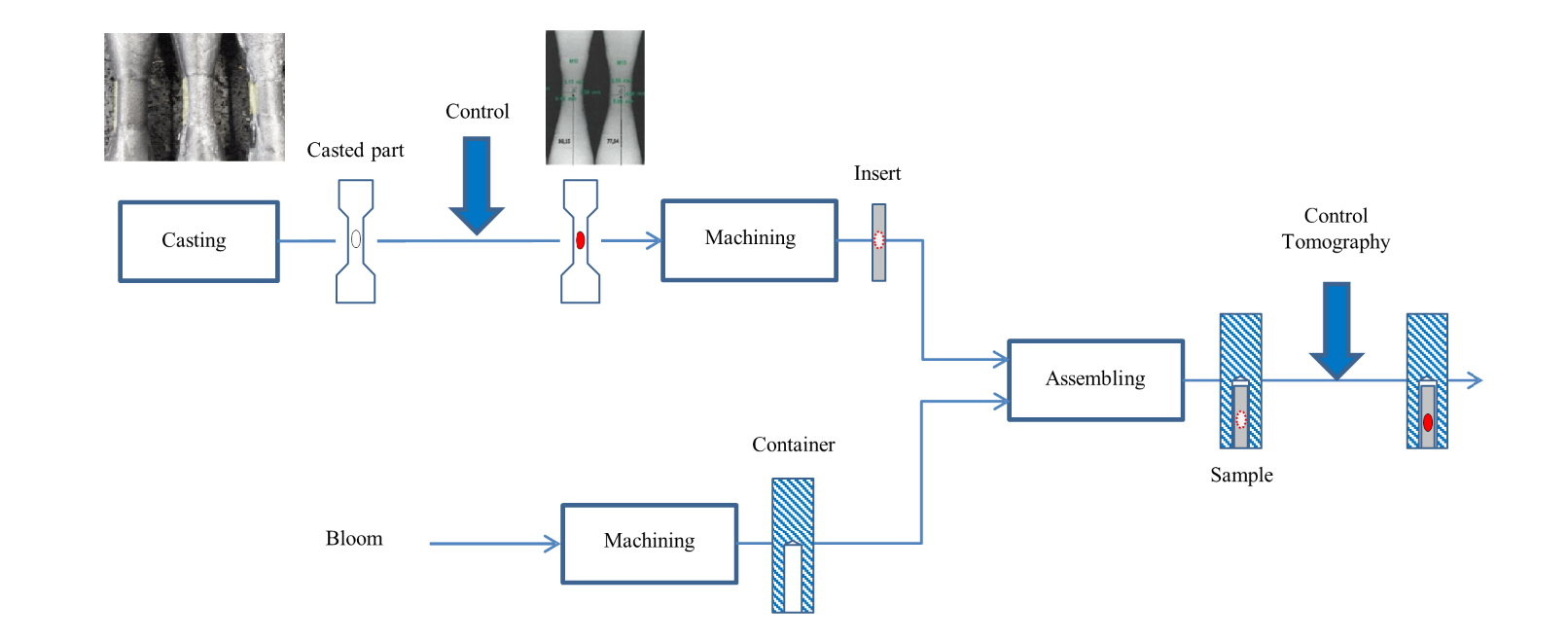
Fig. 1. Manufacturing route of the sample containing a controlled natural shrinkage porosity
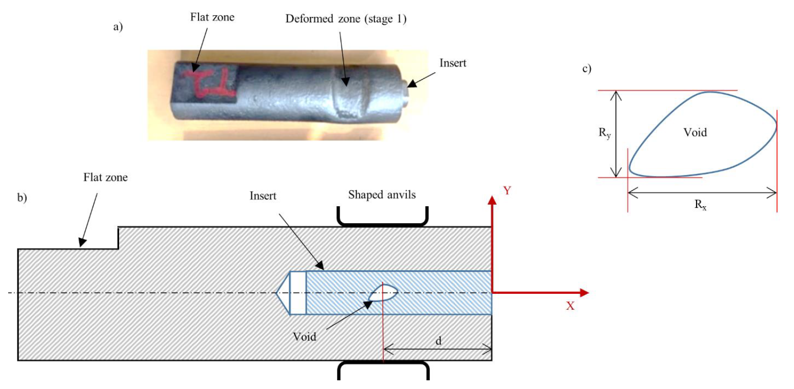
Fig. 2. Scheme of the sample, a) Photograph of the sample after the first forming stage, b) Scheme of the sample with its reference and its main-geometrical characteristics, c) Scheme of the void with its projected dimensions according to the sample reference
Table 1. chemical composition of the tested steel

2.2 The forming test
A representative forming test of the hot rolling of bars was previously developed by Pondaven et al. [15]. The tools consist of a succession of stands, each of them consisting of a couple of open-die anvils (See Fig.3.). The shape of the anvils corresponds to that of the industrial rolling stands on a 1/10 scale factor. The forming tests are carried out on a screw press SPR400. During the testing, the sample is held by a robot to control the position and the orientation of the void during the successive deformations. Between two forming stages, the sample is rotated 90° to reproduce the alternation of the forming direction. Before the forming, the robot maintains the sample few millimetres above the surface of the lower anvil to reduce heat losses.
The gap between the upper and the lower anvils are set independently from one stand to the other to control the deformation produced by each stage of the forming process. The sample is heated in an electric furnace and is manually transferred to the gripper of the robot. The anvils are not preheated, and no lubrication is applied.

Fig. 3. Robotised open die forging testing with shaped anvils [13]. a. Representation of the anvil profile and their relative position at the end of the stroke, b. Detailed representation of the anvils, c. Photograph of the seven shaped anvils, and d. Photograph of the sample hold by the robot during testing
In this paper, only the first two stages are experimentally studied. The samples after the test is air cooled down to room temperature. The tomography of the sample before and after the forming test is used to obtain the global shape of the void and allows the calculation of its volume and its projected dimensions according to the axis of the sample reference. The tomography is carried out with a resolution of 35μm achieving a good compromise between the necessary accuracy of the measurement and the tomography capability.
3 Modelling and Simulation
The Finite Element simulation are carried out on FORGE® software. It utilises an explicit representation of the void. Because of the size of the void with respect to the one of the sample and to limit the number of elements, mesh refinement boxes are used. The mesh size of the sample is progressively refined from the not deformed zone of the sample to the vicinity of the void by using 4 mesh boxes. The mesh boxes are centred, and the mesh size between two successive boxes is halved. The mesh size of the different boxes was studied by a convergence study in a previous work of Pondaven et al. [16]. A fourth meshing box is added compared to this previous work to be suited to the explicit modelling of porosities with a complex morphology without exceeding meshing capacities of the calculation. The mesh size of the more refined box must be low enough to represent the tortuosity of the void and to follow the reduction of the void volume during the forming process. Whatever is the mesh size of this box, the FE modelling will not be able to simulate the complete closure of the void. However, the more refined is this meshing, the farther the void closure can be simulated. The shape of the mesh boxes is ellipsoidal to be adapted to the elongation of the void according to the axis of the sample during the forming. The position and the mesh size of the different mesh boxes are illustrated in Fig.4. Because the irregular shape of the void, the model has no symmetry that would allow the reduction of the number of elements.
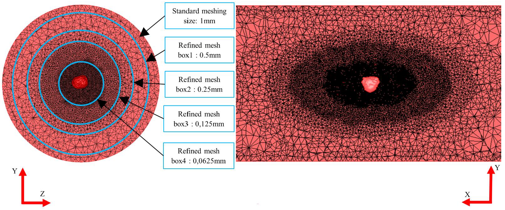
Fig. 4. Sectional views of the meshing of the sample with the different mesh boxes
The flow stress of the material, 𝜎0, is modelled by a Hansel-Spittel law (see equation 1 where 𝜀, 𝜀̇ and T are the equivalent plastic strain, the equivalent plastic strain rate and the temperature respectively). The material coefficients A1, m1, m2, m3 and m4 are given in Table 2.

A Tresca limited Coulomb law is assumed for modelling the friction between the material and the anvils (see Table 3). The temperature within the sample is calculated considering the thermal exchange with the anvils and the environment and the energy dissipated by friction and plastic deformation. The thermal exchange coefficient and the emissivity of the material utilised in the simulations are given in Table 3. The simulation consists of two steps, the transfer from the furnace to the press followed by the forming stages. In this paper only the first two stages are simulated.
During the deformation, the internal surfaces of the void will get into contact with each other. Unilateral sticking conditions are applied to these contacts that means that no slipping is allowed but they can unstick if the normal stress at the contact becomes positive. It is supposed that the contact time is not long enough to generate bonding and a change in the forming direction, for instance, may reopen them.
Table 2. Hansel Spittel coefficients

Table 3. Friction coefficients and Thermal exchange parameters

The implementation of the void geometry in the simulation, illustrated in Fig.5., consists of 3 steps. Firstly, the tomography produced a set of voxels with for each of them a grey level. A threshold parameter is applied to determine the subset of voxels corresponding to the void. The volume of a voxel is defined by the resolution of the tomography (35μm). The obtained volume after tomography exhibits lot of small-sized irregularities all around the void. These are due to the smallest details of the tortuosity of the shrinkage cavity, or to measurement noise or artefact. Whatever the origin of this, these details cannot be considered by the simulation. The geometry is thus treated to obtain a smooth geometry suitable for the FE simulation. Finally, the smoothed is implemented in the finite element simulation by a Boolean operation. The meshing of the sample in the vicinity of the void leads to a new discretisation of the internal surface in relation to the mesh size of the refinement box.
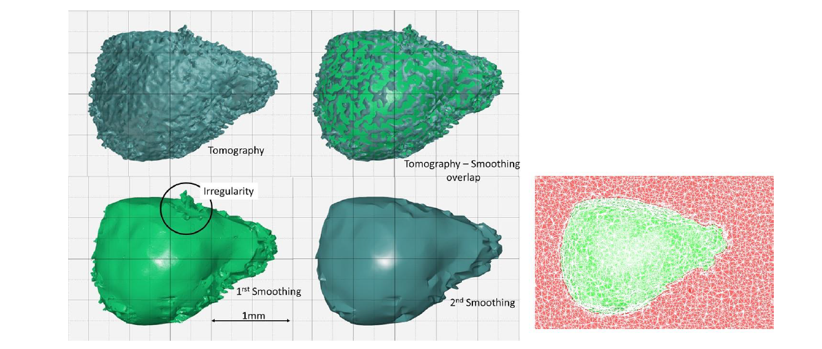
Fig. 5. Integration of the void geometry within the numerical simulation
4 Results and discussion
The first result concerns the shape at the end of the first stage of the forming test. The geometry of the void obtained by tomography and by simulation at its initial state and after the first stage are shown in Fig.6 (sample T8) and Fig.7 (Sample T9). In this figure, one can notice that the global shape of the void at the end of the forming stage is quite well reproduced by the simulation. However, the tomography result of the void after forming exhibits a protuberance (see detail in Fig.6.) that is not noticeable on the tomography performed before forming. This protuberance can be due to nearly closed zones of the initial cavity, too thin to be observed by tomography, which reopens during forming.
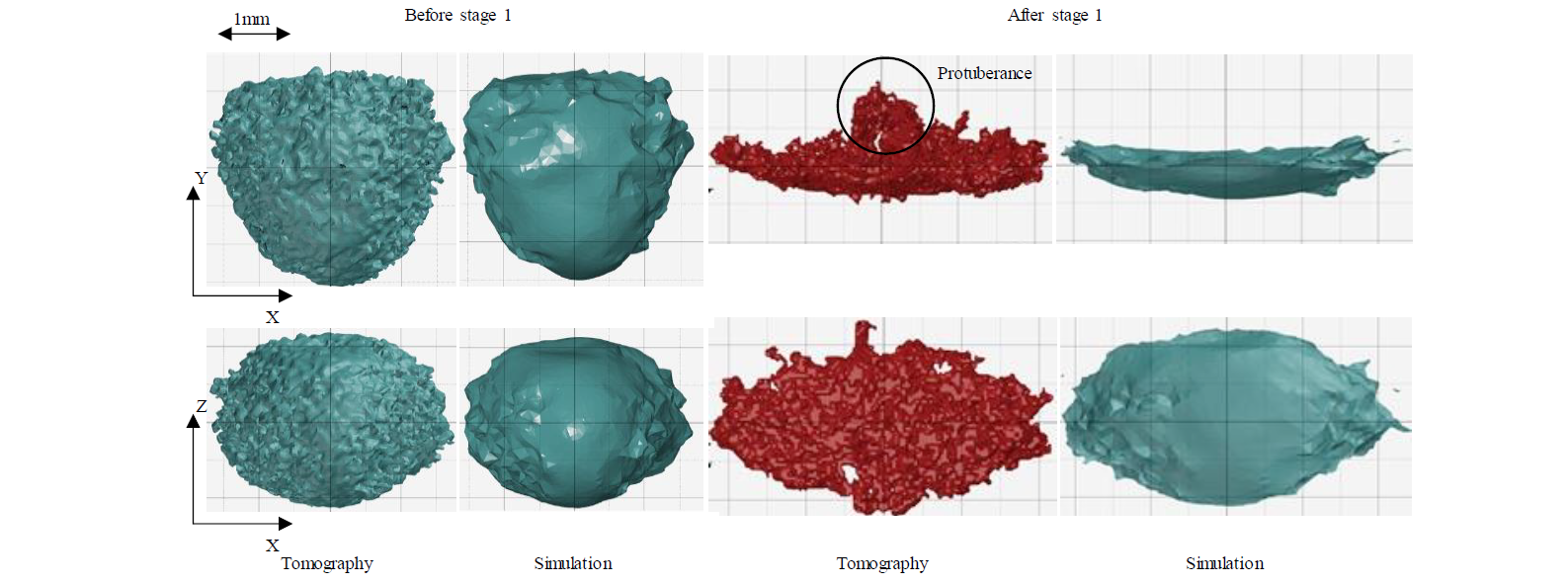
Fig. 6. Geometry of a void T8 measured by tomography and simulated, before and after the stage 1
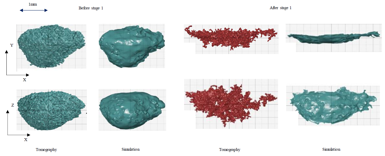
Fig. 7. Geometry of a void T9 measured by tomography and simulated, before and after the stage 1
Quantitative comparison between simulations and measurements were achieved by considering the evolution of the volume ratio (V/V0) of the void and the ratio (Rx/Rx0, Ry/Ry0, Rz/Rz0) of its dimensions according to the different axis of the sample reference (see Fig.2.). In these ratios, the index 0 designates the initial value of the considered parameter. The obtained results presented in Fig.8. are plotted according to the equivalent strain calculated in the centre of the sample by a simulation without void. Results are presented for two initial voids T8 and T9 which initial tomography is shown in Fig.6 and Fig.7 respectively.
The obtained results show that the void volume decreases with the deformation. The simulated volume ratio at the end of the first stage is quite in accordance with the measured one by tomography. Concerning the dimensions, the void is elongated in the axial direction of the sample and is flattened according to the forming direction while no obvious transverse widening is observed. At the end of the forming stage, the simulated dimension ratios are in a good accordance with the measured one. The maximum error, obtained for the forming direction (Y), is probably due to the low value of the dimension according to this direction, thus emphasising the measurement error, or to the emergence of the protuberance.
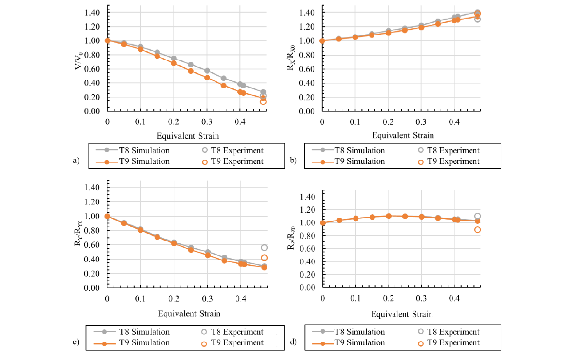
Fig. 8. Evolution of the void geometrical parameters during the first stage, a) volume ratio, b), c) and d) the projected dimension ratios
The results obtained for the first stage allow considering the simulation performance as satisfactory. The simulation is then utilised to predict the evolution of the void during the second stage of the forming test. In Fig.9. is plotted the evolution of the void volume ratio during the first and the second forming stages. One can notice an increase in the volume ratio at the beginning of the second stage. This phenomenon is due to the flat morphology of the void at the end of the first stage, flatness according to a plane that contains the forming direction (Z) of the second stage (see Fig.9.). This effect is thus an effect of the alternation of the forming direction.
In Fig.9. is also shown the internal contact surfaces predicted by the simulation. These surfaces form at the periphery of the void and are oriented quite perpendicular to the forming direction. According to the simulation, the alternation of the forming direction seems not to reopen this contact although the contact behaviour model allows this.
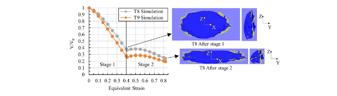
Fig. 9. Simulation of the evolution of the void during the first two stages where the internal surface contacts are shown in yellow
5 Conclusions
The present study was dedicated to the experimental and numerical implementation of a forming testing which is representative of the hot rolling of cast blooms with respect to the shrinkage cavity closure phenomenon. The testing consists in applying a multistage open die forging route with alternations of forming direction to a sample containing a solidification shrinkage porosity. The initial geometry of the void was obtained by tomography as well as the geometry at the different stages of the testing. The results obtained by a full-field model of the test are quite in good accordance with the experimental measurements. The FEM can predict the evolution of the volume of the void, and of its dimensions projected according to the direction of the sample reference. The simulation can predict the increase of the void volume at the beginning of the second stage of the test after the change in the forming direction. The new forming direction applied on the void flatten by the previous stage produces an increase of the void volume at the beginning of the second stage.
The validation of the numerical model by experiments chaining the first two stages remains to be performed. If the validation of the full-field model is confirmed, it can be used for a more extended design of experiments to characterise void closure during hot rolling of bars.
Acknowledgements
The authors would like to thank the Centre Technique des Industries de la Fonderie, CTIF, for their technical support and the supply of the cast samples. The authors are grateful to Alexandre Fendler for his technical contribution during the experiments. Lastly, the authors express their thanks to ISEETECH for the provision of the VULCAIN Platform facilities.
