1 Introduction
Powder Bed Metal Additive Manufacturing (PBMAM) technology is widely accepted and recognized as advanced manufacturing. The design and production of high-performance components is within reach for industry. Nonetheless, it is essential to have a better understanding of the powder-based feedstock materials, processes, structures, and properties to produce reliable PBMAM parts. In PBMAM processes, physical phenomena occurring during the layer-by-layer manufacturing, microstructure evolutions and mechanical properties of printed part are closely linked. Three different scales can be identified, (i) microscale, (ii) meso scale and (iii) macroscale. In this context, it is essential to predict melt pool dynamics involved during PBMAM process since microstructure evolution and microscopic defects depend mainly on the melting of powder layer and the solidification of the melt pool.
For process modelling, physics-based approaches are developed at meso scale. Meso-scale melt pool models can predict fluid flow and temperature distribution based on a multi-phase approach. The melt-pool model is computationally intensive in comparison with heat conduction model, the former is usually restricted to a layer deposition. Several discretization schemes to treat the multiphase flow can be found in the literature. In this work, a high order Discontinuous Galerkin scheme is used to provide high order convergence on unstructured mesh. This enables to capture with high accuracy those physical phenomena for such moving interface problem. The proposed CFD melt pool model is based on enthalpy-porosity formulation. This model is dedicated to hydrodynamics simulations under thermocapillary effects and thermal effects during solid liquid metal transition.
The numerical challenges of simulating multiphase flows are strongly related to the discontinuity in properties at the interface and jump conditions to be satisfied [3]. Multiphase problems imply a discontinuity in the solution (strong discontinuity) or in its derivative (weak discontinuity) on an interface evolving with time. To capture the discontinuity, two techniques are studied in this work the diffuse and the sharp interface methods. Diffuse methods smooth the discontinuities over a transition region across the interface. Sharp methods modify the stencil of the numerical scheme locally and can thereby keep the order of convergence of the method even in the vicinity of the interface.
The multiphase numerical treatment dedicated for each interface (solid-liquid and metal-gas interface) is described in the first section. And a numerical simulation of a static laser shot applied on Ti-6Al-4V resulted from the proposed model is illustrated in the last section.
2 Powder-bed fusion model
2.1 Solid/liquid interface
For most metallic alloys, the transition from solid to liquid state is applied over a range of temperature. A diffusive method is considered to smoothly represent the solid/liquid interface. In most diffuse numerical methods to treat liquid/solid interface, the mathematical model is modified to implicitly integrate the jump conditions in the constitutive law [4]. This approach uses a macroscale model where the microstructure in the mushy zone is not captured accurately. The solid and liquid phases are modeled as one single phase and the energy and momentum conservation laws are modified to distinguish locally the presence of liquid or solid phase. In order to integrate the jump condition for the energy equations, the classical enthalpy method is used [5]. This technique can describe the latent heat evolution by integrating the latent heat absorption during phase change in the mathematical model. For the momentum equation, a porous model is applied which consists of adding a source term to the momentum equation to penalize the velocity in the solid region.
The numerical model implemented in Argo uses a classical enthalpy-porosity constitutive law accounting for hydrodynamic and thermal effects occurring during the phase transition from solid to liquid metal. The system of equations considered is the incompressible Navier-Stokes equations augmented with phase-transformation thermodynamical effects, porosity-based mushy-zone modeling, Marangoni free-surface stresses and buoyancy-induced natural convection terms [1]. The system can be written as follows:
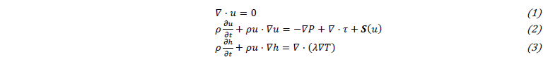
with u, the velocity vector, ρ the density, P the pressure, τ the viscous tensor, S(u) the source term described below, T the temperature and λ the thermal conductivity. The enthalpy h includes the latent heat for phase transformation weighted by the liquid fraction α:

where cp is the specific heat capacity, Lm the latent heat and α the liquid fraction which can be expressed as:

In practice, the dependence of the liquid fraction on the melting temperature is smoothed to ensure differentiability of the model [1] using a hyperbolic tangent:

The liquidus temperature Tl specifies the temperature above which a material is completely liquid while solidus temperature Ts specifies the value at which the material is considered solid. Fig. 1 illustrates the change of phase and the evolution of the volume fraction and enthalpy for a solid with rising temperature.
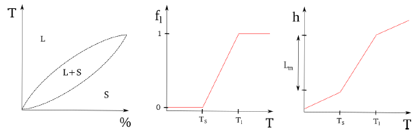
Figure 1: Phase diagram and evolution of the volume fraction and enthalpy with the temperature
The source term S(u) in Eq. 2 includes two contributions for the natural convection and the porosity penalty term to model the solid phase. The Boussinesq approximation is used to model the natural convection is expressed as follows:

where, β is the dilation coefficient and g represents the gravity vector. The Carman-Kozeny [6] penalty term, which ensures negligible velocity in the solid phase, can be written as:
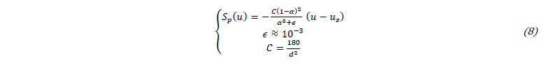
where the constant ϵ prevents a division by zero and the constant C is computed based on the interdentritic distance d shown in Fig. 2.
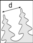
Figure 2: Interdentritic distance to evaluate permeability of the mushy zone
2.2 Liquid/gas interface
While for most materials studied a numerical diffuse method can be used for the first interface type since the transition from solid to liquid is smooth, the gas-liquid is a sharp transition with large jump in properties. Therefore, sharp interface techniques are in theory more appropriate but are also more complex to be implemented.
Currently, a diffuse approach based on Continuum Surface Force method has been implemented within Argo to treat multiphase flow for additive manufacturing processes [1]. A level-set variable ϕ is used to capture the gas-liquid interface Γ:

The variable ϕ represents the signed distance to the interface; hence the zero iso-value is the position of the interface and the sign defines the phase. The scalar ϕ is updated with the local velocity field by solving this advective equation:

Within Argo, the system of equations (9) is highly coupled with the resolution of the levelset [7]. The level-set method is illustrated in Fig. 3.a.
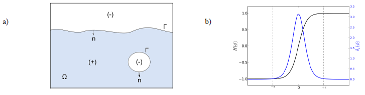
Figure 3: (a) Level-set method to capture the free surface (liquid/gas interface), (b) Regularization of material properties and interface conditions
The level-set variable is then used to regularize the properties across the interface using a hyperbolic tangent plotted in Fig. 3.b and expressed as:

For instance, the density across the interface can be computed as follows:

Interface conditions are enforced using a smoothed Dirac based on the level-set variable, those conditions are applied in a narrow band defined by a thickness ϵ around the zero iso-value as shown in Fig. 3.b:

For instance, to account for capillary forces at the interface, a source term is added in the momentum equation presented in system (2):

This term includes normal and tangential contributions of the surface tension noted σ. The normal force requires the evaluation of the surface curvature κ, and the tangential capillary force, which is referred to as Marangoni effect, includes the temperature influence on the surface tension:

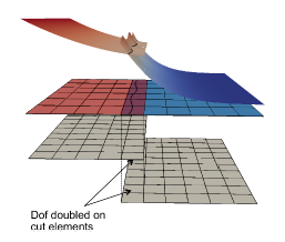
Figure 4: Illustration of the Extended Discontinuous method to capture discontinuities within cells
The major drawbacks of this diffuse method are i) the stiffness introduced when jump in the properties are large and ii) the high mesh dependencies to be able to represent this smooth transition. The smearing also introduces a degradation of the order of convergence in the vicinity of the interface, where phenomena driving the hydrodynamics occur. The idea of a sharp transition seems very promising to conserve the high-order convergence properties of Argo’s numerical method and to capture this kind of phenomena. A recent implementation to treat moving boundary problems sharply within Argo showed promising results [2] to simulate the liquid-gas interface. For this method, similarly to XFEM, the element cut by the interface are enriched to be able to represent a discontinuity (see Figure 4) within the cells. The nodes on these elements are duplicated, but the support of the solution is restricted by the sign of the level-set. This makes it possible to discretize a discontinuity (strong or weak) in the solution. The eXtended Discontinuous Galerkin method is described in several papers [7, 9] and Figure 5 illustrates the difference with respect to a diffuse method. The method has been implemented in Argo and verified on academic test cases for thermal problem mostly [2, 10]. The method has been proved to keep the high order convergence even in the vicinity of the interface if the quadrature on cut elements is chosen wisely. The spatial integration over cut cells is handled using the hierarchical moment fitting technique proposed in Muller et al. [9] and small cut cells are agglomerated to ensure the stability of the scheme [11].
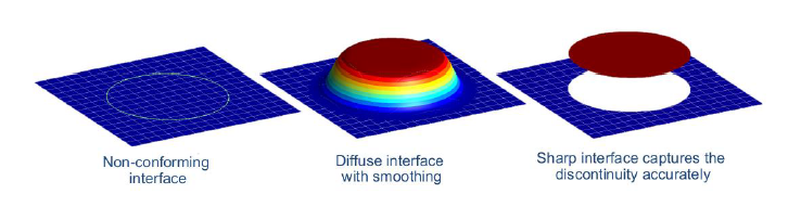 Figure 5: Comparison of diffusive and sharp interface methods for non-conforming interface mesh
The numerical study for additive manufacturing problems has shown the limits of diffuse methods when large jumps are considered and the challenges to impose accurately the interface conditions presented in [3]. The extension of the immersed interface method introduced in Argo seems promising and it is proposed to evaluate the challenges of extending the current method for hydrodynamic cases.
3 Numerical simulation
Current work is dedicated to improve and enrich the numerical model with additional physical phenomena such as vaporization. The diffuse and sharp interface capturing methods described before are both studied to highlight pros and cons of each approaches for PBMAM simulation.

where βr is the retrodiffusion coefficient which represents the proportion of vapor returning to the melt pool, M is the molar mass of the alloy, R is the universal gas constant, p0 is the atmospheric pressure and Lv is the latent heat of vaporization. The ejection of metallic vapor implies a force towards the melt pool. For the proposed model, this force fv is proportional to the saturated vapor pressure generated at the liquid/gas interface:

For the diffusive interface method, Eq. 16 and 17 are applied on the interface by using the smoothed Dirac function described in Eq. 13.
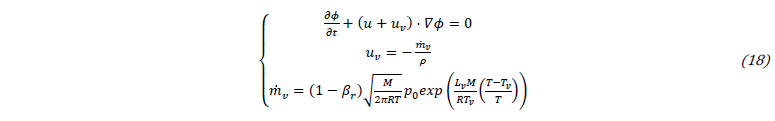
For the sharp interface method, the heat sink is directly applied on the interface as surface heat sink. The Eq. 10 is modified by including a velocity of vaporization proportional uv to the vaporization rate ṁv:
3.2 Static laser shot applied to Ti-6Al-4V
The 2D numerical test case consists in a titanium substrate exposed to a static gaussian laser flux qL expressed as follows:

where R is the reflection coefficient, PL is the laser power and r0 is the laser radius at focal point. In the case investigated, the power is equal to 250W with the radius of 50μm. Natural convection and capillary effect are also considered. The surface tension is not considered for this configuration and to limit the deformation of melt pool the Marangoni coefficient is reduced by two orders of magnitude. The material properties of the substrate and the gas are described in [12].
A symmetry plan is placed at the center of the laser heat flux and aligned with the laser beam direction. The domain sizes mentioned in [12] are duplicated. Adiabatic thermal condition and stick wall condition are imposed on lateral faces and bottom zone.
3.3 Results and discussions
Numerical simulations of the static laser shot presented in this section have been produced with the sharp interface approach including the vaporization model described in Eq. 16 and 18 during a simulation time of 150μs. The interface evolution is tracked at each time step and is represented by the zero iso-value level-set. The melt pool characteristics and evolution are illustrated in the Figure 6. The melt pool is bounded by the top surface and the white curve which represents the liquidus iso-value. Recirculation are constantly observed at the top edge of the melt pool layer and the flow is progressively intensified during the simulation as shown in Fig. 7. The temperature inside the melt pool is restricted and the maximum is closed to the boiling point due to the vaporization heat sink. The vaporization front progression and the melt pool thickness at the center of the heat source are measured for each simulation time. The simulation results show that the vaporization front progression is constant (increment of +18.5μm at each time step of 50μs) and the thickness of melt pool is constant during the vaporization (13.3μm). When the vaporization occurs on the surface of the melt pool, the vaporization velocity remains uniform due to a constant surface temperature near the boiling point (energy balance at the top surface) and the atmospheric pressure is fixed in this configuration.
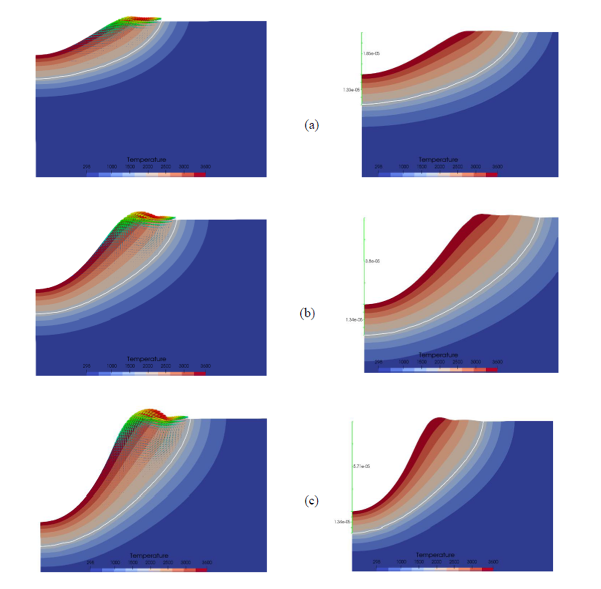
Figure 6: Evolution of the melt pool including temperature and velocity distribution near the heat source, vaporization length and melt pool thickness at the center of the heat source for different times: (a) 50μs, (b) 100μs and (c) 150μs
4 Conclusion & perspectives
To simulate and predict melt pool evolution during PBMAM processing, a melt pool model based on enthalpy-porosity formulation is currently in development. The main challenge remains the numerical treatment of the liquid/gas interface, the immersed interface method is proposed to succeed to the diffuse interface method.
Currently, main physical phenomena involved in PBMAM process are investigated such as vaporization. First numerical simulations have been performed with a vaporization model and have shown the important role of the vaporization in the keyhole formation.
Future work will be dedicated to surface tension application and thermal characterization of metal powder material.
