1 Introduction
For a large number of applications, additive manufacturing (AM) is becoming very attractive due to its capacity to manufacture products with complex and optimised designs which are not possible to achieve with conventional manufacturing processes. Regarding metal additive manufacturing, two types of techniques are commonly used, Powder Bed Fusion (PBF) in which the part is built in a chamber filled with successive layers of powder that are melted, and Direct Energy Deposition (DED) on which the material is locally added onto a substrate or a pre-existing part. While PBF allows for a larger freedom design and spatial resolution, DED techniques are more appropriated for larger components and higher printing rates [1].
Large aerospace components such as launch interface rings are parts on which additive manufacturing can bring cost savings by reducing the fly-to-buy ratio and the lead time for manufacturing for small series. Additionally, these load-bearing components are also good candidates to be topologically optimised in order to reduce its weight and save cost during the launching stage. Such rings have diameters of the order of a meter and would be impossible to be processed by PBF techniques due to the size limits of the printing chamber. Thus, DED techniques are better adapted in this case.
In this work, the feasibility of printing such a component in aluminium alloy using Laser Metal Deposition (LMD), a particular process of DED, is studied. In LMD the heat source is a laser and the feedstock is a metallic powder. Similar to welding, the heat source creates a molten pool which is fed, in this case with metallic powder, to create a cladded bead. A component or feature is thus created from the stacking of these beads in the Z-direction. A good set of deposition parameters and printing strategy can bring powder efficiency (the ratio of catch powder over blown powder) to over 90% [2].
Firstly, the processing parameters for printing two materials (AlSi10Mg and Scalmalloy®) are established, the heat treatment is tuned and mechanical properties are determined. Subsequently, the printing of a sector of the ring (30 out of 360°) is prepared accounting for the limitations of the equipment and the technology. Finally, a demonstrator is printed and tested in destructive and non-destructive ways.
2 Materials and Equipment
The materials used in this project are aluminium powders of AlSi10Mg and Scalmalloy from TLS Technik and Heraeus, respectively. It has to be noted that Scalmalloy has been developed mainly for powder bed processes and it has barely been studied for LMD [3]. The composition for both powders has been measured by induced coupled plasma (ICP). The powders have been characterized in a ZEISS scanning electron microscope (SEM) and the particle size distribution has been measured by optical means using a Retsch CamSizer and pressurized air.
The printing of the characterization coupons and demonstrators have been carried out in a custom laser metal deposition system with a 2kW laser diode and a coaxial nozzle on AA5083 plates used as substrates. The samples have been characterized using light microscopy, Vickers hardness, tensile testing on Zwick equipment, X-ray and dye penetrant.
3 Results and discussion
3.1 Powder characterization
ICP measurements provided in Table 1 revealed that the compositions are well within the specifications.
Table 1: Comparison of the compositions measured by ICP and the nominal values for AlSi10Mg and Scalmalloy powders
|
Element (Wt.%) |
Si |
Mg |
Fe |
Sc |
Zr |
Mn |
Al |
|
|
AlSi10Mg |
Nominal (EN AC 43000) [4] |
9.0-11.0 |
0.2-0.45 |
Max 0.55 |
- |
- |
- |
Bal. |
|
Measured |
9.0 |
0.4 |
0.16 |
- |
- |
- |
||
|
Scalmalloy® |
Nominal (3D Alchemy) [5] |
- |
4.0-4.9 |
- |
0.6-0.8 |
0.2-0.5 |
0.3-0.8 |
|
|
Measured |
- |
4.1 |
- |
0.7 |
0.3 |
0.46 |
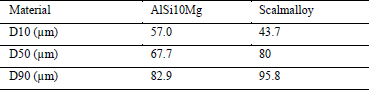
The descriptors of the powder size distribution are provided in Table 2. The powder distribution is a little bit broader for the Scalmalloy. This might hinder the flowing properties. However, as described for the morphology, this little impact in LMD. It must also be noted that for Scalmalloy, the lower fraction (D10) is quite important and out of the requirements for the equipment (45-115). Therefore an additional sieving was performed at CRM Group to remove the fraction of powder below 40 μm.
Table 2: Descriptors of the powder size distribution for both powders
The powders have been characterized using SEM microscopy. Two specimens per powder are observed. The first specimen is used to evaluate the morphology of the particles (sphericity, satellites…). The second specimen is hot mounted and polished to observe the cross section. The results of both observations are provided in Figure 1.
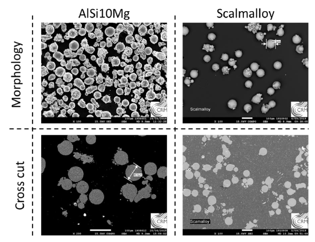 Figure 1: Morphology and cross cut of powders observed in SEM for (right) AlSi10Mg and (left) Scalmalloy
AlSi10Mg powder has some satellites than can decrease flowability. However, powder flowability in LMD has a lower impact in the quality of the process than it has in PBF processes. Thus, this amount of satellites is considered not to be detrimental to the process. The Scalmalloy powder shows a fairly good sphericity with also some few satellites on surface. Regarding the cross cut, a reduced amount of porosity is observed in the powder AlSi10Mg and almost none in Scalmalloy. Both powders show therefore a good quality under the SEM to be processed by LMD.
3.2 Parameter optimization
A full parameter optimization to obtain prints with a level of porosity lower than 0.5 % in volume was performed. The parameter optimization was carried out for three machine parameters: scanning speed [mm/min], power [W] and powder flow rate [g/min]. The porosity is assessed using optical observations and segmentation. The optimised parameters are not disclosed here. A picture of optimised microstructures showing low levels of porosity for AlSi10Mg and Scalmalloy are provided in Figure 2. Some of the pores are marked with red circles.
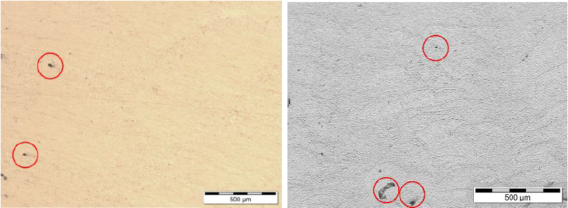
Figure 2: Light microscope observations of cross cuts for the optimized parameters for (Left) AlSi10Mg and (Right) Scalmalloy
The range of parameters selected for optimisation shows that it is possible to consistently obtain a porosity below 0.25 % for AlSi10Mg and below 0.5 % for Scalmalloy. The heat treatment for both materials consists on direct ageing of the specimens after printing. The ageing of AlSi10Mg is performed at lower temperature to activate the precipitation system common of Al-Si-Mg alloys [6]. The ageing of Scalmalloy consists on a higher temperature ageing to activate the precipitation of the Al-Sc-Zr system [7]. After tuning, the measured hardness for AlSi10Mg and Scalmalloy are 110 and 145 HV5, respectively.
Tensile coupons were then printed and heat treated to assess the mechanical properties of both candidates. The tests were carried out following the ASTM E8 standard [8]. For design and testing purposes, only the results in the Z-direction, the worst direction in terms of strength, are kept and provided in Table 3.
Table 3: Tensile results for the worst direction of AlSi10Mg and Scalmalloy
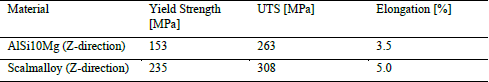
Scalmalloy show larger values of yield strength, ultimate strength and elongation. The lower values when compared to the same materials processed by PBF processes such as Selective Laser Melting (SLM) can be partially explained by the lower cooling rates achieved during LMD in comparison to SLM what results in a coarser microstructure and lower supersaturation of precipitating elements [3]. In view of these results, Scalmalloy is kept as the alloy to print the demonstrators.
3.3 Limits of the technique and model adaptation
In order to be able to print the demonstrators, preliminary tests have been performed in order to quantify the limitations of the LMD process. The first consists on assessing which is the maximum overhanging angle that can be printed with the chosen parameters, strategy and material. If the overhanging angle is too high, the contour bead of a layer can partially fall outside the previous layer, resulting in a defect that will propagate through the following layers.
For that purpose a volume with a continuously variable overhanging angle has been designed. This small volume with the shape of a twisted prism has an overhanging angle of 0° on one extremity and 30° on the other one. The printing of this shape allows to quantify at which overhanging angle the print becomes unstable. This part is shown in Figure 2-left. It has a length of 70 mm and the thickness of the section of 5mm, similar to the thickness of the walls in the demonstrator. Figure 3 reveals that the maximum overhanging angle is somewhere ~20° for this set of parameters and strategy. This is a fundamental information to further determine the printing strategy of the demonstrator. An additional check is performed to measure the actual section of the print and provide a correction to the software in order to better respect the tolerances.
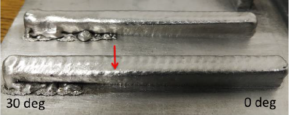
Figure 3: Printed volume used to assess the maximum overhanging angle printable with the current combination of parameters and material
Thus, with the provided information it is necessary to perform some modifications to the model. The structure produced by topological optimisation does not take in account the requirements for printing in LMD. The objective is thus to provide modifications to the part that add material only where needed to enable the printing. The extra material should be later removed by means of machining. Material is added in 3 types of regions:
-
Holes since support structures do not exists in LMD
-
Regions with a too large overhanging
-
Regions that have to be machined because of design requirements
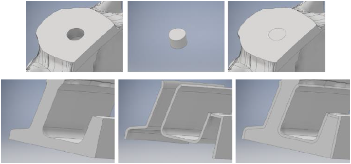
Figure 4: Modification of the CAD files for LMD-compatible printing. From left to right, original feature, added volume and the resulting combination. (Top) closing of a holes. (Bottom) addition of an over-thickness for machining
An example of the point i and iii are provided in Figure 4. Moreover, the L-shape of certain sections make it impossible to be printed with addition of few material. Thus, the printing is divided into 3 sequential steps that go as follows:
-
Printing of the main wall of the demonstrator
-
Turning 90° clockwise and print the internal part of the ring
-
Turning 90° anti-clockwise and print the external part of the ring
3.4 Printing of the demonstrator and characterization
Commercial software is used to generate the paths with the previously set parameters. A post-processing of the resulting G-code is carried out to make it compatible with the requirements of the LMD equipment. Three demonstrators were printed. The first one was used to detect and correct any errors of coding or dimensions and is not further shown here. A view of the second demonstrator is provided in Figure 5:
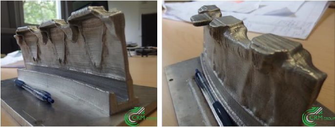
Figure 5: View of the printed demonstrator on Scalmalloy
While the overall behaviour of the print was OK, a printing defect (Figure 6 right) caused by the large overhanging was found at a position with one of the largest overhanging surfaces of the print (Figure 6 left). This resulted in a defect that propagated for several layers
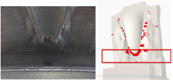
Figure 6: Defect found linked to the large overhanging surface shown in the image on the left. The red stain show the regions with overhanging angles over 15°
The demonstrators were subsequently machined and inspected using non-destructive means to find printing defects. 2D-Xray and dye penetrant were the chosen techniques. Dye penetrant testing did not provide any major indication (Figure 7). Some small pores were only revealed after the machining step. However, It was difficult to observe any defect in the not machined surface due to its roughness.
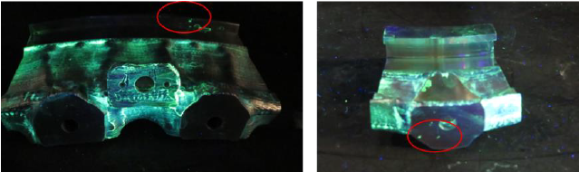
Figure 7: Dye penetrant testing on the machined demonstrator showing few small defects on the machined surfaces
2D-Xray are provided in Figure 8. None of the films revealed any defect. Moreover, it was not possible to trace back the defects observed after machining and revealed by dye penetrant in Figure 7. For this material and thickness it should be possible to easily detect pores of the order of 0.5 mm. Nevertheless, the surface roughness has also a similar order of magnitude, which makes difficult to evaluate X-ray analyses.
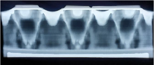
Figure 8: 2D X-ray control of the demonstrator. Thicker parts are shown wither than thinner ones
Optical microscopy was used to assess the amount and morphology of defects. Image analysis revealed that for this specimen the porosity is ~0.2% that is well into the specifications. Image analyses also revealed that the largest pores have dimensions of ~100 μm (with most of them being much smaller). This pore size cannot be detected using 2D-Xray and thus cannot observed in previous Figure 8. Thus, X-ray for this size of component and type of technique should be only useful to reveal large flaws such as lack of fusion where at least one of the dimensions is of the order of 0.5 mm.
Tensile tests performed on witness coupons built in parallel with the demonstrator confirmed that the strength of the material after heat treatment is in line with the one measured in the coupons from 3.2. Optical microscopy performed on these coupons also confirmed that the porosity is around 0.2%, which is well below the 0.5% required.
4 Conclusions and perspectives
Laser Metal Deposition was successfully used to print a spacecraft component. Two material candidates were successfully printed with porosity levels below 0.5%, AlSi10Mg and Scalmalloy. Scalmalloy showed larger values of strength than AlSi10Mg, making it the best option to print a demonstrator to prove the feasibility. It was also shown that, similar to PBF techniques, Z-directions shown the worst properties.
To print the demonstrator, it was shown that it was needed to measure the limitations of the technique, especially in terms of maximum overhanging angle. With this information it is possible to define and strategy for the printing of complex parts and provide modifications to the design were needed.
Despite of some defects the printing of the demonstrators was mostly successful in terms of material soundness and geometry. However, some defects linked to too high overhanging angles were still detected. The compatibility of non-destructive testing (X-ray and dye-penetrant) was also assessed. It was shown that both techniques are not well suited to detect small defects (below 0.5 mm) since the surface roughness add a level of noise comparable to the size of the defects.
Following this project, the next step is to print a full-size ring a robot system rather than in a gantry one. It will require a transposition of the processing parameters to a larger system and a re-evaluation of the design to account for the limitations of LMD but also for the possibilities of the additional degrees of freedom of a robot.
Acknowledgements
This work has been performed in the framework of ESA contract number 4000127605.
