1 Introduction
Additive manufacturing of metal parts is becoming more and more widespread because it allows greater part design optimization compared to conventional manufacturing techniques [2]. This optimization results in weight savings that are highly appreciated in many fields, particularly in the aerospace and automotive industries [3].
AlSi10Mg aluminum [4] is one of the most widely used metals in laser powder bed fusion thanks to its interesting strength-to-weight ratio. The very high cooling rate achieved in this additive technique enables obtaining a very fine microstructure, but defects are also present, such as porosities, inhomogeneity of the microstructure or residual stresses. The presence of these defects reduces the mechanical properties of the part [5]. In order to obtain better mechanical properties, good ductility and higher fatigue resistance, post-treatments have to be performed. While these are generally heat treatments, the post-treatment used in this article, friction stir processing (FSP), is of the thermomechanical type. The advantage of this post-treatment compared to the usual heat treatments is to decrease the percentage of porosities, which improves the fatigue properties [6].
Different methods exist to link the curves of normal force versus depth of penetration in load/discharge obtained by nanoindentation to the elastoplastic parameters. Dao et al. [7] studied 76 combinations of elastoplastic material properties and their indentation curves with sharp tips (conical, Berkovich and Vickers), developing functions linking the plastic properties of these materials and their curves. This method was completed by Bucaille et al. [1], [8] who established a more general formula based on a finite element analysis for different indentation angles and taking into account the friction between the punch and the material. This friction cannot be neglected for the sharpest indenters. The method covers a larger set of indenters, cones or other shapes, including the cube corner. It has been applied hereafter to determine the behavior of the Al matrix phase present in the material after FSP post treatment for future numerical simulations of Representative Volume Element. The final goal is to investigate the link between microstructure and fatigue strength. The behavior of each phase is a preliminary study. This method is already used in a numerical article devoted to indentation of materials with globular nodules within this conference [9].
2 Materials and methods
An EOS M290 machine was used to manufacture AlSi10Mg plates of 150x35x5 mm. The following optimized parameters were used: a build platform temperature of 35°C, a laser power of 390 W, a layer thickness of 30 μm, a hatch spacing of 0.19 mm, a scanning speed of 1300 mm/s and a rotation between layers of 67°. FSP was used as post-treatment to reduce the percentage of porosities and to break down and homogenize the secondary phase particles. A Hermle UWF 1001 H milling machine with a tool made of H13 steel was used for this process. During FSP, the tool penetrated the AlSi10Mg plate with a plunge depth of 4.7 mm and stirred the material with a rotational speed of 1000 rpm and a traverse speed of 500 mm/min. In order to preserve the fine Si-rich phase, only 1 FSP pass was performed [10].
The nanoindentation sample was cut perpendicular to the advance of the FSP tool. In this configuration, only the central part of the sample has undergone the thermomechanical treatment of the FSP. The specimen is embedded and mirror-polished. An OPS step is then carried out for 20 minutes to minimize the residual stresses due to polishing. The microstructure is analyzed using an electron microscope and the scanning mode of the nanoindenter.
The nanoindentations were carried out using a Hysitron Ti950 nanoindenter. Three pyramidal indenters were used for this analysis: a Berkovich indenter from Hysitron, a cube corner and an indenter with a centerline-to-face angle of 50° (called 50° hereafter) purchased from Surface. The indentation size was chosen to be large enough to be able to analyze the increase in load but small enough to be fully contained in the matrix. A penetration depth of 150 nm was chosen for the Berkovich indenter and the increase and decrease in load was controlled in depth. The increase in load is carried out in 5 seconds, followed by 5 seconds of holding then 5 seconds to decrease the load. The position of the different indentations is chosen after a scan of the surface in order to indent only the matrix. For the other two indenters, the depth of penetration was chosen to keep the contact area constant, to limit the indentation size effect [11]. Thus, for the 50° and cube corner, a penetration depth of 278 and 428 nm, respectively, was chosen.
The influence of the indented zone was studied. In addition to the aforementioned targeted indentations, two grids of 10x10 indentations, separated by 5 μm, are performed in the material, one with the Berkovich indenter, one other with the 50° one. The indented zones were therefore chosen randomly. The dispersion of the obtained results was compared with that of the targeted indentations.
The unloading (F, h) of the indentation is assumed to be fully elastic. For an indenter having a solid of revolution shape, Sneddon [12] has established the following link between the slope S at the beginning of this curve, the reduced modulus E* and the contact area A projected onto the initial surface of the material:

where the reduced modulus E* is defined by:

where E, ν and Ei, νi represent the Young's modulus and Poisson's ratio of the tested material and of the diamond used for the indenter, respectively, with Ei = 1.14.106 MPa, νi = 0.07 and ν = 0.3 and the projection of the contact surface A is defined by

where 𝐶0=3.√3.tan2𝛼, α being the centerline-to-face angle, C1, C2, C3, C4, etc. being coefficients taking into account small defects of the tip.
Using equation 1, the reduced modulus E* is calculated according to the unloading slope S as

And finally, using equation 2, the Young's modulus E of the indented material is obtained as

The geometry of the indenter can be replaced by that of an equivalent conical indenter having the same projected surface / penetration depth ratio. The relationship between α and the centerline-to-cone angle θ of the equivalent conical indenter is

Bucaille's method is based on the loading curve of the nanoindentations (F, h) which can be modeled by:

with F = normal force, h = penetration depth and C = constant.
On the other hand, Johnson [13] determined the following function linking the deformation representative of the indentation test εr,θ and the angle θ (see equation 6) of the equivalent cone:

Bucaille et al [1] established the following dimensionless function linking the representative stress σr θ of the test, the reduced modulus E* and the parameter Cθ (= C) of the indentation curve relative to a geometry of equivalent angle indenter θ.

The values of coefficients P1, P2, P3 and P4 are listed in Table 1.
Table 1. Parameters of the Bucaille method [1]
![Table 1. Parameters of the Bucaille method [1]](docannexe/image/2464/img-10.png)
The value of σr, θ in equation 9 is obtained using a solver.
3 Results and discussion
The as-built microstructure is shown in Figure 1a. The microstructure consists of α-Al cells surrounded by a Si-rich eutectic phase. After FSP, see Figure 1b, the microstructure consists of large globularized Si-rich particles surrounded by α-Al phase. Figure 1c presents an image of the FSP microstructure obtained using the scan mode of the nanoindenter. This type of image is used to determine the zones to indent, i.e., the areas where no silicon particles are visible.
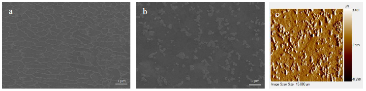
Figure 1: AlSi10Mg microstructure, a: as-built, b: after FSP, c: after FSP, using the scanning mode of the nanoindenteur
A representative sample of the curves obtained from the grids performed with the Berkovich and 50° indenters is shown in Figure 2, left and right. A significant dispersion of the curves is observed when using both indenters, at the beginning of the load increase (between 0 and 30 nm). When a Si precipitate is encountered, an increase in the slope of the curve is observed, before returning to the normal slope. Depending on the number of precipitates encountered, the load required to reach the 150 nm (278 nm for 50°) of penetration depth varied. The calculation of the Young's modulus for the different curves shows that the mean Young's modulus obtained by this method is close to that obtained using localized indentations (Table 2). The localized indentations are very time consuming compared to the grid and do not offer very different results. Indeed, the localization of the indentations only allows to avoid precipitates on the surface. However, since the indentations must be large enough to use the Bucaille method, the risk to encounter a Si precipitate below the surface is significant. Moreover, the size of the indentation used is close to the distance between the precipitates, which makes the precipitates on the surface very close to the indented area, influencing the results. For the cube corner, a grid has not been realized because this tip is fragile and an important dispersion of the curves is observed because of the higher penetration depth.
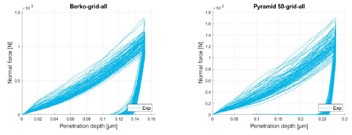
Figure 2: Representative sample of the curves obtained from the grids. Left: Berkovich, right: 50°
Table 2: Young modulus of α-Al matrix based on localized indentations and, for Berkovich and 50° indenters, curves from a 10x10 grid and Young modulus obtained from the ten lowest curves
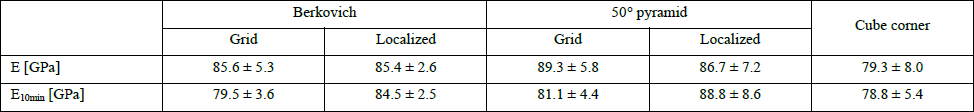
Since the following analysis is based on the α-Al matrix data, a selection of curves has to be made. To eliminate as much as possible the influence of Si precipitates, the lowest curves are chosen. By selecting the ten lowest curves (Table 2 – E10min), the Young's modulus decreases strongly for the two 10x10 grids while it remains stable for the targeted indentations. The grid allows to choose the areas less influenced by precipitates, whether they are on the surface or below. The Young's modulus obtained from the two grids and from the indentations made with the cube corner are compared with the value obtained from four tensile tests. These tests were carried out on samples of AlSi10Mg-FSP material [10]. As they showed good reproducibility of the results, the average curve of these macro-tests was used to estimate the Young macro modulus (E = 71.5 GPa) of the composite (Matrix + particles). Moreover, the slope of the micro elasticity, evaluated by the indentations (Eave = 79.8 GPa) and corresponding to the α-Al matrix, does not fundamentally differ from the macroscopic behavior of the material.
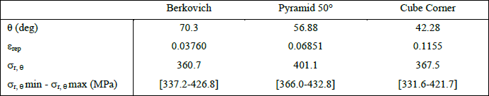
The curves selected to apply the Bucaille method are shown in Figure 3 for the three indenter geometries. These curves are similar to the one chosen to compute the Young modulus. Then, the Bucaille method is applied on each curve to determine the three representative points of the stress/strain curve and their ranges (Table 3). These results are compared with the tensile curve shown in Figure 4 representing the elastoplastic behavior of the macrostructure.
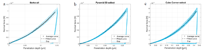
Figure 3: Nanoindentation curves used for Bucaille methodfor the Berkovich (a), 50° pyramid (b) and cube corner (c) indenter
Table 3: Results of Bucaille’s method for the different indenters, providing one stress-strain representative point (εrep - σr)
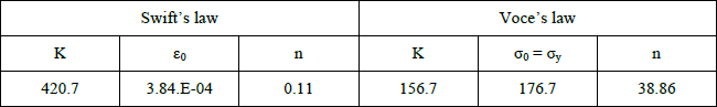
The following two static laws are used to describe the hardening from the results obtained by nanoindentation: Swift's law (equation 10) and Voce's law (equation 11).

Finite element tensile simulations on a material composed of an elasto-plastic α-Al matrix and elastic Si particles (of size representative of Fig 1b) showed that the composite (matrix + particles) elastic limit was only slightly influenced by the presence of particles in the material, however the hardening curve was affected. It is the reason why the elastic limit of the macro material was kept for the micro material. The behavior of the composite (hard particles in soft matrix) should present increased hardness compared to pure α-Al matrix behavior. Excluding the results of the Berkovich and 50° indenters performed only for very low indentation depth can be justified as it is well known that the beginning of these curves is not reliable. Note that this low indentation depth was chosen to indent only the matrix. So finally, we relied only on the minimum point determined by the cube corner to characterize the micro behavior (Table 4 and Figure 5). Voce's law gives better results than Swift's law, especially at the onset of plasticity.
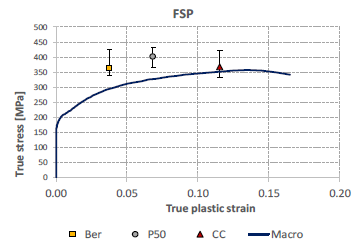
Figure 4: The three representative points of the α-Al matrix from nanoindentation curves compared with the macro curve obtained from tensile tests[10]
![Figure 4: The three representative points of the α-Al matrix from nanoindentation curves compared with the macro curve obtained from tensile tests[10]](docannexe/image/2464/img-18.png)
Figure 5: Voce’s and Swift’s lawsbased on the cube corner results
Table 4: Parameters of Voce’s law and Swift’s law obtained when considering the minimum point determined by the cube corner
4 Conclusions
To characterize the microstructure of a material, nanoindentations were performed and the Bucaille method was applied with three types of pyramidal indenters with different angles. These three tools and this method allows to obtain three points of the hardening curve of the matrix but only the last point was assumed reliable. Indeed, the description of the matrix hardening behavior was mainly based on the point relating to the sharper indenter which, as Bucaille specified, gives a better estimate of the behavior.
This study is a first step in micro characterization. The present results are currently used within exploratory simulations of the behavior of the material composed of two phases: matrix and inclusions [9].
The following two procedures were tested: automatic indentations following a grid and manually localized indentations in the material outside the silicon particles. The automatic procedure, much faster since the indenter works autonomously, saves considerable time. The curves of these tests were processed by a program to easily select the lowest curves corresponding to the behavior of the matrix. The results obtained are close to what is achieved by the manual procedure, and even better in the case of the Young modulus.
Acknowledgements
This research was conducted within LongLifeAM project of WALInnov program – Convention 1810016 Région Wallonne. As Research Director of F.S.R-FNRS, AM Habraken acknowledges the support of this Walloon Research Foundation. J. G. Santos Macías acknowledges the support of the Fonds de la recherche scientifique – FNRS (FRIA grant), Belgium.
