1 Introduction
Additive manufacturing is revolutionising the way metal parts are designed and manufactured. The Laser Metal Deposition - Powder (LMD-p) process enables applications such as cladding, part production and function addition. Each of these applications requires optimisation of machine parameters prior to manufacturing.
Originally, powder spraying technology was originally used only for cladding [1], [2], which explains why there is an abundance of literature on the subject [3]. Technological advances have made it possible to use a coaxial laser powder jet instead of a lateral one, which has led to the development of LMD-p technology itself, capable of manufacturing large volume parts [4]. The result is a more complex thermal history and phenomena due to the multiplication of layers. Depending on the machine manufacturer, the nozzles may have several diametrically opposed powder outlets (Trumpf®, LENS™) or a continuous 360° ring (BeAM®) forming a powder cone in each case. The design of the head greatly influences the speed of the powder flow [4], in addition to the speeds of the various gases used (lens protection, oxidation shield and powder transport).
It soon became necessary to simulate the process in order to predict the geometry of the manufactured track on the one hand, and the thermal history of the material [5], on the other hand, from which its microstructure (metallurgical phases, grain size and morphology, porosities) [6], [7] and mechanical properties are derived, and finally to optimise the machine parameters [8]. Numerous empirical "ground rules" have emerged before a more formal approach in the form of analytical and/or numerical models was obtained [4]. The majority of analytical models are based on a decoupling of the heat flow brought by the laser beam and the powder flow (e.g. [9]). However, they do not take into account the fact that the powder that impacts the melt pool tends to cool it, which leads to an overestimation of the size of the melt pool [10]. This is why numerical models based on CFD ([11]–[13]), FEM ([14]–[16]) or on a combination of the 2 methods ([17]) have appeared to reproduce with a greater fidelity the different physical phenomena involved. In [18], Pinkerton confronts analytical model and numerical simulation in order to predict the dilution and the width of a bead. Both models are then subjected to experimental validation; the numerical method tends to overestimate the size of the bead while the analytical approach underestimates it. Perhaps the most accurate solution then lies in a combined numerical and analytical method such as Peyre [19], [20]. This is also the line of research of the work presented here.
To this end, a semi-analytical model was developed, representing the attenuation of the laser beam by powder particles. This provides the preheating temperature of the powder as well as the attenuated laser power impacting the substrate. These data serve then as an input to a thermal Eulerian simulation which aims to estimate the width and the height of the track. The results of this simulation are then compared to experimental data carried out on a BeAM® machine.
2 Model description
2.1 General approach
The purpose of the model presented here is to predict the width of a bead deposited by the LMD-p process. It is compared to track dimensions obtained on a BeAM® machine, for different sets of parameters (laser power, deposition speed and powder flow rate) used. The general approach comprises three steps: the initial iteration consists of calculating the incident power, i.e. the effective laser power impacting the pool after powder attenuation, taking into account the losses induced by beam transport via a fibre. During this step, the temperature rise of the powder particles on their way to the melt pool is also estimated. The analytically calculated attenuated power is then used as an input to a steady-state thermal model, based on an Eulerian FEM formulation (Morfeo®). This second calculation step allows a first estimate of the size of the molten zone. This pool width cannot be considered equivalent to the width of the bead because the powder falling into the pool, which is colder, tends to shrink the melt area. This is why, using the semi-analytical model, the powder distribution determines how much material enters the pool and at which temperature, so a sink term quantifies the energy used to melt these particles. A few iterations then lead to a stabilisation of the pool width, resulting from a compromise between keeping the pool molten and adding cold material. This dimension is then estimated as the width of the track (cf. Fig. 1).
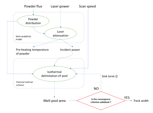
Fig. 1. Overview of the developed method combining a semi-analytical model and a thermal model
The BeAM has a 360° continuous powder output. Its laser beam is defocused with its focal point above the substrate as shown in Fig. 2. A primary gas (argon) protects the optical lenses and is discharged through the same orifice as the laser; a second carrier gas allows the powder to be conveyed by giving it an initial velocity. The special feature of the machine is that a third gas is supplied to the first gas, which is used to shape the powder jet.
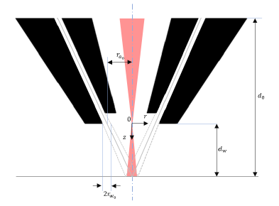
Fig. 2. Schema of BeAM® nozzle
The assumptions used for the model developed are as follows:
-
The flow is quasi-static in the semi-analytical model while the deposition speed is taken into account in an Eulerian thermal model. The particle velocity is assumed to be constant although this is not the case since the forming gas accelerates the particles. The effects of gravity and drag are neglected ([21], [22]).
-
Powder particles are assumed to be spherical and of constant radius, as in Diniz Neto [23]; this tends to be true for powder produced by gas-atomisation [24].
-
Interactions between particles such as collisions or shadow effects are neglected [25], power losses due to second reflections are also neglected [26].
-
The laser beam is considered to be cylindrical with a radius of 𝐿 for the sake of simplicity, despite it is defocused (cf. Fig. 2); and its intensity distribution is considered to be top-hat (cf. Figure 4 in [24]).
Table 1. Nomenclature and values taken in the model
|
Designation |
Symbols |
Values |
Units |
|
Powder nozzle radius |
𝑟𝑎0 |
1.45 |
mm |
|
Half powder nozzle outlet |
𝑟𝑤0 |
0.26 |
mm |
|
Working distance |
𝑑𝑤 |
3.5 |
mm |
|
Height of powder flow |
𝑑0 |
4.78 |
mm |
|
Powder mass flow rate |
F |
g.min-1 |
|
|
Powder distribution |
Dr |
kg.m-2.s-1 |
|
|
Laser power |
P0 |
W |
|
|
Laser beam radius |
L |
3.18 x 10⁻¹ |
mm |
|
Initial laser intensity |
I0 |
W.m-2 |
|
|
Initial particle speed |
𝑣 |
1.76 x 10² |
m.s-1 |
|
Component of v in the z direction |
𝑣𝑧 |
m.s-1 |
|
|
Powder particle radius |
rp |
37.5 |
µm |
|
Density of particle material (at 298 K) |
ρ |
4429 |
kg.m-3 |
|
Laser beam intensity |
Ir(z) |
W.m-2 |
|
|
Incident laser power |
Pi |
W |
|
|
Coordinates of particle from the nozzle outlet to (Z,R) position |
(r’,z’) |
||
|
Position of powder particle |
(Z,R) |
||
|
Axial component of the velocity of a particle in the right path |
𝑣𝑧’ |
m.s-1 |
|
|
Absorptivity of powder particle |
α |
0.4 |
|
|
Specific heat capacity (at 298 K) |
cp |
538 |
J.kg-1.K-1 |
|
Ambient temperature |
T0 |
298 |
K |
|
Temperature of particle at (Z,R) position in the melt pool |
TinPool |
K |
|
|
Thermal conductivity (at 298 K) |
k |
7.19 |
W.m-1K-1 |
|
Melting temperature |
Tfusion |
1898 |
K |
|
Specific latent heat of fusion |
Lfusion |
2.86 x 10⁵ |
J.kg-1 |
|
Sink term |
Q |
kg.m-2.s-1 |
2.2 Semi-analytical schema
Let's start by writing the radii 𝑟𝑎 and 𝑟𝑤 which define, respectively, the mean radius and the half-width of the powder jet ring at a distance 𝑧:

As most papers suggest (e.g. [12], [13], [22]–[25]), the distribution of particles (5) within the powder jet can be represented by a 𝑇𝐸𝑀01* Gaussian function (cf. Figure 3.11 in [3]). To do so, two components 𝐶1 (3) and 𝐶2 (4), are calculated, both of which have units similar to an area:

The powder mass flow rate per unit area is then given by the following relationship and represented in Fig. 3:

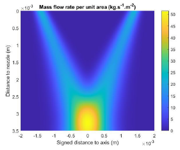
Fig. 3. Numerical representation of particles distribution within the powder flow
The laser intensity is considered to be uniform over the entire cross-section of the beam. Beer-Lambert's law expresses the intensity of the beam at a distance z from the nozzle exit [25]:

With 𝑣𝑧 being the velocity component in the 𝑧-direction of the powder particles.
By integrating the intensity 𝐼𝑟(𝑧=𝑑𝑤) over the entire cross-section of the laser beam we obtain the incident power 𝑃𝑖 which impacts the melt pool:

In order to predict the temperature to which the powder particles are heated before impacting the molten zone, it is necessary to express their trajectory using their coordinates (𝑍,𝑅). For the sake of simplicity, linear trajectories are considered here, although the different gases play a role in the deflection of the particles; however, as shown by Lin (Fig. 4 in [27]), the fact that the inner nozzle is slightly set inward from the outer nozzle tends to form a straight jet. The trajectory equations (8) can be reformulated as a function of 𝑟.

On the other hand, the z component of the particle velocities (10) can be written as follows:

The temperature of the particles [23] that fall into the pool, i.e. those whose coordinates are 𝑍=𝑑𝑤 and 0<𝑅<𝐿, is finally estimated using the relation:

where 𝑣𝑧′′ and 𝑧′′ are respectively the velocity and the altitude of the particles originating from the opposite powder stream.
The time during which the particles pass through the laser beam is not sufficient to reach their melting temperature; this is why a portion of the incident power is allocated to melt this colder added mass. This leads to introduce in the Eulerian thermal model, a sink term reflecting this phenomenon. This corrective term takes the form of a flux applied in the powder's impact zone, and of opposite sign to the heat flux brought by the laser. It is obtained by the following relationship:

Where 𝐿𝑓𝑢𝑠𝑖𝑜𝑛 is the specific latent heat of fusion.
2.3 Steady state Eulerian thermal model
The incident power, noted 𝑃𝑖 estimated using the semi-analytical model, allows the definition of an equivalent heat source in the Eulerian thermal model (Morfeo®). In this model, the heat source is fixed and a section of material, initially at room temperature, moves at the deposition speed (travel speed). A stationary solution is obtained at a lower calculation cost (cf. Fig. 4). In addition, a localised refinement of the mesh in the heating zone guarantees greater precision in the heat input.
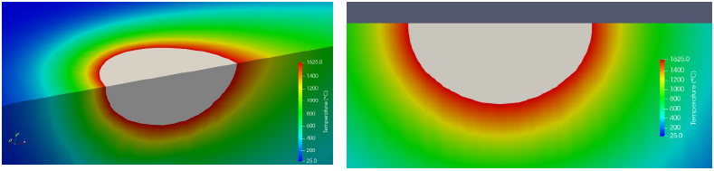
Fig. 4. Temperature field obtained from Eulerian model: melt pool is coloured in grey
This model takes into account the variation of the material properties 𝑘, 𝑐𝑝 and 𝜌 with temperature. In addition, it considers heat loss by convection and radiation. A first calculation allows a rough estimate of the dimensions of the melted zone. The quantity of powder "captured" by the melt pool can then be estimated and the corrective term is calculated according to equation (12). The successive iterations then consist in adjusting the corrective term until the size of the pool predicted by the model converges (cf. Fig. 5).
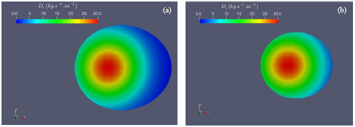
Fig. 5. Powder distribution spread over the surface of the pool (a) First iteration (initial), (b) Fifth iteration (final)
3 Experimental data and validation
The material adopted for this experiment is a Ti6Al4V powder (supplied by Tekna Inc.). The small nozzle configuration of the BeAM® machine is used, the dimensions and values necessary for the simulation are provided in Table 1.
Table 2. Set of machine parameters used
|
Run number |
Laser power (W) |
Incident power (W) |
Scan speed (𝑚 𝑠−1) |
Powder flow rate (𝑔 𝑚𝑖𝑛−1) |
|
1 |
660 |
570 |
1000 |
3.5 |
|
2 |
360 |
236 |
1500 |
1.5 |
|
3 |
660 |
570 |
2500 |
3.5 |
For each set of parameters shown in Table 2, a total of 5 iterations were necessary to obtain a stabilised melt pool. Figure 6 illustrates the fluctuation of the predicted track width during the calculation.
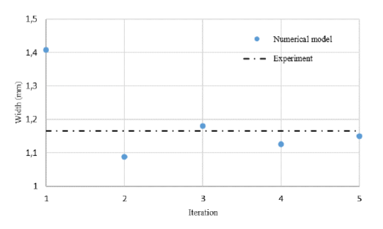
Fig. 6. Convergence of melt pool width (Run 1) after 5 iterations
After stabilisation of the track width, the cross-section area is estimated, considering the powder mass flow rate distribution and the travel speed. Both width and area are finally used to estimate the track height, by making the hypothesis that the cross-section exhibits a circular shape. Estimated width and height are presented in table 3.
Table 3. Experimental and simulated results
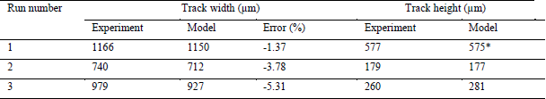 * this height corresponds to the maximum value achievable with a semi-circle approximation, but it is underestimated.
The bead width resulting from the model is, in a general way, underestimated. The relative error increases when the melt pool size decreases. This can be explained by the fact that the mesh size is fixed: any partially melted element is considered as part of the pool, whether it is only slightly or completely melted. This feature can be improved with a remeshing strategy performed during the iterations. Moreover, in order to apply this model to wider melt pools (high energy densities), it seems necessary to include the dynamics of fluids within the melt pool (especially Marangoni effect) [20]. As for the height estimation, the circularity hypothesis provides relatively good trends. However, some phenomena like surface tensions and/or gravity effect tend to flatten the bead and to induce more specific cross-section forms, that cannot be captured with such a model.
4 Discussion and conclusion
A combined model based on a semi-analytical approach and a steady-state thermal Eulerian formulation has been developed to predict the height and width of a track deposited with LMD-p technology. Experimental validation has been carried out on a BeAM® machine. Laser intensity attenuation as well powder preheating temperature are first estimated and used as input data for the calculation of the track dimensions. An iterative approach making use of a heat sink term has been successfully applied to calculate a stabilised melt-pool with a good approximation in a relatively short calculation time. However, a remeshing strategy capturing the actual contour of the melt pool at each iteration would be necessary to increase the accuracy of the track width approximation. Regarding the height, the prediction is less accurate due to gravity effects and surface tensions which are not considered in this work. Finally, in order to deal with larger energy densities, resulting in wide melt pools, the current model would require some adjustments, in order to account for the dynamics of the liquid material. One option as suggested by some authors, would be to consider an anisotropic thermal conductivity in the melt pool. Such an anisotropy could result from thermal gradient considerations, as it is the main cause for liquid material convection. This feature will be the object of future works.
Acknowledgements
This research project was undertaken with the assistance of resources and services from the ADDIMADOUR platform, Additive Manufacturing Solutions.
