1 Introduction
In recent years, thermoplastic composites have been working their way into larger aircraft structures. Thermoplastic matrices have major advantages over thermosets such as possibility of welding, recycling, and reduced cycle times. Automated processing techniques are now widely recognized as an advanced, reliable, and cost-effective way to manufacture thermoplastic composite structures. Automated tape laying (ATL), filament winding and automated fiber placement (AFP) are among the most used technologies. However, these processes are constrained by the use of molds and could be optimized to produce more functionally complex structures.
Additive manufacturing techniques such as fused filament fabrication (FFF) has the potential to manufacture complex geometry parts without the need of expensive tooling. FFF is a form of additive manufacturing where a semi-molten filament is extruded trough a heated nozzle layer by layer to form the desired shape. The extruded filament solidifies with the neighbouring filaments while cooling. Bonding among polymer filaments is driven by the thermal energy of the material. The bonding quality in the FFF process determines the integrity and final mechanical properties of the printed part. Production of more complex geometry composite structures with flexibility and customizability can be achieved through the combination of AFP with additive manufacturing [1] [2]. The challenge is to add functions or reinforcements (stiffeners, brackets, etc.) to composite parts manufactured by AFP, with additive manufacturing by FFF (Figure 1).
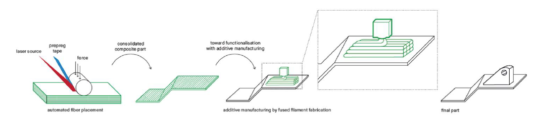
Fig. 1. Illustration of the combined automated fiber placement and FFF processes
The main issue concerns the bonding quality at the interfaces between printed layers, and between the composite part and the 3D printed function. Healing is achieved when two polymer surfaces are brought into close contact, through the interdiffusion of the macromolecular chains [3]. Diffusion is more likely to occur above the glass transition of the polymer and accelerates when temperature increases (Figure 2). The quality and strength of the bonding depends on different parameters: chemical affinity between the added material and the substrate, and thermal history of the materials. Thermal energy available at the interface and the cooling rate of the materials are key parameters that will determine the final bonding strength [4] [5].
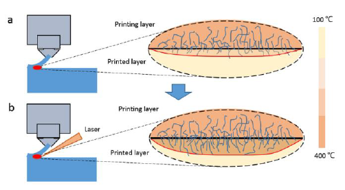
Fig. 2. Impact of an additional laser source on the interface temperature and illustration of the diffusion of PEEK macromolecular chains across the interface [5]
Composite laminates involved in this study are made of a poly ether ether ketone (PEEK) matrix reinforced with carbon fibers. Materials studied for the additive manufacturing process are PEEK and poly ether imide (PEI), both thermostable and high-performance polymers. These are very challenging to process with FFF because they require high processing temperatures. High thermal gradient cause partial and weak interlayer bonding that leads to apparition of defects in the printed parts and lower mechanical strength [6] [7] [8]. Rapid cooling prevents coalescence and healing of adjacent printed beads.
In this context, the first objective is to understand how process parameters impact thermal history of the materials and the bonding quality. The goal is to determine a process window where bonding strength is maximized. A preliminary test focuses on the influence of printing parameters on thermal history at the interface between a PEEK/carbon laminate and 3D printed PEI. The methodology for studying the impact of printing parameters on the cohesion and adhesion of printed parts with a composite laminate is described.
2 Preliminary test
2.1 Methodology
Previous studies have demonstrated that changing printing temperature, printing chamber temperature and printing speed has an impact on the final mechanical properties of PEI and PEEK printed parts [9] [10]. Some parameter sets give a better fusion between the beads which allows to reduce porosities inside printed parts and to obtain a better mechanical strength. This preliminary test was used to study the influence of extrusion temperature, printing chamber temperature and printing speed on the thermal history at the interface between printed PEI and a PEEK/carbon composite. PEI has been chosen for its mechanical characteristics and because it is totally miscible with PEEK in the amorphous state. PEI-9085 of 1.75 mm diameter provided by Kimya was used. The substrate was a single layer of PEEK/carbon tapes (60% volume fiber ratio), 0.2 mm thick, manufactured with AFP. 15 successive layers of PEI were printed at various speed and temperatures on the composite substrate, which was fixed to the 3D-printer plate. K-type thermocouple with a diameter of 0.05 mm was placed at the interface (Figure 3). This test was performed with a 3D-printer with a plate temperature of up to 200°C and a chamber temperature limited to 60°C. Variation between a minimum and a maximum value of one parameter at a time was considered. Each experiment was done 3 times.
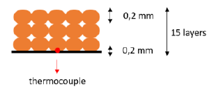
Fig. 3. Illustration of the localization of the thermocouple during the experiments
2.2 Results
The temperature profiles obtained for different processing conditions are shown on Figures 4 to 6. It shows that the temperature of the bottom layer rises above the glass transition of PEEK (143°C) with the deposition of each additional layer. Each peak is followed by a rapid decrease in the temperature as the printing nozzle moves away from the localisation of the thermocouple. The minimum temperature between each peak increased with the number of layers deposited. Temperature at the interface was higher all along the process when extrusion temperature was increased at 420°C compared to 360°C (Figure 4). The minimum temperature between the peaks was increasing more rapidly when printing speed was adjusted from 16 to 26 mm/s (Figure 5). Layers had less time to cool down. Increasing the printing chamber temperature from 40 to 55°C did not show any significant effect on the temperature profile at the interface (Figure 6). PEI is usually printed at chamber temperature from 150°C to 200°C but the increase of the chamber temperature was limited by the printer specifications in this study.
Even if the temperature at the interface remained above the glass transition of PEEK during most of the process, development of sufficient bonding between the first layer of printed PEI and the composite substrate did not occur. A 50 μm-sheet of pure PEEK was placed on the substrate to enrich the interface with polymer matrix, but the formation of bonds was still poor (Figure 7).
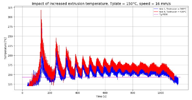
Fig. 4. Temperature profile at the interface between the first printed layer of PEI and the composite substrate.
Red curve: extrusion temperature of 420°C. Blue curve: extrusion temperature of 360°C. The purple line is the glass transition of PEEK
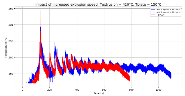
Fig. 5. Temperature profile at the interface between the first printed layer of PEI and the composite substrate.
Red curve: printing speed of 26 mm/s. Blue curve: printing speed of 16 mm/s
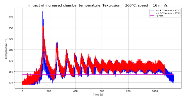
Fig. 6. Temperature profile at the interface between the first printed layer of PEI and the composite substrate.
Red curve: chamber temperature of 55°C. Blue curve: chamber temperature of 40°C
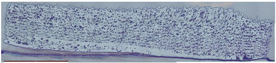
Fig. 7. Microscopic observation of the 15 layers of PEI printed on the thin sheet of pure PEEK.
There is no adhesion on one half of the sample
3 Experimental study
The experimental study is divided in 3 steps. First, the ability of the macromolecular chains of PEEK and PEI to diffuse is investigated. Self-diffusion of macromolecular chains in the bulk can be described with the reptation model established by De Gennes [11]. In this model, the reptation time is defined as the time needed by the chain to escape from its original configuration. The reptation times in PEEK and PEI are determined through rheological measurements. Then, the influence of printing speed, extrusion temperature and printing chamber temperature on the cohesion of PEEK and PEI printed parts is studied. Bonding quality and strength between extruded filaments of our materials are examined through microscopic observations and 3-point bending tests. Finally, the impact of process parameters on the adhesion between a PEEK/carbon laminate and printed high performance polymer is investigated. Bonding strength is examined through microscopic observations and double cantilever beam (DCB) test. The main goal is to determine a process window where cohesion inside the printed function and adhesion with the composite part are maximized.
3.1 Cohesion of the 3d-printed functions
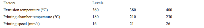
Influence of printing speed, printing temperature and printing chamber temperature on the bonding quality and strength of PEI and PEEK parts is investigated. The analyzed response is the porosity rate, which is determined with image analysis of microscopic sections of the samples. It is a good indicator of the partial bonding between printed beads. To evaluate the influence of the different factors on the response, Design of Experiments (DOE) was implemented as statistical method. Factors are analyzed in a full factorial design 33, which makes 27 total runs as shown in Table 1. The analysis of significance was performed by means of the analysis of variance (ANOVA) method with a significance value of 5%.
Table 1. DOE full factorial design with the different factors and levels considered
The most promising parameter sets are selected based on the porosity analysis. New samples are printed following those configurations, to be tested in 3-point bending tests. There are no standards for testing 3d-printed plastic parts. Therefore, tests conformed to ASTM standard D 1184-98 for flexural strength of laminated sheets bonded with glue as used by Sun et al. in their study but with some deviations [12]. Samples are made of 15 layers of 0.2 mm. Filaments are all deposited perpendicular to the longitudinal direction of the specimens so the test failure would occur in the bonds between adjacent filaments (Figure 8). 5 replicates are tested per configuration. DSC analysis are used to determine the crystallinity rate of the PEEK specimens.
The machine used to print the specimens is dedicated to high-performance polymers printing. The printing chamber and the plate temperatures can be set up to 250°C.
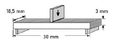
Fig. 8. Schematic of 3-point bending test specimen [12]
3.2 Adhesion between 3d-printed functions and the PEEK/carbon laminate
A 6-axis robot arm with a 3d-print head is used to print the functions on the substrate. This technology allows printing on large composite parts. Hot air guns have been added to the print head to bring sufficient thermal energy to ensure bonding.
Parameter sets leading to the best fusion between PEEK and PEI filaments have been determined. Thermal energy delivered by the hot air guns is a new process parameter considered in this experiment. Fracture resistance at the interface between 3d-printed functions and the composite substrate is measured with a DCB test (mode-I fracture test).
4 Discussion and conclusions
The influence of printing speed, printing chamber temperature and extrusion temperature on the thermal history at the interface between PEI filaments and a PEEK/carbon substrate has been demonstrated. It highlights the importance of controlling these process parameters to control the thermal history of the materials throughout the printing process. Experimental conditions were not adequate to create sufficient bonding between PEI and the composite substrate. Thermal gradient between filaments temperature when they are deposited, and printing chamber temperature was too important. More thermal energy to accelerate interdiffusion of the polymer macromolecular chains and a controlled cooling rate of the materials are needed.
To have information about the mobility of the polymer macromolecular chains, reptation time of PEEK and PEI are determined with rheological measurements. The aim is to compare these two polymers, knowing which one would have more facility to interdiffuse. A 3d-printer dedicated to high-performance polymers processing is used to study bonding quality inside PEI and PEEK parts. The influence of the process parameters on the porosity rate is determined with ANOVA. Parameter sets leading to the best bonding strength are finally identified with 3-point bending tests.
A 6-axis robot arm with a 3d-print head is used to print functions on large composite parts and to determine in which conditions adhesion between the two elements is maximized. In the study of Meng et al., an additional laser source is used during the printing process to bring more thermal energy to the materials and ameliorate bonding (see Figure 2) [5]. In our case, hot air guns are used to get closer to the melting temperature of the materials and accelerate macromolecular chains diffusion.
The main goal is to add functions with additive manufacturing on a PEEK/carbon composite part manufactured with AFP. High-performance polymers are very challenging to 3d-print and this study gives information about how printing parameters affect the mechanical properties of the final part. Thermal history of the materials is the key parameter to control throughout the process to enhance bonding. Process temperatures and cooling conditions need to be carefully controlled to minimize thermal gradient. Increasing interface temperature up to melting temperature promotes coalescence and healing. Too high temperature can cause material degradation and final part geometry distortion. This work provides the methodology to obtain a process window where parameters have been optimized to maximize the bonding strength without compromising the quality of the printed function. The experimental study will be coupled with modeling of the heat transfers at the interface between the substrate and the first printed layer and modeling of the coalescence phenomenon between adjacent filaments.
Acknowledgements
Financial supports from Communauté d’Agglomération du Pays Basque (CAPB) fund are gratefully acknowledged. The authors would like to thank the teachers-researchers, research engineers, engineers and technical supports of ESTIA Institute of Technologies and of technology platform Compositadour for their excellent assistance in this work.
