1 Introduction
The spread of additive manufacturing (AM) in industry is progressing. Particularly, large growth is taking place in aeronautical and medical applications [1]. 65% of industrial companies already have experience with AM [2]. AM opens up various alternatives to conventional manufacturing processes. Consistently, professional technical reports such as Wohler [3] likewise strategic management and consulting companies estimate the annual growth of the AM sector to be over 10 % [2,4–6]. 72 % of AM using companies in the industry have experience with processing polymers [2]. In the future, the growth of the polymer sector within AM is considered to be particularly high. In 2015, polymer-based AM accounted for over 80 % of the AM market, but still 0.04 % of the overall manufacturing market. This is predicted to increase to approximately one percent by 2035, which is equal to a growth of 2500 %. [5] One commonly used process is an extrusion-based technique, namely the Fused Filament Fabrication (FFF). Approximately 45 % of the currently used machines Apply the FFF method and the number of application is not expected to decrease within the next years [4]. These positive forecasts are based on the above-average growth in the use of FFF for the production of final parts. However, the certification of printed products is a challenging task. This is attributed to instabilities in the processing that lead to poor properties of the produced parts. Therefore, the certifiability of AM parts is an acute and primary task. Other research groups have mentioned the standardization and certifiability as a primary issue. [7–10] The properties of additively manufactured parts subject to standardization can be divided in the following main categories: Anisotropy [11,12], porosity [13,14], geometric fidelity [15,16], surface quality [17,18], repeatability [19] and residual stresses [20].
As early as 2009, experts recognized the need for standardization and therefore scheduled a roadmap for the coming 10 to 12 years [21]. In 2019, Sacco et al. [22] reviewed 45 standards. None of these current standards is applicable to AM. In particular, the influence of process parameters on part quality is not sufficiently known. This prevents a significant development of standards. Vora et al. [23] take a further and include the measurement methods for quality control in their considerations. Moroni et al. [9] describe the efforts of institutes such as ISO to cover the need for standardization. Nevertheless, none of the standardization approaches meets all the demands. Among other factors, this leads to the discrepancy between the roadmap and the status of certifications. Due to this gap, the technologies remain behind the economic expectations. Therefore, economic analyzes have highlighted the development of globally defined standards as a top priority [24]. Another complicating factor are the limiting certification guidelines in certain business sectors. E.g., in aerospace the modification of material composition in order to fulfil the requirements is not permitted. Thus, the process is adapted. However, even these adaptations are only permissible to a limited degree. [25] Such procedures are known from aviation. Due to this overall complexity, certification processes are particularly time-consuming. Research groups are looking for alternative methods. Seifei et al. [26] propose model-based qualification approaches. Other strategies pursue the use of in-situ measurements [27]. Charles et al. [28] even point out the use of in-situ measurement paired with artificial intelligence to validate the process. Nevertheless, Tofail et al. [29] highlight the difficulties of making the necessary adjustments to the measurement methods for different types of machines. The main challenges mentioned have not yet been overcome. Hence, no general standards have been addressed. This way the application possibilities of all mentioned concepts are limited.
To meet these demands, the business ecosystems have so far been adapted. This means that the machine architecture and supply chain are restricted. [30,31] Individual components or segments are not interchangeable. For this reason, the commercialized supply chain in businesses is a closed ecosystem [32]. In these systems, the material, its storage as well as the process parameters and conditions are specified without the possibility of adaptation. This has made it possible for the Stratasys Inc. to generate certifications for blends of polyetherimide (PEI) and polycarbonate (PC) in the automotive, medical and aerospace sectors [33]. For this material class (also called ULTEM 9085), the manufacturer specifies 33 to 47 MPa for the tensile strength, depending on the print orientation [34]. Depending on the orientation, these mechanical properties are only between 46.5 and 85.8 of those of samples from an injection molding process [11]. These results show the unsolved, arising issue of anisotropy even in a certified system. The current standard in the AM sector is still the closed system approach [30,35]. This closed (also known as "black box" [36]) approach enables reproducibility and thus consistent quality, but does not cope with the aforementioned difficulties in the process. In addition, the individual elements of the supply chain are not interchangeable or combinable in a closed architecture. Due to the unsolved issues, the result is product-based and not process-based, i.e. the manufactured result of the same process does not remain constant as soon as a different arrangement of the product or a slight change in the machine properties is applied. Hence, no global standards can be developed based on this concept. Figure 1 (left) presents a product-based and closed supply chain. The US National Institute of Standards and Technology officially noted these limitations in 2016 and devised an independent procedure to overcome them [36]. This starts with a complete breakdown of the interactions of process parameters and part quality. Only thereafter, the relevant parameters can be determined. They are necessary to be able to build global standards in an open system with increasing complexity. This need has also been deduced by other research groups [27,30,31]. Only such open architectures make it possible to exchange the individual elements in the supply chain. In addition, product-independent process certification is possible for the first time. Figure 1 (middle) illustrates this. The Boston Consulting Group discusses the advantages of such open systems from an economic point of view [35]. The open system provides access to additional paths in the supply chain as it allows flexible combination and substitution of the elements (see Figure 1 (middle)). Verboeket et al. [37], for example, draw the same conclusion. Savolainen et al. [38] extend the scope of consideration to entire ecosystems.
Based on the demands, a methodical analysis of the extrusion process has to be carried out. This can point out elementary relationships between the process parameters and the part quality. Based on these relationships, the relevant questions for further research work has to be identified. Thus, the basic knowledge for standardization can be created.
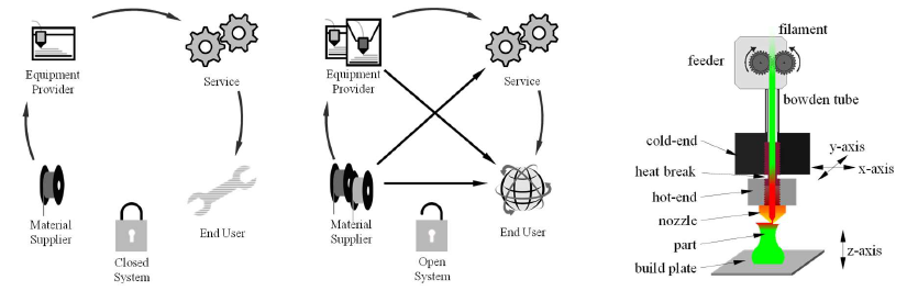
Figure 1: Commercialized Supply Chains of Additive Manufacturing (left and middle) and Fused Filament Fabrication (right)
2 Extrusion Process in the Context of a Methodological Investigation
The FFF is a sub-process of the material extrusion (defined by ISO/ASTM 52900), which uses a round filament as feedstock material (mostly with a diameter of 1,75 mm). The feeder feeds this filament with at least one driven gear in the print head. Printers for processing of high performance materials like poly(ether ether ketone) (PEEK) normally include a heated print chamber. Therefore, the feeder is located outside of this chamber. It is connected with the print head through a flexible and temperature resistant bowden tube. The backend of the print head is also called cold-end. An active cooling provides the stability of the filament. Through the so-called heat-break the material is entering the nozzle. The nozzle is a part of the hot-end, which is separated through the heat-break from the cold-end. In this area, the material changes into the molten state and is pushed out of the nozzle tip. With a relative movement between the print head and a build plate, this molten material forms the part. Figure 1 (right) illustrates this arrangement.
Methodical investigations such as OFD, FMEA, SWOT or TRIZ are primarily used in product development. Thus, the process development itself is not considered. [39] For this reason, AM is mainly used within such method bundles to improve the classical manufacturing. [40] Applying FMEA in product design, Yusoff et al. [41] demonstrated an improved quality of the printed parts. The manufacturing conditions of FFF are included but not considered across the design aspects of the product. Quanjin et al. [42] use a SWOT analyzis on product level, as in Yusoff et al. [41]. More detailed process characteristics are not considered but only their influence on the product. Only Bas et al. [43] includes the parameters of the extrusion process by using a FTA. Here, the process-related events are linked to the part quality by a fault tree. "Printing too fast" is an example of a macroscopic parameter. The physical interactions within the extrusion process are not examined and thus not the cause of the quality deviations. In a literature review by Moltyl et al. [44], 14 out of 115 potential papers could be identified with a combination of TRIZ and AM. TRIZ mainly supports the generation of concepts and solutions. However, TRIZ is used in the study of design for AM [44]. The TRIZ method bundle offers various sub-methods for differently oriented considerations. Güner et al. [45] investigated the possible use and frequencies of application of these sub-methods. The third most frequently used sub-method is the "functional analysis". Among other advantages, this sub-method offers a detailed technical view of processes. For example, a technical orientation of the analysis was performed by Wang et al. [46] using the example of material jetting.
3 TRIZ Methodology
In 1946 Genrich Saulowitsch Althuller started the research work for TRIZ [47]. This acronym stands for „теория решения изобретательских задач“, which translates to "theory of inventive problem solving" [48]. Altshuller studied more than 40.000 patents to investigate the evolution of technical systems [49]. Altshuller divided the innovation process into the following phases: analysis of tasks, solving of challenges and selection of solution concepts [49]. Authors like Orloff [50] further develop the TRIZ method under the name Modern TRIZ in a practical oriented way. Moreover, the principles are formulated for specific research groups such as engineers [51]. These formulations are able to analyze systems on a component-level and model problems of interactions to provide solutions [52].
The functional analysis (FA) is a common tool from the first phase, the analysis of tasks. The FA consists of several consecutive steps. They include the analysis of the components, the interaction between them and the modelling of the overall system. Thus, the FA offers opportunities to investigate the tasks: problem understanding, structuring, goal clarification as well as generating solution ideas [39]. These steps of the FA are known as the component analysis (CA), interaction analysis (IA) and functional modelling (FM). For a specific use from an engineering point of view, Münzeberg et al. [53,54] had a closer look in the analyzing steps to improve technical systems. The authors illustrate the possibility of using the FA to decompose a system systematically. Based on these analyzes, undesired interactions or quality features in the final product can be classified. The final visualization highlights the potential for further process development.
4 Investigation of the Fused Filament Fabrication with Functional Analysis
Several authors have already analyzed the AM with other methods (see section 2). The level of investigation is general. The presented FA enable investigations on a detailed technical level. The Investigation is applied to the general FFF depicted in Figure 1 (right). For a further development of the FFF process, the part quality is the matter of interest.
4.1 Component and Interaction Analysis
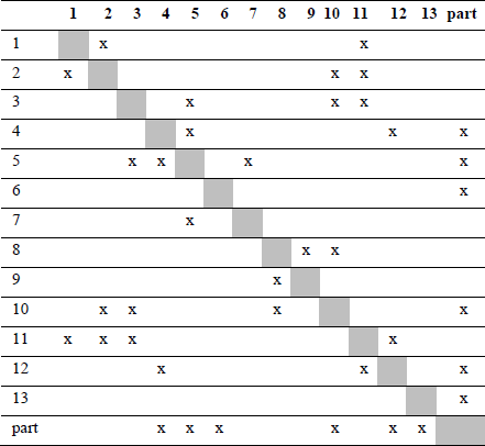
The analysis starts with the identification of the individual components. There are three categories of components: target, super and ordinary. The part is an indicator for quality and thereby the only target component. The environment in the build chamber is the only super components that is considered for this analysis. The schematic process flow in Figure 1 (right) shows the ordinary components. The process is extended with additional ordinary components such as slicing program. These and components such as the polymer melt add a higher resolution to the process. Except for the target component (the part), the other components are assigned the following numbers: 1 feeder, 2 bowden tube, 3 heat break, 4 nozzle, 5 hot-end, 6 build plate, 7 heater, 8 kinematic/motors, 9 slicing program, 10 print head/ cold end, 11 filament, 12 polymer melt, 13 environment.
Interaction analysis captures the multiple possible interactions between the components. A cross (x) marks an interaction in Table 1. The direction of the interaction is not indicated. Thereby, the table has a symmetrical form. Only the subsequent step captures the interaction direction. The direct interaction partners are of primary interest for the analysis of the target component.
Table 1: Interaction Table
4.2 Functional Modeling
The final step is the modeling of the overall system with its interactions. The goal of modeling is to define the understanding and illustration of functional interactions. FM captures the directions of interactions and transforms them into functions between components. By definition, an action changes the specific state of a component and is represented in FM as a function. Such as the interaction of the environment (super component) and the part (target component) which leads to the action/function "cool". Based on this principle, evaluating the functions is the next step. Red arrows mark the identified undesirable functions. In general, they are starting points for improvements. Figure 2 shows the graphical outcome of the FM. The component categories (target c., super c. and component) have their individual graphical representation. The connection between the components via functions forms the technical system.
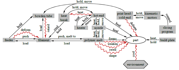
Figure 2: TRIZ Function Model of FFF
5 Undesirable Functions from Functional Analysis and Research Gaps
The undesirable functions highlights critical areas in the process. These areas cause insufficient part quality. Therefore, the undesirable functions with direct connection to the part are of particular interest. Figure 2 shows the five identified critical functions deform, cool, weaken, swell and shape. These functions require detailed research.
5.1 Deform
In the FFF, a kinematic system ensures a relative movement between the print head and the build plate. Due to the manufacturing tolerances, this mechanism contains a backlash. This leads to deviations between the movement generated by the code and the actual desired movement. The consequence is an undesirable deformation of the part. The FA models this as "deform". The function modeling in Figure 2 represents the general FFF from section 2. In this design, the print head moves in the x/y plane and is subject to deformation.
There is no direct connection between the print head/cold-end and the hot-end. Therefore, the deformation affects the part almost directly. There are uninterrupted nozzle systems that are particularly designed for processing high-temperature polymers. In designs for processing high-temperature polymers, uninterrupted nozzle systems exist. These designs have already been discussed in other examples [55]. This holistic approach changes the design of the FA. An adapted model is shown in Figure 3 (left). The mode of transmission or action of the deformation changes according to the new modeling.
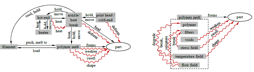
Figure 3: Adjusted Function Model for Uninterrupted Nozzle Designs (left) and Decomposition of Polymer Melt (right)
A geometric discrepancy between printed parts and their initial data has been sufficiently analyzed [56,57]. Further causal research does not exist. In principle, the total deviation is a superposition of the kinematic tolerance in the form of a deformation and the materialrelated shrinkage during solidification and cooling. An optical measurement method enables separate examination of the deformation by the positional accuracy of the print head. The setup allows studies of positional accuracy and repeatability at different traverse speeds on a Prusa MK2S with the triangulation sensor ILD 1420-25 from Micro-Epsilon. In this investigation, the effect of the influence of a multiaxis movement can be examined. The inherent maximum deviation of the measuring system is at 0.023 mm. The maximum deviation of the position accuracy is 0.124 mm. For correct printing, however, the absolute position accuracy is less relevant than the position repeatability. The fluctuation of the repeatability as well as the maximum deviation is below the mentioned measuring accuracy in the setup. The deviations in total position accuracy are as expected and the repeatability is low. Shrinkage during solidification depends on the material. In the case of semi-crystalline polymers, shrinkage due to crystallization occurs in addition to the thermal shrinkage. When cooled from 400 °C to room temperature, the shrinkage of PEEK is in the range of 18 % [58]. An Apium HPP 155 was used to print a block (60x7x20 mm) of Victrex 450G to determine the overall variation of geometric deviation. The kinematic of this printer has at least the quality of the Prusa. Subsequently, the printed part was examined for geometric fidelity to the initial model using a GOM ATOS Triple.
The maximum geometric deviation of the part is over four times greater than the tolerance of the kinematics for a comparable printer, even when all measurement tolerances are taken into account. For more complex components, deviations of more than 1 mm can be determined. The use of support structures further increases the deviation.
The geometric deviation is a function of the height of the printed block and reaches its maximum at the halfway of the component height with -0,67 mm. Both the magnitude and the height dependence lead to the conclusion that the kinematic tolerance is of secondary importance. This holds true at least when processing high-temperature materials such as PEEK. Instead, the material behavior during solidification comes into focus. Therefore, it has to explained under what conditions the material is solidified. The printing environment predominantly determines these conditions.
5.2 Cool
The FFF extrudes the melt into the air-filled build chamber and specifically onto a build plate. Generally, this build plate is heated. Depending on the design, the build plate or even the entire build space can be heated up. In some systems for processing high-temperature materials such as PEEK, surrounding temperature conditions are up to 250 °C or even 300 °C after modifications. The extrusion temperature for PEEK is at least above 400 °C and in general above 450 °C. As a result, the temperature delta directly at the extrusion exit is greater than 100 °C. This results in the "cool" function that is exerted directly on the target component by the super component "environment". Polymers, unlike metals, have relatively low thermal conductivity (PEEK for example has a conductivity of 0.2494 J/kg C [59]). The heat storage due to low thermal conduction of the printed material counteracts the cooling by the environment. To depict the cooling behavior an infrared camera focus the material on the top layer of the polymer block during the printing time. At the start of the printing process, the temperature of the first material layer is 117.9 °C. This corresponds to the pretempering of the build plate. The temperature of the top extrusion layer increases to 180.2 °C in the end of the printing process as the material of this layer is just freshly deposited. Another investigation focus on asymmetric temperature distribution over the height. A thermal differences of more than 50 °C can be measured. This highlights a solidification and cooling process that depends on the geometry of the component. The temperature gradient directly determines the layer bonding, as well as the degree of crystallization in the part. Several research groups investigated and characterized the bonding [60–63]. The same applies to the crystallinity in printed structures [64–66]. For correct design and appropriate use of printed component, these material properties must be quantifiable before printing parts. For this purpose, Turner et al. [67] sorted the FFF thermal process simulation by size scale, solution approach, and printing material. Other research groups have developed studies and models to quantify the above mentioned material properties [68–72]. During validation, non-negligible deviations are measured [67,73]. No reliable simulation is currently available. The use of high-performance polymers even increases the deviations in validation.
5.3 Polymer Related Functions
In addition to the functions investigated so far, the polymer melt itself causes crucial functions. The undesirable ones are weaken, swell and shape. The melt consists of several phases. The phases interact with each other and affect the part through the functions. The further decomposition of the polymer melt allows a detailed investigation. The components are the polymer, reinforcing fibers and voids. In addition, the melt consists of three physical fields. These are the stress, temperature and flow field. Figure 3 (right) illustrates the undesirable interactions between the individual components.
5.3.1 Weaken
Among other things, pores weaken the parts. Various research groups have already studied the appearance of pores in printed parts. Mainly, macroscopic pores and fiber condition are considered. Their formation is assumed to be process-induced, however, this has not been further investigated. [74–76] Only Tekinalp et al. [77] categorize the pores into inter- and inner bead pores. Stepashkin et al. [78] apply this classification and extend it with regard to the inner pores. Furthermore, Stepashkin et al. [78] introduce "thermal stresses" and "lack of impregnation" explanatory approaches. Papon et al. [14] and Sánchez et al. [79] classify pores in printed parts in this context. Up to four different pore types are defined. The feedstock material is not included in these considerations. The elementary components of the melt directly depend on the feedstock material. Therefore, Ning et al. [80] expand the investigations to their own produced fiber-reinforced filaments. For the first time, a pore category for "gas evoluted pores" is introduced, which is already created during filament production.
Berretta et al. [81] intensify the investigations on the feedstock material by using a micro-CT. The results obtained cannot identify any obvious pores in the reinforced feedstock material. Only Lin et al. [82] produced micrographs of the carbon fiber reinforced PEEK feedstock material. Lin et al. [82] discuss a large number of pores as well as a qualitative correlation between the fiber orientation and the manufacturing process of the feedstock material. None of the mentioned research groups gives a deeper characterization of the feedstock material or a quantitative analysis. Initial characterization approaches are offered by Sommacal et al. [83,84]. In the results, a variation in the orientation of the fibers along the longitudinal axis is recognizable. In addition, a void content of more than 10 % and a process-related arrangement of the voids is detectable. Further quantitative investigations of the feedstock material are unknown so far. Therefore, the correlations between the parameters of the feedstock material and the quality of the part are still largely undisclosed.
5.3.2 Swell
The amount of the material flow determines the extrusion process. On the other hand, the pressure difference between the inside of the nozzle and the environment defines the conditions under which the material exits the nozzle. The pressure difference can cause effects such as swelling of the polymer at the exit point of the extrusion process [85]. However, the extent of the effects of the pressure difference are only partially known. According to the FA, the stress field is the associated physical field. The stress field inside the die is therefore of particular significance. To understand the stress field and its effects, a more detailed understanding of the polymer melt in case of pressure action is necessary. The feeding force of the filament determines the internal nozzle pressure. The power of the feeder motor set this pressure. Initial investigations are only considering the motor and its feeding force [86]. Further work uses a separate measurement by using a universal testing machine to determine the feeding behavior of the feeder [87]. This way, no direct measurement or online monitoring of the process is possible. By utilizing vibration sensors Tlegenov et al. [88] and Li et al. [89] make the online monitoring of the process feasible. The applied sensor is located on the print head and can be calibrated to the feeding force by coupling it to the print head. The measurements are not quantitative values of the feeding force. Only with test setups such as those of Go et al. [90] and Nienhaus et al. [91] direct measurement data can be determined during extrusion. They both use a load cell directly at the print head without investigations with a bowden tube. Matschinski et al. [92] are the first research group taking all these aspects into account. Investigations about high-performance materials and pressure value fluctuations over the time are still missing. These are essential to ensure a constant extrusion quality.
5.3.3 Shape
The bonding between the material layers is a welding process [93,94]. The reputation mechanism determines this welding [67,95]. An increase in the exit temperature favors this mechanism and the resulting fusion bond [96]. Therefore, the extrusion temperature at the exit point is of particular importance, in addition to the mechanism of cooling from section 5.2. The stress field from section 5.3.2 depends on the thermal properties of the melt parallel to those described above. Thermal properties include the melt properties such as viscosity [97]. Hence, Duty et al. [98] have applied a viscoelastic model. This copes with requirements for pressure-driven flow, bead formation, bead functionality, and component-level functionality. The requirements shall enable to make predictions about the printability of a material. Yan et al. [99] already use a combination of simulated temperature distribution and the viscosity-temperature relationship for optimized process planning. For extrusion-based processes, Osswald et al. [100] give a modelling approach. These studies investigate and find out the influence of the temperature field on the shaping of the mechanical properties as well as on the quality of the part. The undesired decrease of the mechanical properties is represented by the “shape” function in the FA. This makes a detailed measurement of the temperature inside the nozzle and over the entire heating length necessary. The barrel of the nozzle has normally an inner diameter of 2 mm. The diameter of the feedstock material is 1.75 mm. This scale makes the integration of the sensor system into the process complicated. To close this lack, Pollard et al. [101] embed additional thermistors and a thermal camera. To get an even better understanding, Anderegg et al. [102] modify the hot-end. To use these methods of investigations, it is necessary to modify the process and therewith the process conditions. Moreover, these methods do not fulfill the requirements for the application in high temperature facilities. With fiber optical sensors, Canning et al. [103] firstly present a measuring system small enough to be integrated in the FFF. Nevertheless, there is still a research gap in evaluation of the inner temperature and therewith in measuring approaches to provide these values.
5.3.4 Degrade & Break, Orientate
The detailed disassembly of the polymer melt in Figure 3 (right) reveals a further physical field, namely the flow field. This field describes the polymer flow inside the nozzle. Form mechanical perspective, the behavior of the flow follows the boundary conditions of a Stokes-Flow. This way, the shape of the flow field is determined by the inner surface and the nozzle geometry. The resulting shape defines the mechanical load acting on the melt. The consequence can be a shortening of the polymer chains and thus a degradation of the polymer. Moreover, it can lead to unintended fiber formations. More detailed investigations are given by several research groups [55,104–107]. However, a quantitative analysis of the fiber orientation and length is still missing.
6 Conclusion and Outlook
AM is one of the largest growing Manufacturing sectors. Nevertheless, many scientific studies have already identified far-reaching unresolved challenges in the AM process. This is one of the reasons that prevents further developments on an industrial level. Therefore, industrial implementation falls short of their expectations. Major standards development institutes have recognized this shortcoming. In contrast to previous practices, a more detailed examination of the process itself is required. To achieve this, other studies have tried to use analyzes of the major method bundles such as OFD, FMEA, SWOT or TRIZ. However, the process itself has not been sufficiently involved in this context.
The present work analyses the AM process by the means of the functional analysis according to TRIZ. The functional analysis enables a complete fragmentation of the technical system. This reveals the complex coherences. For studying the quality, the part is the target component. Of particular interest are the undesirable functions influencing the target component. These are deform, cool, weaken, swell, shape.
Printed parts have a geometric deviation. This is related to the fluctuations in the movement system. The FA illustrates this with the function of deformation. Yet a closer look at the deformations reveals that their consequences on the part are rather minor. The geometric deviation depends on the solidification. The solidification procedure is defined by the surrounding conditions. The FA illustrates this with the function of cooling. This function underlies sophisticated boundary conditions. This leads to the research question:
How can the boundary conditions and progress of the solidification in the printing chamber be characterized?
The polymer melt itself induces the remaining functions from the FA. Further breakdown of the polymer melt yields three subcomponents and three relevant physical fields. According to the analysis, voids mainly cause the weakening of the printed components. Looking at the root cause, brings the feedstock material into the center of the considerations. Existing and new measurement methods of this material reveal a multi-layered composition. The phase compositions as well as arrangements within the material are still unknown. The ongoing question about this is:
How to characterize the feedstock material?
The primary parameter of an extrusion is the pressure difference between the inside of the nozzle and the environment. This defines the material outflow. Undesirable side effects may occur, such as swelling of the material after the nozzle or general fluctuations in the amount of output. The correlations between process parameters and these appearances are not evident. The research focus for overcoming this issue is in the area of pressure distribution within the nozzle. The associated question is:
What is the impact of the feeding and output mechanism?
The extruded material is layered on each other. A welding mechanism ensures the bond between the deposited layers of material. This means temperature is the primary parameter for the part performance. The mechanism that shapes the material properties can lead to poor values. Measuring temperature and flow characteristics is challenging due to the small scale of the FFF machine. The unsolved research aspect is:
What is the characteristic of the temperature field inside the nozzle?
Answering this research question will close some major gaps in the process of understanding the FFF. Based on the results, further process stability can be achieved. This makes the creation of initial standardizations and guidelines possible. This work contributes to the creation of general certifications for AM. Nevertheless, undesirable interactions within the melt must be fully explored in order to implement verifiable certifications. E.g., this includes the influence of the flow field. The mechanical load during processing generates this flow field inside the nozzle. This field interacts with the other sub-components of the polymer melt. This is directly influenced by the design of the nozzle geometry. Thus, the geometry influences the mechanical impact on the melt. An adverse geometry can degrade the polymer and break the fibers. It is recommended to investigate these effects by testing the entire components. With an improved process, an enhanced understanding and increased stability of the process, it is possible to generate new criteria for the AM process. These criteria will address the additional influences such as the impact of the flow field as well as the improvements by finding answers to the research questions mentioned above. This proposes the establishment of reliable regulations in the field of testing at industrial level.
Acknowledgements
The authors thankfully acknowledge the funding at TUM provided by the German Federal Ministry for Economic Affairs and Energy under the scheme “ZIM: Zentrales Innovationsprogramm Mittelstand” – funding code: ZF4004316WO9 and the Bavarian State Ministry of Science and Art under the project “Facilities of the Bavarian International Campus Aerospace and Security”.
The authors thankfully acknowledge Silvano Sommacal and Paul Compston of the Australian National University for their research in computed tomography, which has been directly integrated into this paper.
The authors also thankfully acknowledge the Airbus Group, BMW Group and Ensinger GmbH for support with facility, analyzing equipment and processing material.
