1.Introduction
The realization of a given physical object requires the building of specific die geometries made by means of CNC machine tools able to follow well defined programs in order to get the desired shape and geometry characterized sometimes by a complex mathematical description [1]. In such a way it is possible to obtain very complex die cavity shapes uploading the information on the machine control unit. However, such procedure requires the use of the defined fixture, of the required part program and of the required maintenance due to wear problems [2]. In order to avoid all of the already reported variables and phases, high consumption of materials, heavy machining operations and related costs, the additive manufacturing techniques in the realization of polymer objects can be involved instead or in conjunction with injection molding [3].
The additive manufacturing technologies are very well known in the field of manufacturing systems as layer by layer techniques since the three dimensional product is realized by the deposition or treatment of one layer of hundredths of microns or less each time until the entire geometry is realized and used in different fields [3-8]. That kind of building requires the digital information be implemented by the Standard Triangulation Language in which all of the geometry information is approximated by a very high number of triangles described by the position of their nodes and of their normals [8 -11]. The three dimensional surface obtained in that way is in general sliced in order to get in plane profile of each layer to be realized each time. Further methods are available in literature, but strictly dependent on the compatibility among the softwares and among the machines to describe the complex shapes starting from the surface information supplied in terms of control nodes [1,12-15]. In fact, the control points or nodes when considered in a clear way can be effectively used to generate the desired surface in particular for CNC processing [5, 14-16]. If not, the meshing technique based on the triangulation is very useful because the list of nodes and the normal position can be better readable by different softwares and neglects some other not required information that are very important only in the initial phase when geometry and manufacturing constraints need to be defined.
Among the different additive manufacturing technologies the poly-jet system is based on the photo-polymerization of monomers ejected from one or different jetting devices [6-7]. In particular, the quality of the realized physical model is dependent on the technology used firstly and on the process parameters chosen. In general it is potentially characterized by the lowest thickness layer that, among other variables affecting the surface quality, is particularly important in defining the continuity and the smoothness of the surface. Due to these characteristics, the obtaining of the surface requirements is also depending on other factors such as the material.
Instead, the Fused Deposition modelling is the most known technology in the field due to the simple mechanism of deposition characterized by the extrusion of a filament into a heated chamber in which the temperature can reach 250-300 °C depending on the material. Immediately after the deposition due to the contact with layer previously deposited and to the lower temperature the filament tends to be solidified [16-20]. In such a way of course the maximum thickness of the layer can in general reach values higher than those obtained with the technology shown before, particularly when compact three-dimensional printers are used for testing purposes.
In general the obtaining of a given workpiece or prototype requires a procedure characterized by some iterations. In particular, the most rapid way to get the prototype can be obtained choosing the fastest one or that characterized by low or minimum cost in terms of energy consumption, time and material. Some materials such as polyamide [21] and PLA [17] can be very useful for SLS and FDM.
The surface quality of a realized physical object can be improved with post-treatment, even if the action on the input file represents the way to get a similar result [22-25], notwithstanding the proper characteristics of the process. The possibility offered by such techniques in reproducing shapes or part of shapes by the information got by 3D shape digital detection is still under investigation due to the elevated number of variables affecting the detection stage, the digital data computing and the realization of the object with given technology with related given parameters and materials.
The present paper aims at proposing a methodology based on the use of digital geometrical data to reproduce a complex shape by additive manufacturing. Initially the real potential in getting the complex geometry was tested using a poly-jet system based on UV rays for polymerization. The file generated by the 3D scanning of the high quality physical object already realized is updated in different ways in order to get after few iterations a rebuilt geometry using the FDM techniques. Useful for comparison between the shape obtained by original digital data and those got by the scanning in the prototyping stage. In particular, the different digital parameters are varied in the CAD environment and the results and the comparison with the original physical object are made by a compact FDM machine. The details are reported in the following.
2.Experiments
2.1 Methodologies
The methodology is reported in Fig. 1 in which the path followed in the building of the physical object using two different additive manufacturing technologies with related STL generation by three-dimensional surface scanning of the best model got by poly-jet system can be seen. The detailed characteristics are reported in the same figure. The physical objects realized by the original CAD data are compared with those generated by the information of the 3D SCANNER. Such information is then updated in order to get an input file able to produce directly the physical object with shape and geometry as similar as possible to that obtained by the original CAD information.
2.2 Digital data computing and experiment procedures
In detail the CAD information [11] consisting of a surface built on two main B-splines obtained by six control points each is reported into STL file. Initially, after slicing and supporting generation the physical object characterized by the described complex shape is built using different additive manufacturing technologies. One object is realized by a poly-jet system using a UV sensitive photo-polymer. It is characterized by a jet system from which the liquid photo-polymer is ejected and immediately solidified by the UV light array while the head is following the trajectory given by the CNC. The layer thickness was of about 0.014 mm. The second physical object is realized by the Fused Deposition Modeling technology in which a filament of polyamide material is deposited layer by layer at given temperature and solidified by the ventilated air. The layer thickness used was of about 0.26 mm. The temperature at the extruder was 250 °C with the working volume at 75°C. The last physical model is realized by a Fused Deposition Modeling compact printer in which the PLA material is deposited with a layer of 0.28 mm at 215°C in room temperature calm air. The physical object realized got different characteristics in terms of global shape (main configuration of the object), of global geometry (particulars of the plane and round parts with respect to their dimensions), of staircase (effect due to the overlapping layers to each other) and of waviness (low frequency ondulation due to the characteristics of the process mainly dependent on expansion and shrinkage phenomena taking place during building).
The physical objects are compared to each other in order to put in evidence the main differences arose. The photo-polymerized model was scanned by a 3D SCANNER to get the digital information. That was processed in order to get comparisons with the original ones obtained by the CAD model. The original model was characterized by a length, width and height respectively of 100 mm x 80 mm x 23.75 mm included a planar basis of 5 mm in thickness as observed in Fig. 2 [11].
The lack of quality in the detection of the physical object was mainly found in the curvature connecting the round part of the dome and the planar part of the basis. In such zone, the adjustment needs to be made in order to obtain a digital information able to reproduce a physical model as equal as possible to that obtained by the original CAD information reported in Fig.2.The complex geometry of the CAD model, in the STL configuration reported in the Fig. 3, can be described by approximating triangles shown in detail in Fig. 4. They have to respect the rule given as follows:

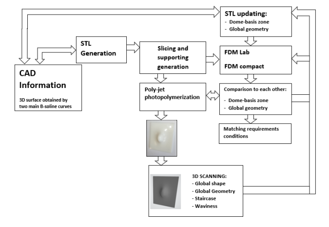 Fig. 1. Methodology.
In which the distance between the centroid of each triangle Ptriangle and the point of the surface Psurface under given conditions, in terms of number of triangles used in order to control the size of the generated file to be managed for the next phase of slicing and supporting realization, must be the minimum as possible.
The study was performed in terms of:
• The direct realization of the STL generated by the 3D SCANNER by two FDM machines
• The improvement of the 3D SCANNER digital model in terms of the improved triangulation density
• The improvement of the 3D SCANNER digital model in terms of the thickness basis correction up to 5.5 mm in order to include the critical zone represented by the dome-basis connection
• The improved triangulation density plus the basis correction up to 5.2 mm (linking the STL dome to the rebuilt thickness basis)
• The comparison between the physical models realized directly by the CAD and those produced after the improvements starting from the 3D SCANNER made mainly using the compact FDM machine.
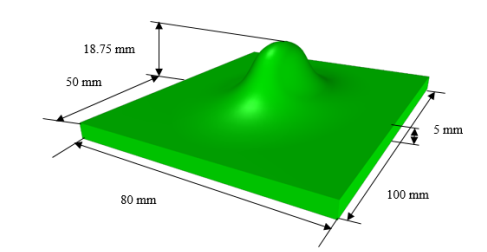
Fig. 2. CAD model.
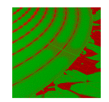 Fig. 3. Particular of STL standard.
 Fig. 4 Approximation by STL standard
3. Results and discussion
3.1 Digital data computing
The physical model realized with UV polymerization poly-jet 3D technology (Fig. 5a) got a dome height of about 23.78 mm, measured by a caliper. In that case the effect of the staircase is almost negligible. For that reason the surface was suitable for a non contact 3D SCANNER device detection. The obtained digital model is reported in Fig. 5b. The file in general requires a check in terms of the adjacency at the boundaries and of the positions of nodes describing each triangle as reported in previous Fig. 4. Such operation can reduce the error of some microns in adapting the triangles configuration. After that the file can be used as an input to the other machines in order to get other physical models.
3.2 Realization of the physical model by digital scanned data
The physical models were realized by the FDM technologies, that were a laboratory FDM stratasys and a compact FDM with related process parameters, machine performances and materials used. One made in the PLA material in the case of the compact 3D printer and the other one in Polyamide. These results using original CAD data are reported in Fig. 6. The surface appearance in terms of staircase and waviness can be observed. The staircase depending on the thickness of the layer used increases from the lowest staircase effect of the photo-polymerized physical model to the staircase of the Laboratory FDM machine and finally to the more elevated staircase of the compact FDM printer. For the last two models the effect of the staircase is much more evident than the waviness.
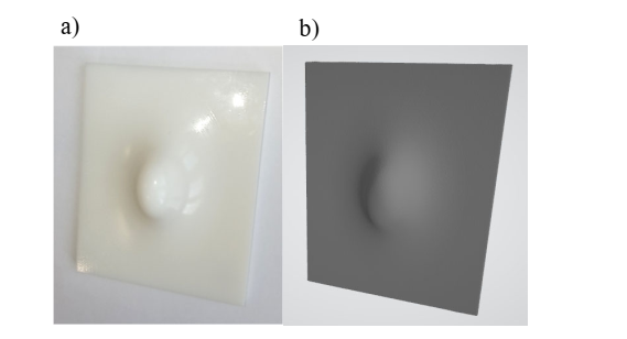 Fig. 5. Poly-jet photo-polymer physical model (a) and the related 3D scanned surface (b).
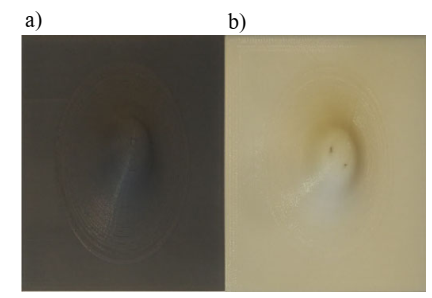 Fig. 6. Physical models realized by the compact FDM (a) and laboratory FDM Stratasys (b).
Taking a look what produced by the Laboratory FDM machine and by the compact FDM printer it is possible to observe the difference between the two models. The comparison between the models got by CAD and that realized by SCANNED digital data are reported in Fig.s 7 and 8 respectively for FDM Laboratory machine and for the FDM compact. Irregular boundaries at each layer are reproduced and in particular on the planar basis– dome connection surface of both objects realized by the digital data got by the non contact measurement, as well as some irregularities on the top of the planar basis. Such kind of phenomena are dependent on the input data that are directly supplied by means of STL standard got by the 3D SCANNER software to the software of both the FDM machines used. In Figures, the correct connection is reported by a continuous line while a the irregular or rebuilt one by a dashed line.
The improvement of the digital information is made by getting the cloud information into STL with a rebuilt refined meshing, i.e. an increased triangulation density. The related physical model is reported in Fig. 9a. But the same problem appears on the conjunction between the dome and the basis. A discontinuity arises. A further improvement was made imposing a rebuilding of the basis with a new thickness of 5.5 mm in the CAD environment and then translating it into the STL standard, Fig. 9b). This means that about two layers in the direction of the dome are lost, in order to reduce the problem at the connection between the planar and the curved part. In this way, the irregular discontinuity completely disappears but the procedure got a thickness basis to much higher than the original one. The final physical object is generated by the rebuilding of a basis of 5.2 mm in the CAD environment translated into the STL standard and added to the STL dome data with a refined triangulation. In the last case, the error with respect to the model got by the original digital data seems represented by a value that is less than one thickness layer (Fig. 9c).
That kind of tools is very useful in the prototyping phase and in fine tuning. Once solved the problem at the basis, the critical dimension to be considered is represented by the height of the dome. In particular, the laboratory FDM machine in which the original STL data are used got an height of 23.71 mm while when the input file used is that got by 3D SCANNER the height detected is 23.88 mm. The Table 1 and the Fig. 10 report the dome height values of the physical models obtained by the compact FDM printer for different conditions in terms of the input data.
In Fig. 11, the comparison between the model realized by original CAD information and the model realized after digital treated scanned data can be observed. The difference in the boundary dome-planar basis connection between the two models is reported in Fig. 12. It can be observed that the best situation on both the dome height and the connection between the dome and the planar basis is obtained for the condition 5 of the Table 1.
Such methodology is very useful when the acquired digital data by scanning methods need to be re-processed in the CAD environment in order to get a physical model also with other techniques [23-25]. The obtained results are in agreement and consistent with the study made by other authors who relate under some conditions the shape, the geometry, the staircase and waviness with stress concentration [26-28].
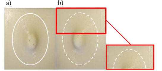
Fig. 7. Physical models realized by original data (a) and that by digital data got by the 3D SCANNER (b) for the LAB FDM printer.
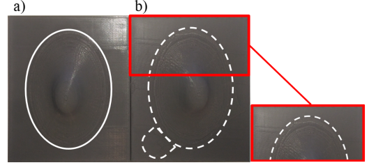 Fig. 8. Physical models realized by original data (a) and that by digital data got by the 3D SCANNER (b) for compact FDM printer.
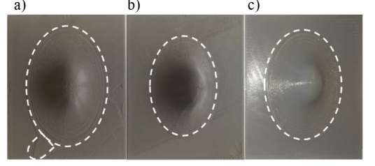 Fig. 9. Physical models realized by the digital 3D SCANNER data: directly by the STL with improved triangulation density (a), with the rebuilt thickness basis of 5.5 mm (b) and with rebuilt thickness basis of 5.2 mm (c).
Table 1 – Dome height of the physical objects realized by the compact FDM printer.
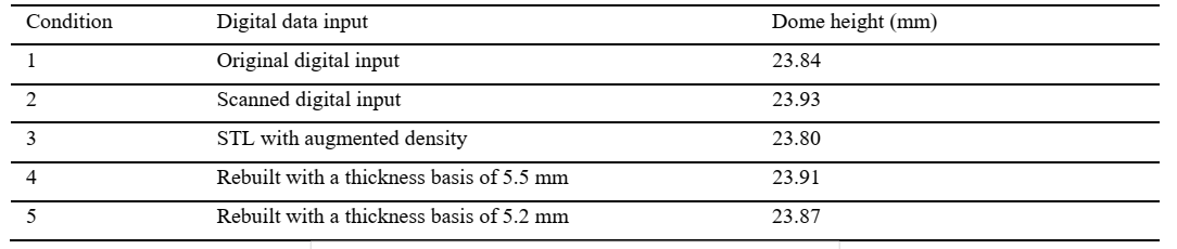
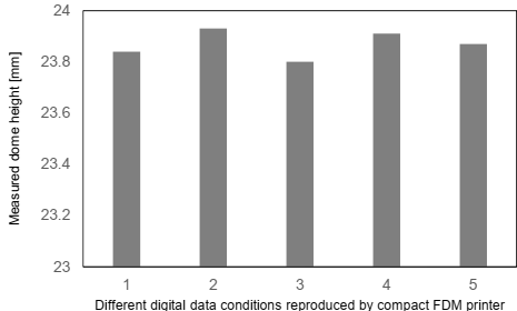
Fig. 10. Comparison between dome height values of physical models got by different digital data conditions.
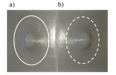 Fig. 11. Physical model realized directly by the original CAD information (a) and that realized in the condition 5 (b).
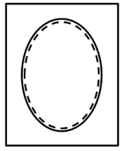 Fig. 12. Comparison between the boundaries of the dome of original CAD-STL file and that of condition 5.
Conclusions
The proposed methodology consists in the realization of FDM model by digital data obtained by three-dimensional SCANNING of a complex shape model given by the poly-jet photo-polymerization. Both the CAD and SCANNED digital data were used in order to realize models by a LAB FDM machine and by a compact FDM printer for prototyping purposes. Different techniques were used in the computer aided design environment for increasing the quality of the realized digital model from the dimensional and surface point of views. In particular:
• In all of the considered cases, independently of the machine and material used, the model got by the 3D SCANNER differs from that got by the original CAD information evidencing problems mainly in the connection between the dome and the basis and on the height of the dome
• The increase in the number triangles in the STL standard approximating the surface of the model do not resolve but put in evidence the continuity solution between the dome and the basis
• The increase in the thickness basis from original 5 mm to 5.2 mm solves the continuity solution in that zone with a loss in curvature and in a layer
• The comparison among the different five conditions reported in Table 1 got the choice of the last one in which a compromise between the objective height of the dome and the quality at the dome-planar basis connection is achieved.
That means that very compact 3D PRINTERS can be used in order to detect the improvements obtained in the re-building stage from digital data of models characterized by complex geometries. In general starting by the original information the dimensional and surface quality of the model can be affected by the material and PRINTER machine used.
