1 Introduction
The Single Point Incremental Forming (SPIF) process remains a hot topic researched in many institutions around the globe. Its apparent simplicity and high flexibility are due to its CNC controlled nature and generic tooling. SPIF only needs a spherical CNC-controlled tool and fixation of the sheet at its edges [1]. Its apparent simplicity however conceals highly complex deformation mechanisms, making process control a difficult challenge. The biggest challenges remain its low achievable accuracy and process limits [2]. Over the last 15-odd years, the relative freedom offered by the CNC controlled approach has spawned a plethora of different strategies that adjust the generating toolpaths in order to increase the process accuracy and/or process limits.
The use of multiple consecutive forming passes is a technique that has proven very effective in expanding the SPIF process limits. Using intermediate processing steps to form a workpiece leads to more efficient usage of the sheet material. Where the centermost part of the sheet often remains unprocessed, retaining its original thickness, multi-stage strategies modify the main deformation direction in the subsequent stages. A well-chosen selection of these intermediate stages can lead to more uniform thinning throughout the part [3]. The direct consequence is the increase of final sheet thickness in critical areas, possibly avoiding part failure. The effectiveness of a multi-stage technique with regards to the process limits is thus dictated by the uniformity of the final thickness distribution, influenced by both the shape and number of intermediate geometries produced [4].
Using a previously formed part as base for a subsequent step also leads to significant differences compared to conventional single-step SPIF with regards to part accuracy. The geometric rigidity of a previously formed workpiece is much higher than a flat blank, generally leading to higher forming forces and lower spring back, sometimes benefiting the accuracy. In other cases, the geometric rigidity can be detrimental to the final part quality. If intermediate shapes contain geometric details with high curvature that are not present in subsequent geometries, these can prove hard to fully remove. When forming truncated conical or pyramidical geometries, the bottom edge is such a difficult geometry, often leading to stepped features due to rigid body motion of the part bottom when using multi-stage forming [5]. This behavior can however be taken advantage of through the use of a simultaneous Double Sided Incremental Forming (DSIF) strategy [6].
A final issue for the use of multi-stage forming strategies is generalizability. The fact that most research regarding these types of strategies uses simple symmetrical workpieces with constant wall angles is no coincidence. Barring the fact that truncated cones and pyramids provide good demonstrators for new techniques and provide a good basis for comparison, they also make designing the intermediate shapes a relatively simple task, often coupled to determining a desired intermediate wall angle and stepover. It is however less evident and often even impossible to translate these strategies to complex freeform geometries with continuously variable wall angles.
In this work, harmonic decomposition [7] is used to overcome this last issue, since the technique makes it rather straightforward to generate an intermediate shape for freeform workpiece geometries. The workpiece is generated in three subsequent SPIF steps: a first step creates the intermediate shapes, while two finishing steps are needed to deform this shape to the desired final shape. One of these finishing steps needs to be a back-drawing step [8-9], where the sheet is processed from the other side after having flipped the clamping rig. Different production sequences and toolpath methodologies are devised, taking advantage of the properties of the harmonic decomposition method. The two benefits of using multi-stage strategies, improved accuracy and improved part thickness uniformity, are studied for these sequences method.
2 Automatically generating intermediate shapes using Manifold Harmonics
2.1 Intermediate shape generation
Harmonic decomposition describes a 3D surface as a sum of a number of oscillatory component surfaces, manifold harmonics. Just like the Fourier transform uses the sine and cosine functions to decompose a 2D signal, harmonic decomposition uses the Laplace-Beltrami operator to generalize this idea to discrete triangle meshes. The eigenvalue decomposition of the Laplace-Beltrami matrix leads directly to the definition of the manifold harmonic components as the calculated eigenvectors [7]. Reconstruction of the surface using these harmonic components is carried out using a least squares fit of the original x- y- and z-coordinates using the manifold harmonic eigenvectors. When all calculated manifold harmonics are used during the reconstruction, this naturally leads to the exact same input surface. The interesting properties of the technique however can be used when reconstructing the original surface using a reduced number of harmonic components [10].
Filtering the surface by reducing or outright removing the contribution of higher order manifold harmonics results in a smoother surface where smaller, high curvature features get removed. The filtered surface still fits the original surface in a least-squares sense, meaning it lies both above and below the original surface. A second interesting effect of the harmonic decomposition is that the total surface area of the reconstructed surface increases monotonically with the number of manifold harmonics. Purely geometrically speaking, the low order reconstructed surface needs to be stretched everywhere when deforming it to fit the original surface, which could be done by a SPIF processing step.
These properties give rise to a new approach to multi-stage forming. A final workpiece shape can theoretically be achieved using three processing steps: a first regular SPIF operation for the reduced geometry and two multi-stage steps to achieve the final part geometry. Reprocessing the inside increases the depth in parts that are underformed, while reprocessing the outside of the formed part can decrease part depth in the parts that were overformed. This decrease of part depth can be achieved by performing SPIF after flipping the part.
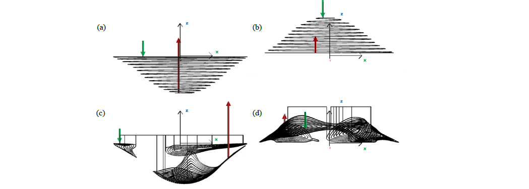
Fig. 1. Toolpath strategies for the second and third multi-stage steps to reprocess the reduced initial geometry. (a) and (b): global spiraling toolpaths for processing the inside and outside (after flipping the part) of the part respectively. (c) and (d): corresponding local feature toolpaths to only process the regions that need extra deformation.
2.2 Global and local toolpath strategies
Because the low order manifold harmonic reconstruction positions equal parts of the target geometry above and below the original surface resulting from the first SPIF operation, the use of conventional spiraling toolpath strategies for the two final steps would mean that the tool only contacts the workpiece half of the time. One solution to increase productivity would be to locally increase the feed rate of the CNC machine in these non-contact zones. Another option is to completely abandon the z-slicing methodology. By intersecting the final surface and the low order reconstruction, the final surface can be split up into two sets of patches that either need to be formed deeper or shallower. These patches can be used as input for the feature toolpath strategy devised by the authors in [11], which use the edge of surfaces to plot a toolpath with a fixed stepover. Separated patches are connected by engage-retract operations, making sure to clear the already formed part to avoid collisions, which could be an issue when forming the flipped part. Locally, the feature toolpath strategy mimics the regular spiraling toolpath strategy used in single step SPIF. The first contours impose only limited deformation to the base, while maximum deformation is achieved in the middle of the patch. The big difference for feature toolpaths is that the base surface is not planar but freeform, as are the toolpath slices. The two toolpath strategies for the reprocessing of the first reduced geometry step are compared in Fig. 1. The green arrows indicate the toolpath starting position, while the red arrows are the final retraction step.
3 Experiment setup
3.1 Materials
Four dual sided SPIF strategies were tested for the creation of a complex freeform workpiece, elaborated in Table 1. The created part geometry was an ellipsoid with principal axes of 80 mm, 64 mm and 64 mm length truncated to obtain a maximum wall angle of 50° at the part edges. The truncated ellipsoid was rotated along the z axis and offset in x-y direction to make the final workpiece asymmetrical, resulting in a larger variation in wall angles and curvatures. The workpiece was finally obtained by embedding the ellipsoid in a sheet of 175x175 mm at a depth of 50mm, ensuring a smooth transition at the part edges. The reduced geometry used as first forming stage for the dual sided strategies was obtained by reconstructing the workpiece geometry using the first 10 manifold harmonics, resulting in a smoothly curved surface. Fig. 2 (a-c) shows a comparison of the reduced and final workpiece geometries. The spiraling and feature based toolpaths used in the different strategies were created using a stepover value of 1mm for the tool of diameter 10mm and 1.5 mm for the 25 mm tool.
The sheet material used for the practical experiments was commercially pure Zn of 1mm thickness, due to its tendencies for overforming at the sheet edges (Fig. 2 (d)), thus benefiting from forming from the opposite side. The parts were formed on a horizontal 3-axis CNC milling machine at a feed rate of 2000 mm/min using non-rotating hemispherical tools of diameters 10 mm and 25 mm. Lubrication was achieved by preapplying a thin layer of Nuto H46 hydraulic oil to the sheet using a brush. The formed parts were digitized between each processing step using a GOM Atos Compact Scan fringe projection scanner. Both front and back side of the clamped part were scanned within the same reference frame in order to calculate the resulting sheet thickness. To analyze the effect of the different strategies on the process accuracy, both the full workpiece and ellipsoid part were compared to the produced parts. Comparison with the full workpiece was done after aligning the measured data to the machining frame of reference, thus showing clearly where over- or underforming occurred. Comparison of the ellipsoid part was done after a best-fit alignment to assess the quality of the functional embedded part.
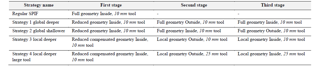
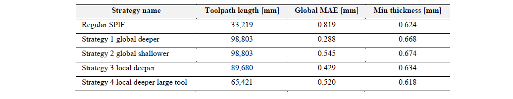
Table 1. Sequential dual sided strategies.
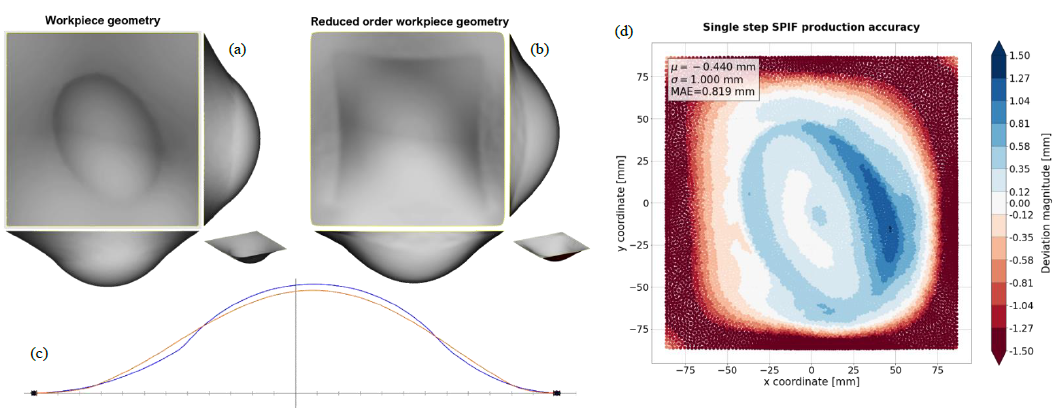
Fig. 2. Test geometry and benchmark accuracy. (a) Embedded ellipsoid workpiece, (b) reduced workpiece geometry and (c) comparison section between reduced (orange) and final (blue) workpiece geometry. (d) Global accuracy plot for regular SPIF production of the workpiece, deviation magnitude is calculated normal to the CAD workpiece
3.2 Practical considerations
The advantages of local toolpath strategies seem very useful in theory. However, practically the execution of these strategies becomes much more complex. The main issue lies with the SPIF process accuracy, which not only means the final part geometry will deviate from the CAD input, but also the intermediate geometry. The generated low order reconstruction will not be recreated perfectly, compromising its specific properties. For materials characterized by large spring back, the produced low order reconstruction will not lie equally above and below the part, instead ending up much shallower, while easily formable materials, such as the used Zn will exhibit more overforming than intended. The accuracy achieved for the low order reconstruction is shown in Fig. 3, along the resulting zones that need extra forming in both direction compared to the intended manifold harmonic behavior. This means that it is unwise to generate the local feature toolpaths purely using the CAD data, since no contact or excessive deformation may thus occur during the subsequent steps.
Fig. 3. Uncompensated reduced workpiece geometry (a) Global accuracy plot of the produced first step, (b) resulting patches for the subsequent stages (red areas needs shallower processing and gray areas need deeper processing) and (c) intended patch geometry for subsequent stages: workpiece is divided equally in deeper and shallower patches.
One solution to this issue is the use of measurement data of the actual produced reduced order geometry to recalculate the intersection patches with the final geometry (Fig. 3 (b)) and use these to construct new local toolpaths. The other solution uses compensation techniques to reduce inaccuracies and make sure the intermediate geometry is as close to the harmonic decomposition as possible so the created toolpaths can be used. Both solutions need accuracy data and thus introduce extra measuring steps in the process chain, making the local toolpath strategies take as much if not more time than the simple global strategies. In this work, the latter solution was used, using measurements of the intermediately created geometries.
Another practical consideration lies with the application of toolpaths from two sides of the workpiece sheet. This means the clamping rig has to be physically flipped around and reaffixed to the machine between subsequent forming steps, which was done in this work along the machining y-axis. After these operations, the CNC machine had to be realigned taking into account the mirrored situation. The distance between the front face and the clamped undeformed sheet was recorded from both sides to be able to reliably align the machining z-axis after the first intermediate shape was formed.
4 Experimental results
4.1 Global workpiece accuracy
Fig. 5 compares the accuracy of the parts produced with the different proposed strategies, aligned to the frame of reference of the production machine. It is immediately obvious that the first strategy (using global toolpaths, with the inside operation last) achieves the highest accuracy with the most uniform distribution. The global Mean Average Error (MAE) is reduced to 35% of the reference single step SPIF method. The two local strategies also manage to lower the MAE, albeit less significantly, to respectively 52% and 63%. The second strategy, using the global toolpath from the outside of the part last, results in a larger MAE caused by almost global underforming behavior. Forming back on the overformed sections from the outside of the part resulted in an overcompensation for the used global toolpath strategy, resulting in underforming of the part. This behavior was corrected in the first strategy by the last inside step, as demonstrated by Fig.4.
The local toolpath strategies are characterized by much larger local accuracy variation. This is especially noticeable for strategy 3, where the smaller tool size caused serious bulging of the processed patches, resulting in the formation of noticeable ridges. This behavior also occurs in regular SPIF, where the bottom of a part with low wall angles shows significant underforming due to the bulging that occurs during processing. In this case, the largest effect was observed for the outside toolpath, where the existing curvature due to the previously formed stage created especially unfavorable conditions. The use of the larger tool of 25mm in strategy 4 mitigated this problem by reducing the bulging of the part during forming. Another reason for the worse accuracy figures, even with strategy 4, lies in the precomputed local nature of the toolpaths. Theoretically, these toolpaths only touch the part where deformation is needed. This is somewhat the case for the second stage, since a compensated input was used to create the first intermediate part. For the third stage, this does not hold up anymore, since the extra forming step also introduces new unknown deformations, causing more regions to need reprocessing in the last stage than expected. The global toolpath strategies do not encounter this problem since in all cases the total surface of the workpiece is traced, forming the part where needed.
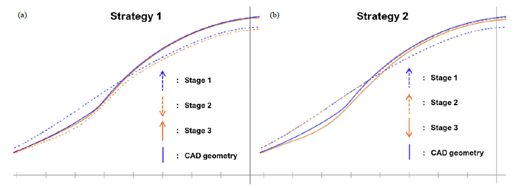
Fig. 4. Section view for the subsequent processing steps for strategies 1 and 2. The arrows indicate the forming direction of the processing steps: (a) strategy1: inside operation last, (b) strategy 2: outside operation last.
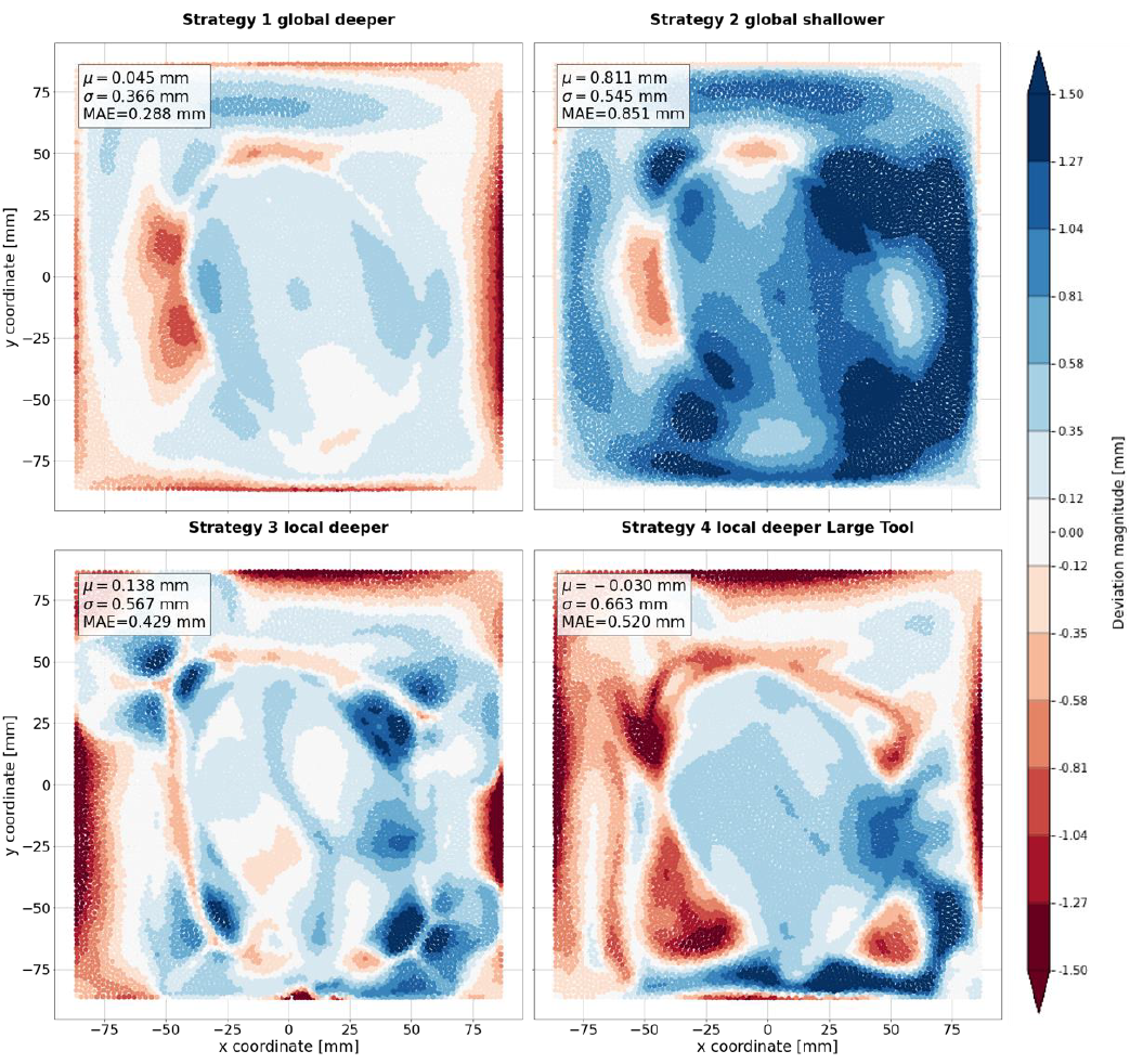 Fig. 5. Global accuracy plots for the parts produced using the tested multi-stage strategies aligned to production frame of reference.
4.2 Local embedded part accuracy
When looking at the accuracy of the truncated ellipsoid part aligned to each individual test using a best-fit, the picture changes somewhat. Differences between the different strategies become smaller, see Fig. 6. The underforming behavior of the second strategy remains limited to 4 local zones, mimicking the underforming of the first stage, while the Mean Squared Error is lower than in the first strategy. The accuracy figures for strategy 3 are the best, at the cost of uniformity of the part surface. The larger tool used in strategy 4 also introduces the largest local error, since deformation is less likely to stay purely local due to the larger contact area and subsequently higher forming forces.
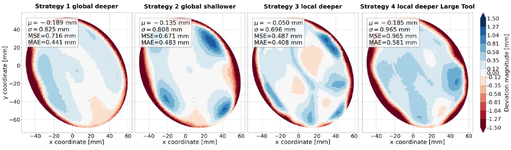
Fig. 6. Local accuracy plots for the parts produced using the tested multi-stage strategies best-fit aligned to the ellipsoid part.
4.3 Thickness distribution
Because the wall angles of the reduced shape are very close to those of the final CAD shape (a maximum of 47° vs. 51°), this multi-stage approach does not significantly increase the process limits. While the sheet thickness distribution is more uniform in the first two strategies, the minimum part thickness only improves by ~0.05 mm as shown in Fig. 7. The local toolpaths cause a similar minimum thickness to be reached as regular SPIF, albeit in different locations. However, the local ridges that get formed due to the feature approach in strategy 3 result in much higher local sheet thickness.
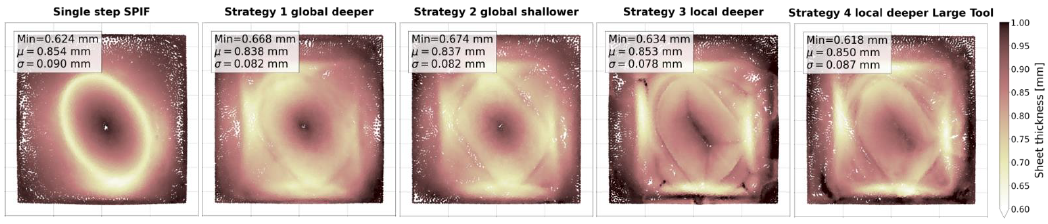
Fig. 7. Resulting sheet thickness plots for the parts produced using regular SPIF and the tested multi-stage strategies.
4.4 Part surface quality
The spiraling and feature toolpaths used were created with stepover values that were relatively low, resulting in a small scallop height. This resulted in workpiece surfaces with a satisfactory smooth finish. As mentioned before, however, the local toolpath strategies resulted in bulging of the part during forming, creating noticeable ridges at the end of the toolpath sections. Although the effect of these ridges on part accuracy remain relatively limited, they are immediately noticeable upon observation of the part by eye, and were even reflected clearly in the digitized data, as can be seen in Fig. 7 (c-d), making these strategies ill-suited for the production of decorative parts.
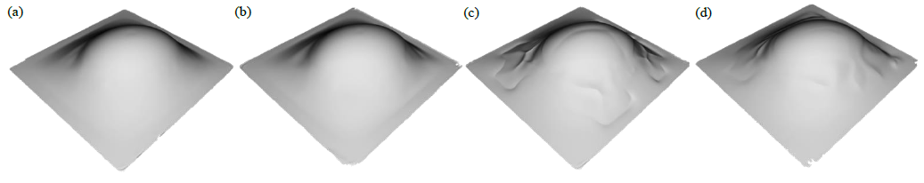
Fig. 7. Shaded rendering of the measured parts, clearly demonstrating geometric imperfections. (a) Strategy 1 global deeper, (b) strategy 2 global shallower, (c) strategy 3 local deeper and (d) strategy 4 local deeper large tool.
Table 2. Sequential dual sided strategies.
5 Discussion
Although coupling the capabilities of the manifold harmonic decomposition with the use of local 3D feature toolpaths seems like a good idea in theory, practice shows a number of issues that make the combination of both techniques less than ideal. Using manifold harmonics, it is easy to generate a derived low order reconstruction using a freeform workpiece geometry. By sequentially forming this reduced shape into its final shape from two sides, it is possible to achieve better part accuracy. The use of local toolpaths is however made very tricky due to the accuracy behavior of the SPIF process, since a formed part will always deviate from its CAD input. The need for measurements during the intermediate stages, coupled with the specific issues with using feature toolpaths to impose only a minimal amount of deformation, make this approach much less appealing than the global toolpath approach.
As summarized in Table 2, the global approach (Strategy 1) can significantly increase the accuracy of the studied workpiece at the cost of extra processing time, needing a cumulative toolpath that is 3 times longer and an extra operation to flip the part. A smart selection of a larger tool size for the initial step could alleviate the processing time requirements. By transitioning from sequential SPIF to DSIF, these last two forming stages can be combined, regaining the time advantage and possibly an extra increase in accuracy, so this is a track that will be investigated in follow up research.
Acknowledgements
This study was facilitated by the KU Leuven BioMeTIOMatic C2 grant and the support of Flanders Make.
