1 Introduction
Hole-flanging is a very common forming operation that aims to strength the hole edge, improve its appearance or provide additional support when joining sheet parts. The conventional press working (PW) method produces a hole-flanged part by clamping a blank sheet with a pre-cut circular hole and performing a single punch stroke. Recently, the single-point incremental forming (SPIF) process has emerged as a new flexible and cost effective tooling method compared to conventional processes. In hole-flanging by SPIF, the blank sheet is deformed in a CNC machine by a forming tool that follows a pre-established trajectory to progressively produce the flange.
The pioneering research on hole-flanging by SPIF is attributed to Cui and Gao [1]. They analysed different multi-stage SPIF strategies and compared the limit forming ratio (LFR) obtained in each case. The LFR is the traditional parameter used to measure formability in hole-flanging processes. It was defined as the maximum hole expansion ratio (HER) attained by the material without failure [2-3]:

where d0 and df are the initial diameter of the pre-cut hole and final inner diameter of the flanged part, respectively. Although the performance of the LFR is well established in conventional PW processes, recent researches point out that is not an appropriate parameter for measuring the formability in hole-flanging by SPIF [4].
Only a few authors included the use of the Forming Limit Diagram (FLD) when studying the flangeability in hole-flanging by SPIF. Among them, Centeno et al. [5] studied the flange deformation and failure of aluminium 1050 sheets, or Martins and coworkers [6-9] who compared flangeability in different materials by PW and SPIF using both the LFR parameter and the FLD. These works performed hole-flanging by using a multi-stage strategy commonly used in SPIF processes. However, a less timeconsuming single-stage SPIF (SPIF1) strategy can also be used to obtain functional flanges, as pointed out by Borrego et al. [4].
In general, both PW and SPIF technologies to produce hole-flanged parts have been studied separately using different approaches and, therefore, most studies cannot be easily compared. In this sense, the authors carried out series of experimental tests of holeflanging by the SPIF1 strategy [4] and conventional PW [10] on aluminium 7075-O sheets. The experimental results were used to analyse flangeability and compare both forming processes in terms of the traditional LFR and FLD [11]. Since the LFR was not an appropriate parameter to measure flangeability in SPIF, two complementary parameters to the LFR were proposed. Furthermore, the FLC for necking and FFL for fracture curves traditionally evaluated in the FLD yield some erroneous prediction of necking in PW and fracture in SPIF.
This work presents a comparison and analysis of flangeability of hole-flanging by SPIF1 and PW in AA7075-O sheets. The main contribution of this work relative to earlier works [4,10,11] is a special focus on the limitations of conventional LFR and FLD failure prediction tools. Complementary parameters to the LFR to evaluate flangeability are discussed, along with the influence of bending and the stress triaxiality induced by the forming tool in the evolution of the principal strains.
2 Experimental Procedure
A series of hole-flanging experimental tests by PW and SPIF1 using aluminum sheets of AA7075-O of 1.6 mm thickness was performed in previous works [4,10]. A different set up was built for each forming process as represented in Fig. 1. Briefly, Fig. 1(a) depicts the hole-flanging process by PW carried out in a Erichsen 142-20 machine. The blank with the initial pre-cut hole of diameter d0 is clamped between die and blank holder while the action of an emerging punch conforms the part in a single press stroke. The SPIF1 process is depicted in Fig. 1(b). The blank with the initial pre-cut hole is clamped between a blank holder and a backing plate in an EMCO VMC-200 3-axis milling CNC machine. A hemispherical forming tool follows a previously established helical trajectory. The final inner diameter of all hole-flanged parts was df = 95.8 mm.
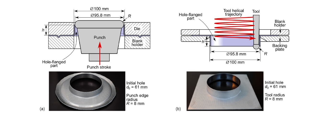
Fig. 1. Schema of hole-flanging processes and successful parts manufactured by (a) PW and (b) SPIF1.
The experimental test plan was carried out on sheets with initial pre-cut holes between 41 and 83 mm in diameter, punches for PW with R = 6, 8, 10 and 47.9 mm edge radii and forming tools for SPIF1 with R = 6, 8 and 10 mm radii [4,10]. The tools in both processes were chosen with same R values to analyse the bending effect on formability. Successfully manufactured parts by PW and SPIF1 with same parameters d0 = 61 mm and R = 8 mm are shown in Fig. 1.
Specimens were previously electro etched with a dot grid of 1 mm in diameter and spaced by 2 mm. The optical 3D forming analysis system ARGUS® was used to automatically compute the principal strains on the sheet surface. Since this analysis system is not able to compute strains near the hole edge due to the lack of data for interpolation, the strains at the hole edge were calculated from direct measurement of the final and initial perimeter of the hole and the final and initial sheet thickness, and assuming material volume constancy.
3 Results
The different modes of failure observed in failed specimens are shown in Fig. 2. In case of PW the failure was by localised necking followed by ductile fracture just at the edge (Fig. 2a) or close to the edge (Fig. 2b). As can be observed, narrow bands always developed in the radial direction and firstly in rolling direction. On the other hand, the mode of failure in SPIF1 was ductile fracture without previous necking located in the middle of the wall in all cases (Fig. 2c). The specimens were cut across the crack at the fracture initiation site to confirm the failure mechanism under a microscope.
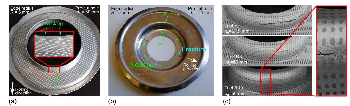
Fig. 2. Pictures of failed tests: necking (a) at the edge and (b) far from the edge in PW, and (c) fracture in the flange wall in SPIF1.
The forming limits can be analysed using the traditional FLD. However, the representative loop in the FLD that describes the strain distribution of specimens tested by SPIF1 (which is a consequence of the inversion of the major and minor strain that occurs along the flange, see [11]) makes the comparison with the simpler shape obtained by PW difficult. Therefore, in this work the analysis in the major-minor strain space (ε1-ε2) of the traditional FLD was changed by the meridional-circumferential strains (εm-εc) along the flange.
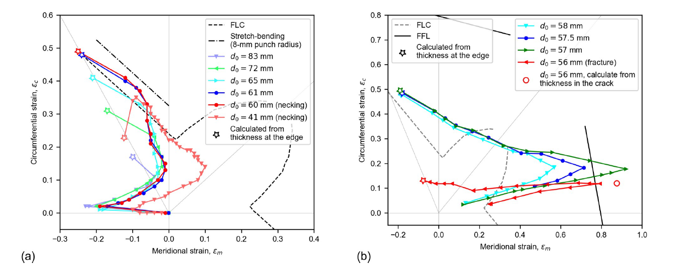
Fig. 3. In-plane strain distribution along the flange for specimens formed by (a) PW with R = 8 mm and (b) SPIF1 with R = 10 mm.
Fig. 3 presents the strain distributions along the flange of the experimental results for PW with the punch of 8 mm edge radius and SPIF1 with the 10 mm tool radius. The results include successful and failed specimens. The results trend was similar with the rest of punches and tools. The open stars in Fig. 3 represent strains calculated at the flange edge, as explained above. As can be seen, all open stars in PW and SPIF1 followed the strain path β ≈ –0.5 corresponding to the uniaxial tension conditions characteristic of a hole edge expansion [2-3].
The most remarkable fact noted in experimental results by PW (see Fig. 3(a)) is that the strain distributions for the successful specimens with pre-cut hole of 65 and 61 mm diameters are above the FLC. This phenomenon of exceeding the FLC without failure at some point along the flange is due to the bending effect of the strain gradient through the sheet thickness, as was explained in [10]. However, for the failed specimen using the punch with 60 mm diameter (see Fig 2(a)), the FLC was able to predict the onset of necking just at the hole edge tip, as can be observed in Fig. 3(a). This is because the bending effect along the flange dissipates at the edge tip. Thus, it can be concluded that the conventional FLC is not a suitable tool for analysing the material formability along the flange, except at the flange tip.
Regarding the bending effect, it is well known that bending induced by forming tools increases strains on the sheet surface before the onset of necking [12]. To quantify the effect of bending, the authors developed a series of stretch-bending tests using cylindrical punches of 10 and 6 mm radii [10]. The measured forming limit strains from these tests were extrapolated to estimate the forming limit curve for stretch-bending with a 8 mm punch radius represented in Fig. 3(a). As can be seen, this FLC with bending indicates that necking was not expected to occur in the flange wall.
The failed specimen by PW using a 41 mm pre-cut hole diameter represents a case where the traditional FLC does predict necking, as seen in Fig. 3(a). Note in Fig. 2(b) that in this specimen the narrow bands initiated far from the hole edge in a material region subjected to stretching without bending.
On the other hand, the strain distribution of specimens formed by SPIF1 exhibited an enhanced formability in terms of strain in meridional direction compared to PW, as can be seen in Fig. 3. Thus, the successful flanged parts that were obtained using blanks with d0 = 58 and 57.5 mm presented strains in meridional direction in the middle of the wall clearly above the FLC (which is not applicable to SPIF) and very close to the FFL. Instead, the FFL was clearly overcome for the fractured specimen with d0 = 56 mm (see Fig. 2(c)(bottom)). This apparent enhancement of formability could be due to the minor levels of stress triaxiality in SPIF compared to conventional forming processes [13]. A significant reduction in thickness was observed in the wall middle of all specimens.
Regarding the LFR, as expected, it remained constant with R and was equal to 1.57 in PW tests. This indicates that the punch profile did not significantly influence successful flange formation [2-3]. Indeed, the LFR in PW, that is related to the hole edge expansion, is supposed to be a material constant that can be obtained from the limit major strain at necking under uniaxial tension (ε1,UTneck) as

However, in hole-flanging by SPIF1, the LFR increases as R increases with values that range from 1.46 to 1.66. The LFR values for PW and SPIF1 are represented on the x-axis in both diagrams of Fig. 4 as the maximum HER obtained in successful specimens. As can be seen, the LFR is not an appropriate parameter to compare flangeability of PW and SPIF1 processes. Inplane strain distribution along the meridional direction for specimens formed by SPIF1 with a 10-mm radius tool. As seen in Fig. 3 and Fig. 4 two different forming process exhibited almost the same LFR as far as they achieved successful tests with almost the same circumferential strains at the edges, but with very different strain distributions in the FLD.
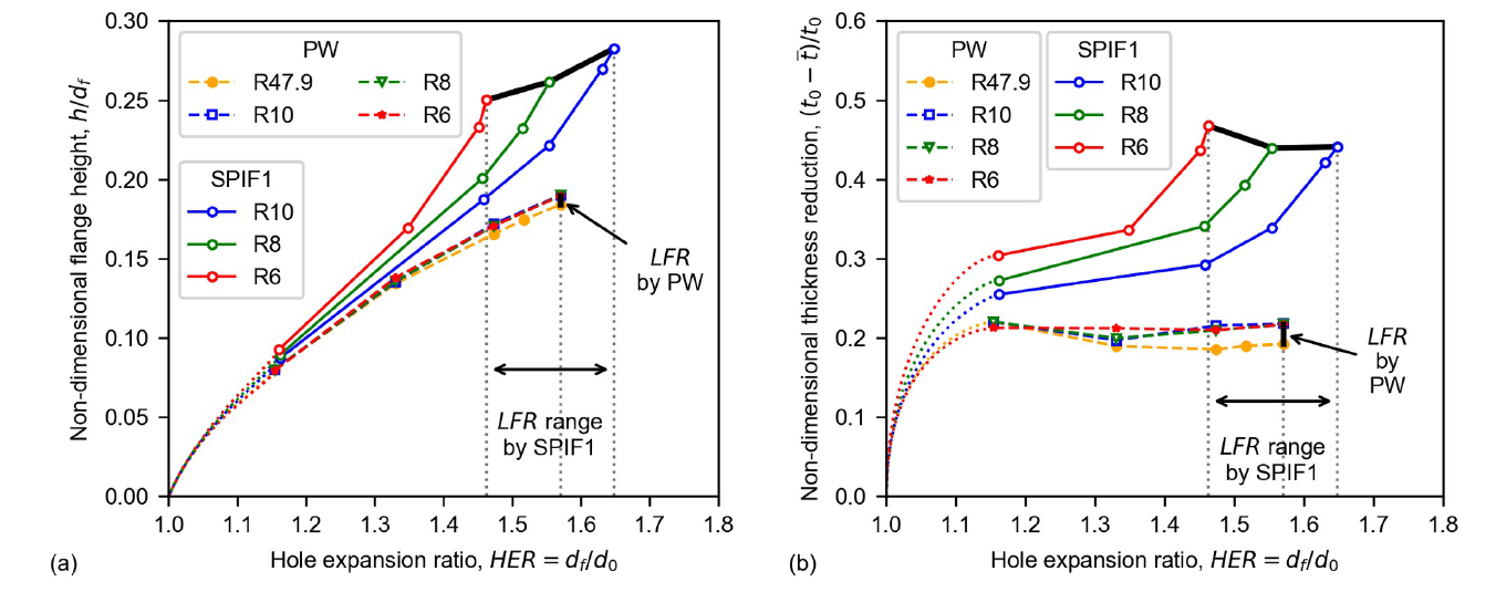
Fig. 4. Non-dimensional (a) flange height and (b) thickness reduction of successful hole-flanged parts of different HER manufactured by PW and SPIF1.
The two proposed parameters to measure flangeability have been represented on the y-axis of both diagrams in Fig. 4: (a) the non-dimensional flange height (h/df , where h is the flange height measured in successful specimens) and (b) the nondimensional thickness reduction ((t0−t̅)/t0, where t̅ is the average flange thickness calculated from volume constancy). The experimental results of all successful specimens by PW and SPIF1 are plotted in both diagrams. The coloured lines join the results that were obtained with the same punch in PW (dashed lines) or the same tool in SPIF1 (continuous lines). Note that the nearly overlapping dashed lines show the expected insensitivity of the PW process to R. On the other hand, it can be seen for SPIF1 that, for a given HER, the flange height and thickness reduction increase as R decreases, in accordance with accepted SPIF trends. This means that tools with smaller radii can further stretch the material in the meridional direction of the flange.
The improvement of formability in SPIF1 compared to PW is clearly seen in Fig. 4 using the proposed parameters instead of the LFR. This quantifies as a enhancement of flange height up to 47% and a gain of average thickness reduction up to 113%.
4 Conclusions
The flangeability in hole-flanging by PW and SPIF1 has been compared in terms of strains in the meridional direction, the LFR and two additional flangeability parameters recently proposed. The main conclusions can be summarized as follows:
1 The analysis in the strain space satisfactorily describes the failure mechanisms in both processes. The enhancement of formability of SPIF1 compared to PW is better understood by representing the principal directions (circumferential vs. meridional) of the flange instead of the traditional FLD.
2 However, the traditional strain-based FLC for necking and FFL for fracture were not the most adequate tools to analyse the influence on formability of phenomena such as the bending effect in PW and the stress triaxiality in SPIF. The evaluation of these phenomena requires other alternatives such as the forming limit stress diagram (FLSC) or the equivalent plastic strain based forming limit curve (epFLC) [13].
3 Since the LFR is a measure of the maximum circumferential strain achieved at the hole edge, it successfully describes flangeability in PW processes. However, it does not capture the physics of failure in SPIF1 that occurs in the middle of the flange. Therefore, the LFR may yield confused conclusions when used to measure the flangeability in SPIF processes.
4 The two parameters proposed as an alternative to the LFR, the non-dimensional flange height (h/df ) and thickness reduction ((t0−t̅)/t0), are suitable for analyzing the formability in hole-flanging by PW and SPIF1. In terms of these parameters, SPIF1 exhibits a significant improvement in flangeability compared to the PW process.
Acknowledgements
Grant PGC2018-095508-B-I00, financed by FEDER (ERDF, European Regional Development Funds)/Ministry of Science and Innovation – State Research Agency of Spain.
