1 Introduction
In 2010, CEA revived studies on Fast Sodium Reactors (SFRs). The main goal was to build a demonstrator, first called ASTRID. In 2018, ASTRID’s capacity was reduced from the original, commercial 600 MWe to a 150 MWe research model (150 MWe SFR). In this framework, many studies started to ensure that the industrial base was able to produce the structural elements of the reactor’s core, including the hexagonal wrapper steel tube containing the nuclear fuel claddings [1]. The hexagonal geometry provides maximal compactness in the reactor’s core, so that its maximal capacity can be reached.
The tube dimensions have to be precisely known and controlled. They are shown Fig. 1a. The tubes are made of 9%Cr – 1% Mo tempered martensitic steel providing high stability of microstructure and satisfactory mechanical properties under irradiation. Grade EM10 has been selected as reference material but, due to availability considerations, the normalized Grade P91 steel is used for this study. In the past, the fabrication route involved hot extrusion of pierced cylindrical billets in a round-shaped die, followed by several cold drawing passes to obtain both hexagonal shape and wall thickness reduction [2]. The feedback pointed out geometrical and surface defects. Therefore, CEA is considering direct hot extrusion in a hexagonal die to ensure more uniform strain in the cold drawing passes.
A first set of hot extrusion experiments at 1250 °C was carried out by CEA’s subcontractor, resulting in two hexagonal semi-products shown Fig. 1b. The dimensions of the semi-products, about 12 mm extruded tube wall thickness, are relatively far from the 3.6 mm thickness needed, leaving a large reduction for cold drawing. The measured pressure curve (Fig. 2) shows a force Fₚₑₐₖ at 2200 tons, around 25% more than the steady extrusion pressure (Fₛₛ) and very close to the capacity of the press. This is what restricts a decrease of semi-product thickness.
A simulation of the process using finite-element computation in ForgeNxt® was designed in order to understand the origin of the pressure peak. The real initial billet temperature at the beginning of extrusion has been modelled by chaining furnace-to-press transfer, waiting time with the preform in contact with the die, and initial compression filling the gap between the billet, the container and the needle. This proved quite important for the problem at stake. Material and interface data were selected based on steel extrusion literature. Friction coefficient and heat transfer coefficient (HTC) were used as varying parameters and were eventually found non-uniform if the peak amplitude is to be recovered.

Fig. 1. Dimensions and shape of the hexagonal wrapper steel tubes (a) Required dimensions for the final product (150 MWe SFR design), and (b) shape of the first two extruded tubes after cooling.

Fig. 2. Pressure (blue), nominal (green) and true speed (red) measured in the first set of hexagonal extrusion.
2 Model construction
First, a valid 2D-axisymetric model was built to identify the set of key numerical parameters required to be compatible with the experimental results and was used for sensitivity analysis. Next, a 3D-hexagonal model with the same thermomechanical parameters confirmed the trends observed in 2D.
The shape and condition of the tools and of the lubrication system, beyond the dimensions imposed by those of the billet and extruded tube, were considered confidential by the subcontractor. Thus, the design was based on the best practice of the field, also derived from the literature. These choices are described in details in this section.
2.1 Lubrication in hot extrusion
The hot extrusion of steel was enabled with the Séjournet process [3,4], using glass, a suitable lubricant withstanding high temperature in the range 1000 – 1300 °C. The heated billet leaves the furnace and is rolled over a thin glass-powder covered table, so that the external surface of the billet is covered with a ~5 µm glass layer. Then, a glass pad between 6 and 20 mm thick, made of mixture of glass fibers, glass powder and binders, is put in contact with the die inside the container [5,6].
The lubrication is provided by the continuous erosion of the glass pad during the extrusion, forming a thin, molten glass film of about 20 µm along the metal. The second purpose of the glass pad is to avoid the formation of a dead metal zone in the container/die angle, facilitating the metal flow [5]. The erosion phenomenon has been studied in details by D. Damodaran and R. Shivpuri [7]. The heated billet is put in contact with the glass pad when the extrusion begins. The superficial layer of the pad is also heated up through thermal conduction, resulting in a viscosity drop of this layer. The pressurized metal starts to flow through the die and drags the viscous glass layer with it through a hydrodynamic mechanism, allowing the thick film lubrication of the internal surface of the die and the die land. The viscosity and thermal diffusivity of the glass as well as the billet and die temperatures and HTC are critical parameters for this lubrication to work properly.
Lubrication and friction during hot extrusion were investigated by B. Gaudout [8]. In the absence of a complex modelling of the two-material flow, viscous glass and viscoplastic metal, friction in lubricated hot extrusion is best described with a Tresca- restricted Coulomb’s law:

where p is the pressure, σ0 is the flow stress of the steel, 𝜇 and m̄ are the Coulomb and Tresca coefficients, respectively. Glass lubrication allows very low friction in the steady state, typical values are µ ≤ 0.01 [9]. The Tresca coefficient restricts the excessive increase of the friction stress with pressure, considering the finite shear stress of the superficial metal and/or interfacial medium.
2.2 Tools and billet thermomechanical properties
In the model, the die is supposed flat, with a 10 mm entrance corner radius and a bearing length of 6 mm, industrial standards for the extrusion of steel [5]. The tool steel is characterized by its HTC value: 9000 𝑊.𝑚².𝐾⁻¹ [4,5]. The needle is supposed perfectly cylindrical, solid and isothermal with the same temperature as the die (400 °C). The glass pad is not explicitly modelled. It is replaced by its thermal insulator effect, a HTC value estimated at ~120 𝑊.𝑚².𝐾⁻¹ from the thermal conductivity of borosilicate glass at ambient temperature and a pad thickness of 10 mm. The thin glass layer on the lateral surfaces of the billet is neglected due to its thinness providing insignificant thermal resistance, acting just by the local friction coefficient.
The billet is made of P91 grade steel, homogeneously heated to 1250 °C then transferred in about 50 s to the extrusion press. This transfer at workshop room temperature in air adds a thermal gradient inside the billet. E. Piozin determined the phase diagram of P91 steel with 0.1% of C [10]. MX (Nb,V)(N,C) precipitates are expected until 1150 °C, and 𝛿-ferrite appears around 1260 °C. Thus, the temperature of the metal should be restricted to this interval during extrusion. The behavior of the P91 steel is described with the constitutive equation of Hansel and Spittel:

where 𝜎 is the stress, 𝜖 is the strain, 𝜖̇ the strain rate, T the temperature, and the coefficients are determined by fitting experimental data from the literature. D. Samantaray and al. carried out isothermal compression tests at different temperature, ranging from 850 to 1150 °C, and different strain rate from 0.001 s⁻¹ to 100 s⁻¹ [11,12]. To match the extrusion conditions, their results were extrapolated to a temperature of 1250 °C, which is a strong assumption considering carbide dissolution, and a strain rate of 25 s⁻¹ . Thermal data for P91 steel was taken as already implemented in the software: conductivity 𝑘 = 35.5 𝑊.𝑚-1.𝐾-1, emissivity 𝐸 = 0.88, specific heat 𝑐 = 778 𝐽.𝑘𝑔⁻¹.𝐾⁻¹ .
2.3 2D numerical model
A global view of the 2D-axisymmetric model is shown Fig. 3a. To simplify, the system {die} groups the die and the container, while the system {needle} groups the needle and the ram. They are both undeformable and isothermal at 400 °C. To save computing time, the billet length is shortened from 850mm to 150mm, sufficient to reach steady state extrusion. Dimensions are partly based on measurements on the first two extruded tubes, from which an extrusion ratio of 5.7 was identified. However, in 2D the circumferentially variable reduction of the hexagonal shape cannot be represented. We decided to keep the internal diameter (needle) and the external diameter (die) values in accordance with the experimental conditions, thus increasing the extrusion ratio to 6.5. The {die} is static, the {needle} is moving at ram speed 270 mm/s.
The transfer between the furnace and the extrusion press is implemented as a cooling step ttransfer = 50 s in air before the extrusion step. The waiting step right before the extrusion is modelled with a variable waiting time twₐᵢₜ inside the container. The glass pad is not geometrically modelled but represented by its action: first, as a thermal insulator, and second as avoiding the formation of a dead metal zone in the container-die angle. Hence, the HTC of the tool steel is locally lowered where the pad should be, and a radius of curvature of 10 mm is added at the container/die angle. This simplified setting avoids complicated bi-material computations. A close-up view of the 2D model displaying the different HTCs is shown Fig. 3b.
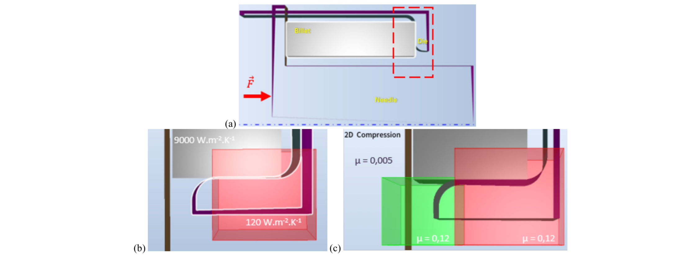
Fig. 3. Geometry and settings of the 2D model. (a) Global view of the {die}, {needle}, billet, (b) close-up view displaying HTCs of tools and of glass pad (red box), and (c) close-up view displaying the friction coefficient µ during the “Compression” step corresponding to transitory lubrication regime.
Table 1. List of the presented 2D-cases with their parameters

A number of surface conditions have been investigated; the most interesting ones are summarized as cases 0 to 3 in Table 1. The friction coefficients are implemented as a surface property of the tool. In a first simulation (case 0), µ = 0.005 is considered uniform and constant during the whole process. In the other three simulations, µ is space- and time-dependent to study the impact of a bad transient lubrication on the extrusion force curve. To do so, the extrusion step is divided into two consecutive steps. “Compression” starts when the ram hits the billet and ends when the metal starts to cross the exit of the die. “Extrusion”, identical in the three simulations, consists in the steady state, where the lubrication regime is supposed to be established, with a uniform and constant µ = 0.005. In the “Compression” step, µ is locally increased in the glass pad lubricated areas (Fig. 3c). Two values are chosen: µ = 0.12 (case 2) corresponds to extrusion without lubrication [3], whereas µ = 0.08 (case 1) represents perturbed glass lubrication. In the last simulation (case 3), the billet is kept a longer time in contact with the glass pad before extrusion, to evaluate the impact of a potential coupled effect of excessive cooling of the head of the billet with a bad lubrication regime.
2.4 3D geometry
Finally, a 3D geometrical model (Fig. 4) has been set up to confirm the tendency observed in 2D. The main parameters are exactly as in 2D except for the tool geometries. All the known dimensions are respected, and unknown die dimensions are based on the literature review as above. Due to high computation time, only two cases from table 1 above were checked with 3D, case 0 as the reference and case 2 as it gave the force peak closest to the experiment.
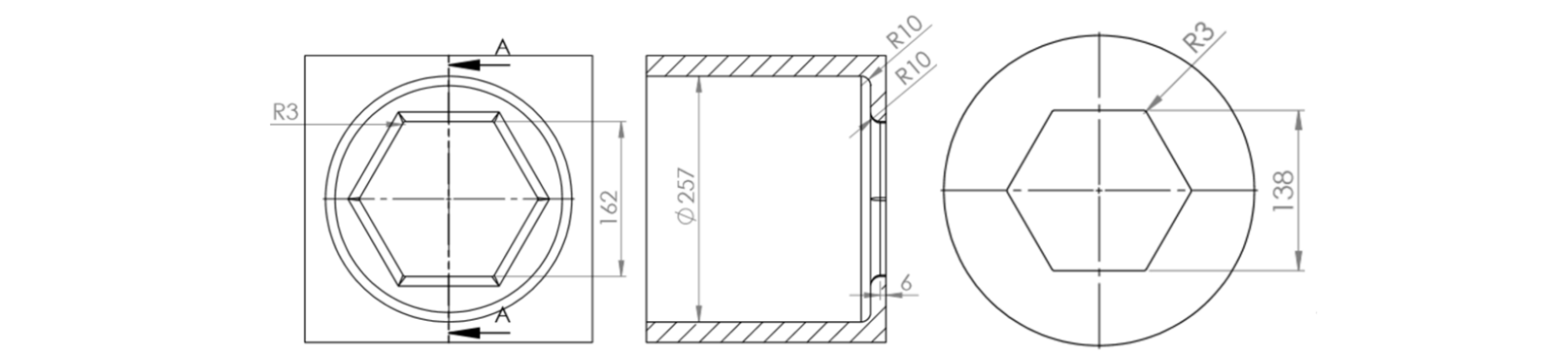
Fig. 4. From left to right: front view and cross-section view of the hexagonal {die}, front view of the hexagonal {needle}.
3 Results
3.1 2D-axisymmetric force curves
To obtain viable results, the extrusion model was first adjusted in 2D, thanks to low computation time. The force curves of cases 0 to 3 are shown Fig. 5. The general trends are in accordance with experimental curves [3-5]. First, the billet is compressed inside the container until it fills the container-needle gap, then a force peak Fpeak is observed at the beginning of the extrusion, and finally the measured force drops to a relatively stable steady-state value Fss. The force increases at the end of the extrusion, due to the shortened length of the billet leading to an excessive cooling.
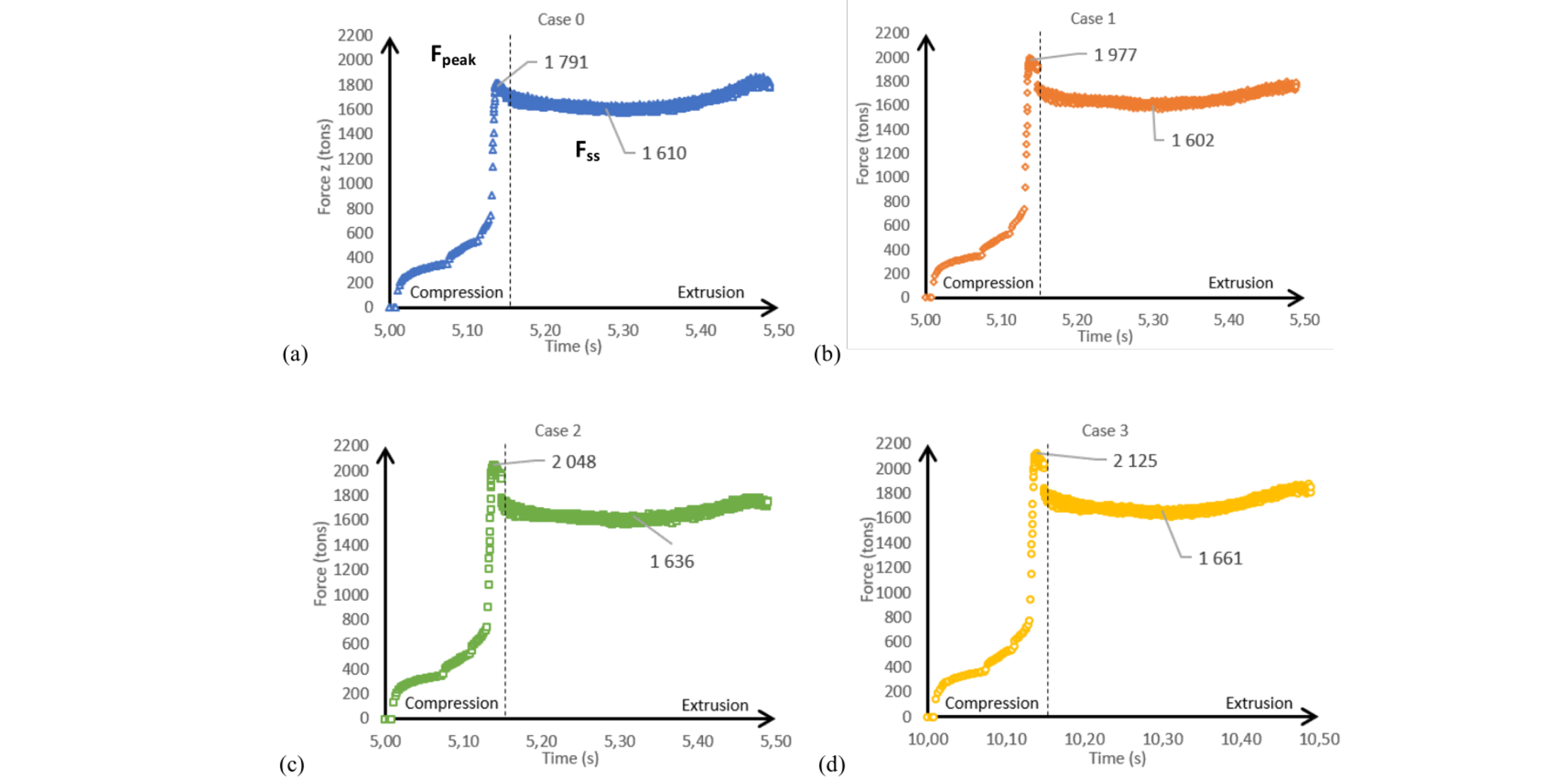
Fig. 5. 2D simulations results: force curves as a function of time for cases 0, 1, 2 and 3. (a) µcompression = 0.005, (b) µcompression = 0.08, (c) µcompression = 0.12, and (d) µcompression = 0.12 and twait = 10 s.
The influence of transfer and waiting times on force curves is shown Fig. 5a. With a uniformly small friction coefficient, the thermal gradient inside the billet, the head being ~50 °C colder, leads to a small Fpeak around 11% greater than Fss. Fig. 5b and 5c show the influence of a transient lubrication regime at the beginning of the extrusion. For µcompression = 0.08, the ratio Fpeak/ Fss ~ 1.23. For µcompression = 0.12, Fpeak/Fss ~ 1.25, a ratio close to Fig. 2. In case 3, the head of the billet is much colder than its inner part (-100 °C). This results in a significant further increase of Fpeak and a slight increase of Fss, the difference reaches 28%. From these results, it is clear that the force peak is partly created by the thermal gradient inside the billet, but cannot be completely explained without a time-dependent friction coefficient.
3.2 3D-hexagonal force curves
The force curves presented Fig. 6 confirm 2D simulations in terms of pressure peak. On the other hand, the difference in the extrusion ratio between cylindrical (6.5) and hexagonal (5.7) extrusion causes a drop in force. Its percentage is well estimated from a simple extrusion force formula where friction is neglected [3,4]:

where F is the extrusion force, R the container radius, l int the side length of the hexagon (needle), σY the yield stress, ρ a correction factor for redundant work and δ the extrusion ratio.
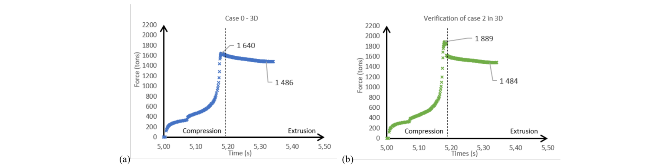
Fig. 6. 3D simulations results: force curves as a function of time for cases 0, and 2. (a) µcompression = 0.005, (b) µcompression = 0.12.
Just as in 2D, the thermal gradient inside the billet leads to a small peak, around 10% greater than Fss. When µcompression is increased to 0.12, the difference reaches 27% of Fss. Thus, a bad transient lubrication regime leads to an increase of Fpeak of the same order as in 2D, confirming also that the axisymmetric approach is a good tool for phenomenon understanding in this case. When extrusion starts, the lubrication regime is affected by the temperature of the top layer of the glass pad. The latter can be lower than expected due to an excessively cooled down head of the billet as well as a low tool temperature. As a matter of fact, it has been noticed experimentally that Fpeak/Fss decreases slightly as successive tubes are being formed, confirming the importance of the thermal regime of the container/die/pad system.
4 Conclusion
With data mainly coming from the literature, a numerical model of the hot extrusion process was built and computed using the finite-element method. Cylindrical extrusion was first computed to adjust the key parameters in 2D. Hexagonal extrusion was then computed to confirm the results with the real shape.
The hypothesis of a degraded transient lubrication regime in the beginning of the process seems to explain the excessive pressure peak measured during experimental tests. Die cooling and the transfer time between the furnace and the press could be the main coupled causes of a colder billet head that may, in turn, enhance the friction drift by slowing down glass melting. These parameters affect the temperature of the billet head and glass pad, and consequently glass viscosity. In the present case, the thermal gradient inside the billet is responsible for a 10 % peak, higher transient friction adds 15 to 20 % more.
In the present study, the glass pad was not modelled explicitly, but rather replaced by its two main purposes: be a thermal insulant between the die and the billet, and prevent the formation of a dead metal zone on the container/die angle. Its impact on friction had to be fitted. To go further in the understanding and prediction of lubrication effect on hot extrusion force with various tube shapes, a bi-material model should be created. This will be a challenge due to the very different behaviors of metal and glass, leading to very large strain and mesh distortion, requiring powerful mesh adaptation.
Acknowledgments
The authors gratefully thank EDF (Electricité de France) for financial support.
