1 Introduction
The thermal control of the hot extrusion process is a mandatory activity in order to obtain sound products, while preserving the production rate in relation to the high temperatures developed for friction and deformation [1,2]. Indeed, an excessive increase of temperatures nearby the bearing zones, where the profile gets its final shape, can lead to surface defects and then to a final product waste. In addition, steep thermal gradients can reduce the service life of tools due to excessive wear and thermal fatigue [3-4]. In this context, the liquid nitrogen cooling of the extrusion die is a widely adopted industrial practice to remove heat in the areas where the highest temperatures are reached as well as to reduce the exit profile temperature [5-6].
The cooling channels are milled in the third plate (backer) surface in contact with the die, while the exit channels are drilled in the die to convey the nitrogen flow to the exit profile surface. Liquid nitrogen removes heat from the tooling set while gaseous nitrogen, at the exit of the channel, covers the profile of an inert atmosphere reducing the oxidation and, to a small extent, the profile temperature.
Even if capabilities of liquid nitrogen systems to significantly increase the production rate in extrusion have been established [7], channel design is still often based on die-makers experience and the performances strongly dependent on many geometrical, thermal and fluid dynamics parameters [8].
If the experimental assessment of the cooling performances is a time and cost-consuming activity, numerical models allow evaluating different design solutions in a relatively short time without the costs of manufacturing. The finite element modelling (FEM) of hot aluminum extrusion process is a yet well-consolidated practice to predict the main output parameters in terms of thermal gradient, extrusion load and potential profile and tool defects [9-12]; however, only few works deal with the modelling of cooling. In this context, aim of this work is further assessing the potentiality of a 3D numerical model of the extrusion process integrated with a 1D model of the cooling channel, proposed by the authors in a previous work [13], against a more complex industrial case study. The capabilities of the numerical re-design of the channel are also shown with the aim to obtain during the die design stage an optimal cooling solution in terms of balanced thermal field and nitrogen consuming.
2 Experimental Campaign
The industrial profile showed in Fig. 1 was selected for the experimental campaign. The mandrel, the die and the backer compose the tooling set (Fig. 2). The planar cooling channel with a rectangular cross section of 6,1x2 mm (wide x depth) surrounds the profile exit, while eleven transferring holes with 5 mm of diameter convey the nitrogen from the cooling channel to the profile surface. The channel is made in the backer on the face in contact with the die and positioned at 37 mm far from the bearing zones, while the transferring holes are drilled in the die supporting a gas nitrogen cooling of the profile surface and protection against oxidation.
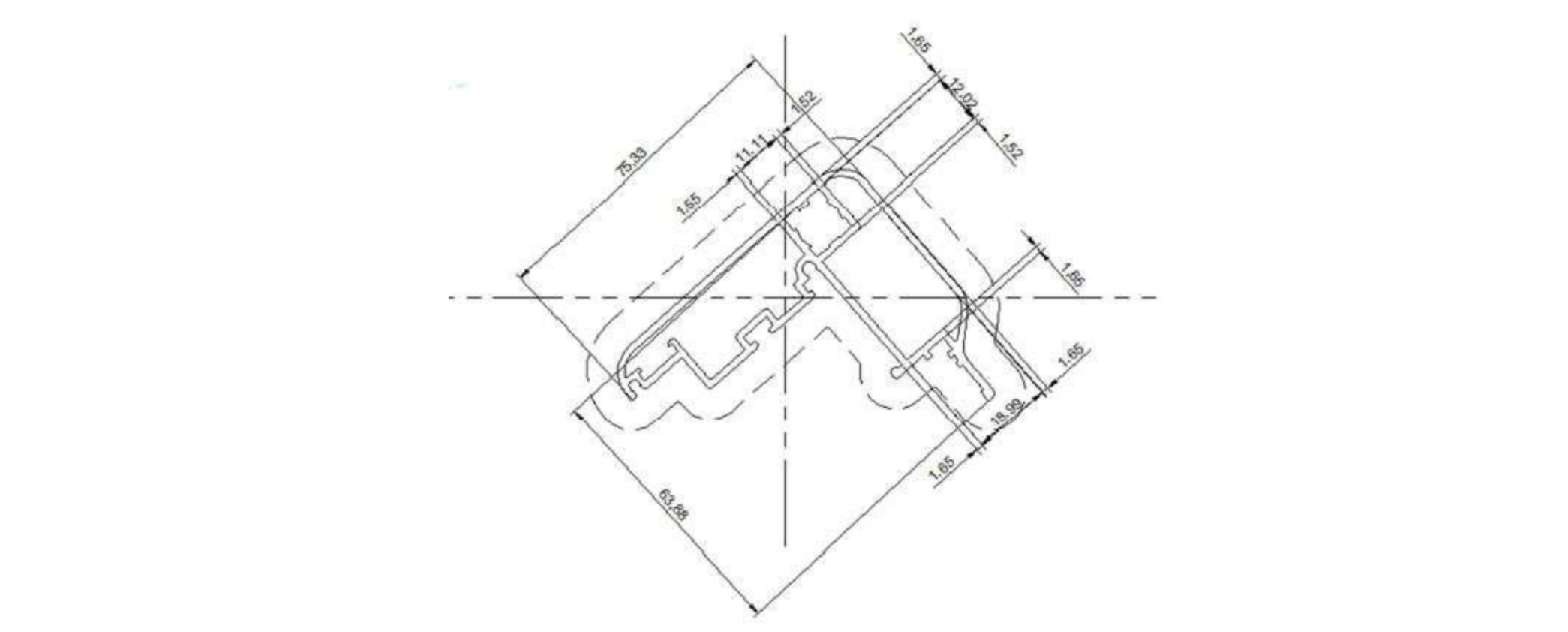
Fig. 1. The industrial multi-hollow profile.
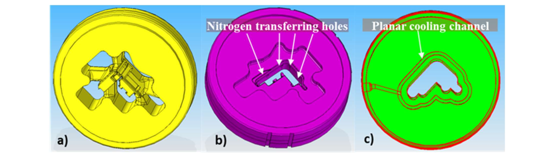
Fig. 2. The tooling set: a) The mandrel; b) The die; c) The backer with the planar
cooling channel.
Five thermocouples K-type were used to monitor the thermal field in the tooling set (Fig. 3): two in the mandrel (T2, T4) in the proximity of the welding chamber where high deformations are imposed to the material and three in the die (T1, T3 and T5) nearby the bearing zones to evaluate the efficiency of the cooling where the highest temperature are reached.
Ten AA 6060 billets, with a diameter of 205 mm and a length of 790 mm, were extruded with a ram speed of 2.71 mm/s in different conditions of nitrogen flow rate. A conical taper heating of 499-445 °C (front-back) was applied in the billet along its axis. Temperatures of 427 °C and 413 °C were set for container and ram, respectively, while a die pre-heating of 490 °C was imposed. Fig. 4 reports the temperature history of the thermocouples during the experimental test together with the exit profile temperature acquired with a pyrometer placed out of the press (orange line). Neglecting the extrusion of first billet used to homogenize the temperature in the tooling set, subsequent five billets were extruded in uncooled condition achieving the stationarity at the sixth billet. Billets 7 and 8 were extruded with the 100 % of nitrogen flow rate, with an inlet coolant pressure of 2 bar and an inlet temperature of -200 °C, data provided as reference by the nitrogen plant supplier. Billet 9 and 10 were extruded with 30 % and 20 % of nitrogen flow rates, respectively, in order to evaluate the performances of the selected channel design with a reduced nitrogen consumption.
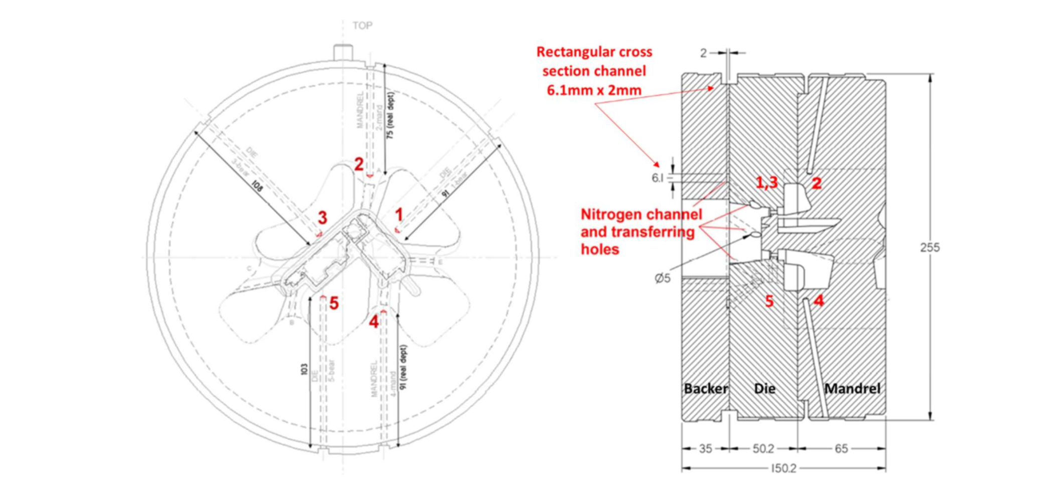
Fig. 3. Positioning of thermocouples: T1, T3 and T5 in the die; T2 and T4 in the mandrel.
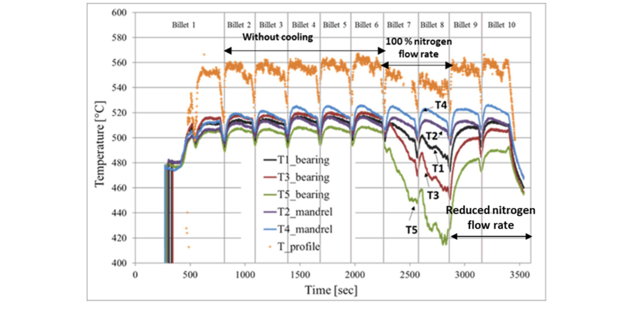
Fig. 4. Temperature history of the thermocouples in the tooling set during the experimental campaign.
In the uncooled process, the exit profile temperature reached a value of 560 °C, while thermocouples T1, T3 and T5 in the die recorded a peak temperature of 518 °C, 520 °C and 510 °C, respectively, lower than that of the exit profile due to the distance of thermocouples of about 15 mm from the bearing zones in the extrusion direction. In the proximity of the welding chamber, thermocouples T2 and T4 registered a maximum temperature of 517 °C and 525 °C, respectively. In terms of process load, a peak of 19.1 MN was recorded in the uncooled process without significantly differences from billet 4 to billet 6.
During the extrusion process of billet 8 with 100 % of nitrogen flow rate, the exit profile temperature decreased of 20 °C (from 560 °C to 540 °C), in relation to the effect of the cooling in the die and the small contribution of the gas atmosphere at the profile way out. In the die, the drop of temperatures was remarkable, recording a maximum decrease of 80 °C in the thermocouple T5 (from 510 °C to 430 °C), while temperatures of 490 °C and 460 °C were acquired by thermocouple T1 and T3 compared to 518 °C and 520 °C of the uncooled condition. In the mandrel, the drop of temperatures was negligible and below 10 °C in both thermocouples, with a positive relapse on the deformability of the billet nearby the welding chamber. The localized cooling in the die did not cause a significantly increase of the extrusion load with a value of 19.9 MN against 19.1 MN of the previous condition. In the ninth extrusion with the 30 % of nitrogen flow rate, temperatures immediately rose again to higher values obtaining, in thermocouple T5, a temperature of 480 °C against the 430 °C reached with the maximum flow rate. Similarly, the exit profile temperature increased of about 10 °C. In the last extrusion, the 20 % of nitrogen flow rate was not enough in terms of cooling effectiveness, obtaining a thermal condition comparable to the uncooled one.
In this experimental campaign, the liquid nitrogen cooling showed its potentiality in terms of heat removal rate with only a slightly increase of extrusion load. On the other hand, the data acquired by the thermocouples highlighted the limit of the this channel design in terms of balancing of the thermal gradient in the bearing zones. Indeed, the three thermocouples in the die recorded about the same temperature during the uncooled process, while great differences were detected with nitrogen cooling (Fig. 4). In addition, the selected design showed a significantly reduced cooling effectiveness with valve opened lower than 100 %, thus limiting the handling of the nitrogen consuming. The use of FEM for the design of the cooling channel could provide a support to obtain an optimal cooling solution, thus limiting the time consuming and the costs of the experimental campaign with improper cooling system design.
3 Numerical Modelling of the Extrusion Process with Nitrogen Cooling: Implementation and Validation
COMSOL Multiphysics® 5.4 is a commercial code that allows to couple different modules for a complex multiphysics analyses such as thermo-fluid dynamics and thermo-structural problems [14]. In the present work, the code has been used to perform a 3D thermo-fluid dynamics study of the extrusion process integrated with a 1D analysis of the die nitrogen cooling. The 1D modelling of the cooling channel reduces the calculation of the thermal and fluid dynamics variables to the middle line of the cooling path but allows to set the geometric characteristic of the channel section as well as the concentrated pressure drop within the channel. In addition, the heat transfer coefficient is not considered constant along the cooling path [13-14] thus suggesting a reliable evaluation of the cooling efficiency of the channel design combined with a substantial reducing of computational time.

Fig. 5. FE model: a) The billet and the tooling set; b) The 1D cooling channel integrated in the tooling set.
In Fig. 5, the generated FE model is shown with the tooling set combined into a single tool to reduce the mesh elements and the billet in the already-extruded configuration according to the pure Eulerian numerical approach. The latter allows to replace the container and the ram by equivalent boundary conditions in terms of thermal and load contributions, thus reducing the number of elements composing the mesh and the computational time. Within the tooling set, the 1D cooling channel was integrated, as showed in Fig. 5b.
For the validation of the numerical model, the experimental stationary data of the sixth billet, for the uncooled condition, and of the eighth billet for the cooled one, were selected. Specifically, in Table 1 are reported the numerical input parameters in terms of initial temperatures and boundary conditions set accordingly to the experimental data. In this model, the hot aluminium was treated as a fluid with high viscosity depended on the share rate and temperature, while the flow stress was modelled with the Sellars-Tegart inverse sine hyperbolic law [15]. In the contact areas between the billet and the tooling set, a sticking friction condition was generally imposed, while in the bearing zones the slip friction condition was used. The thermal properties of the nitrogen were set as a function of pressure and temperature [16], using a high heat transfer coefficient around the boiling point in order to account for the heat removal during the phase change. However, in terms of density, the nitrogen was considered as liquid within the channel.
Table 1. Process parameters and Nitrogen properties set in the numerical model.
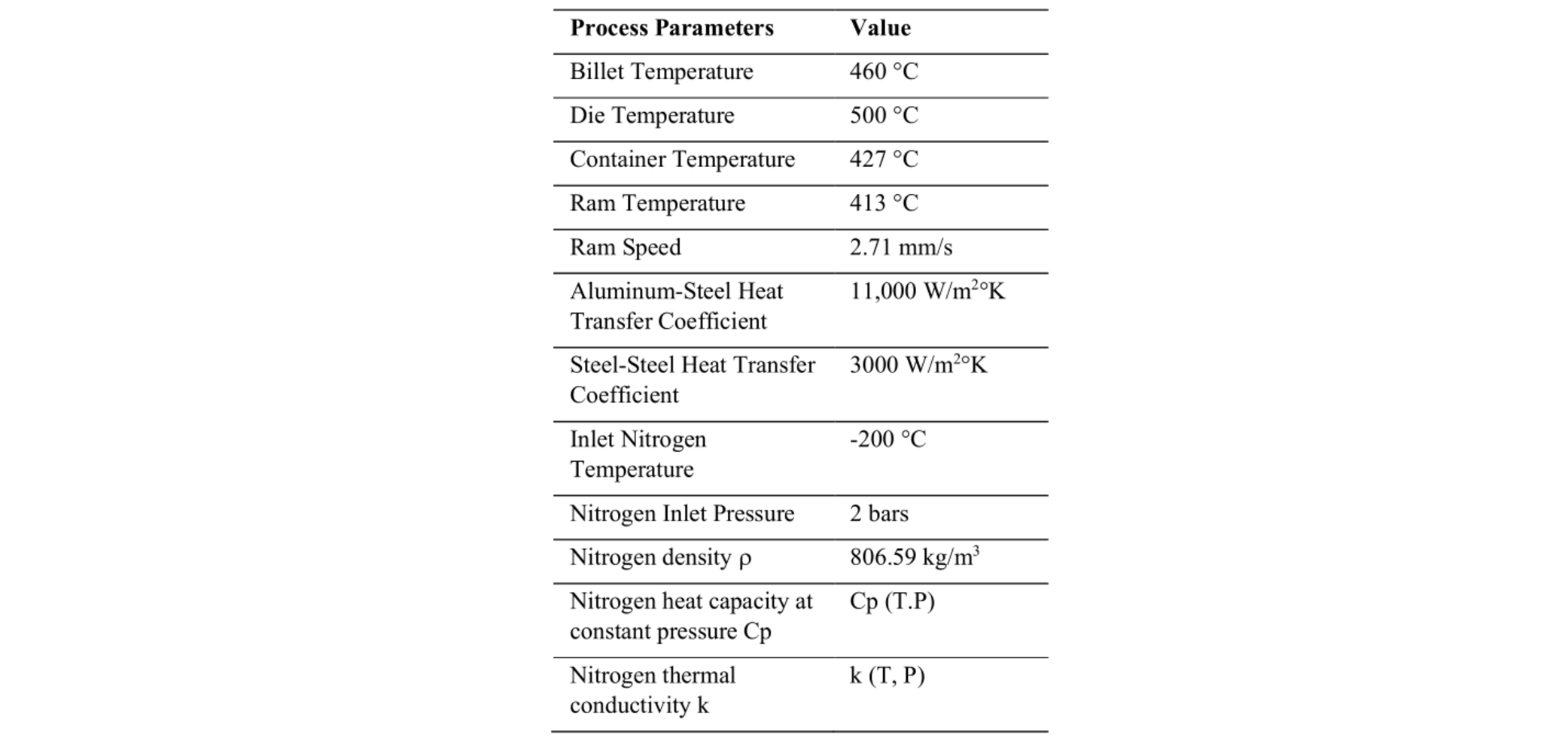
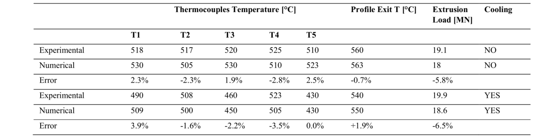
Fig. 6 and 7 show the thermal maps in the thermocouples planes in uncooled and cooled conditions in the mandrel and in the die, respectively. In the process modelled without cooling (Fig. 6a and 7a), a slight overestimation of the die temperature (T1, T3 and T5) was observed, while a general underestimation of mandrel temperature (T2 and T4) was found. However, the results reported in details in Table 2 return errors below 3 %, confirming the goodness of the numerical predictions. In terms of extrusion load, the underestimation of 6 % is considerably acceptable.
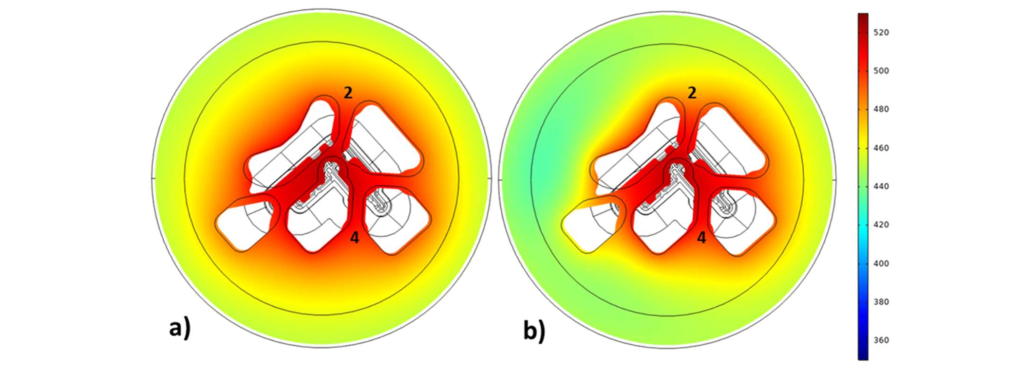
Fig. 6. Thermal field in the thermocouple plane of the mandrel: a) Uncooled process; b) Cooled process.
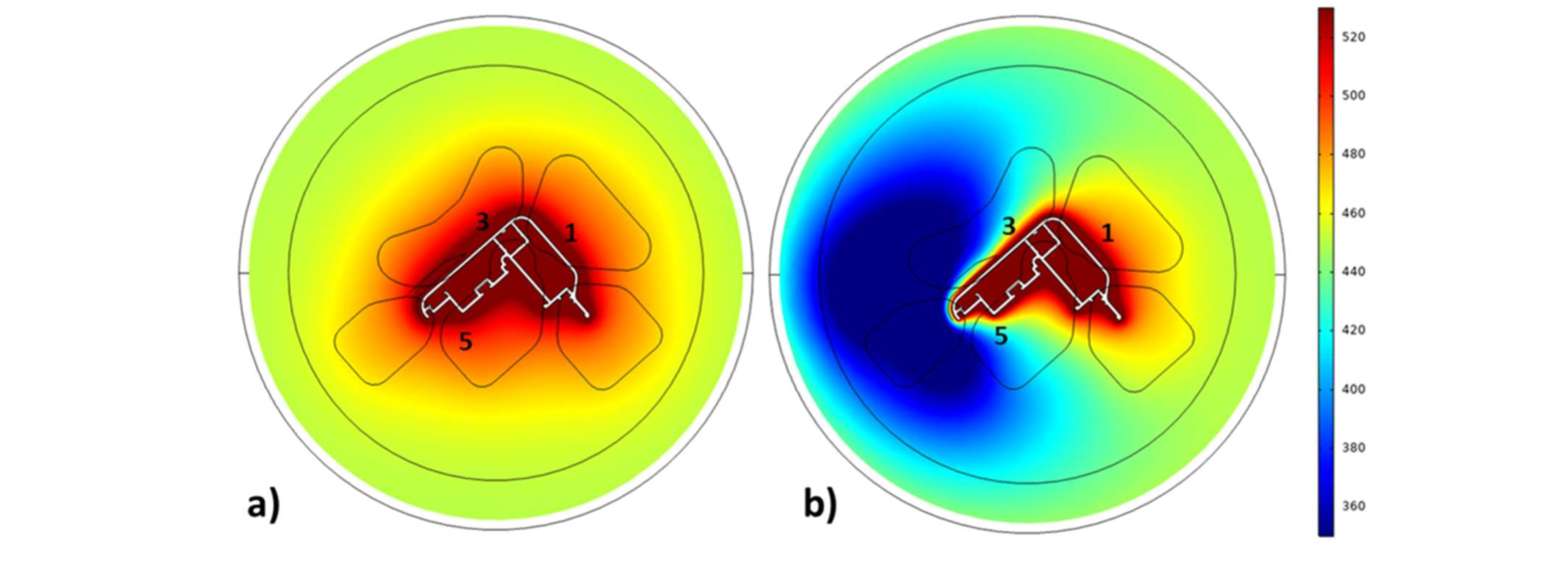
Fig. 7. Thermal field in the thermocouple plane of the die: a) Uncooled process; b) Cooled process.
Table 2. Experimental-Numerical comparison in terms of temperature and load evaluation (Billet 6 and Billet 8).
In Fig. 8 and Table 3 are reported the numerical results with the 20 % of nitrogen flow rate, that showed an ineffective cooling as emerged by the experimental campaign.
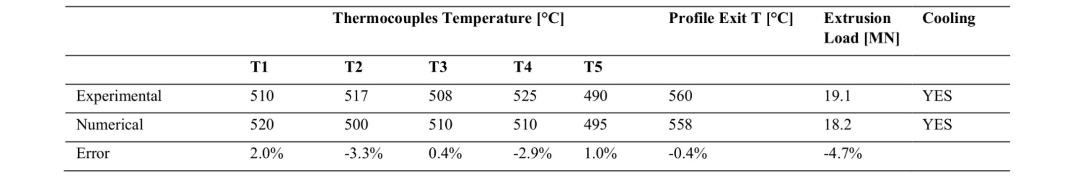
Table 3. Experimental-Numerical comparison in terms of temperature and load evaluation with 20 % of nitrogen flow rate (Billet 10).
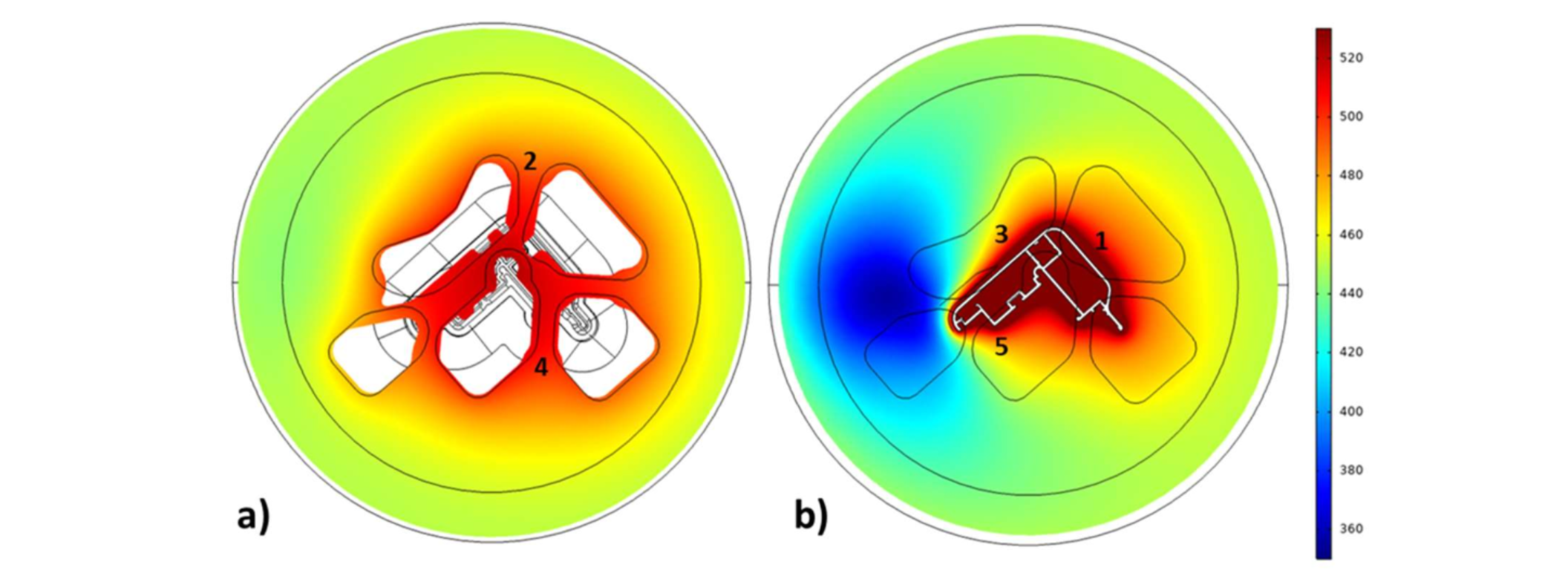
Fig. 8. Thermal field in the thermocouple plane with 20 % of nitrogen flow rate: a) Mandrel; b) Die.
Therefore, the numerical analysis brought to reliable results in terms of thermal and load predictions, showing the low cooling of the mandrel, the unbalanced cooling in the die and the small increase of the extrusion load with the nitrogen cooling. In the next paragraph, the capabilities of the 1D numerical model are shown in terms of rapid re-design of the cooling channel with the aim to achieve a balanced thermal field in the die and an effective cooling reducing the nitrogen consumption.
4 Numerical Re-Design of the cooling channel
In order to obtain a balanced cooling around the profile and bearing zones, two designs are proposed (Fig. 9). In the first design (Design 1 in Fig. 9b), the cross-section area of the channel is doubled at the top of the planar path, while in the bottom part it is decreased of 50 % (from 6.1mm x 4 mm to 3 mm x 2 mm). This should force the nitrogen to flow towards the region of thermocouple T1, not cooled in the original design. For the same reason, the diameter of the transferring holes was reduced from 5 mm to 2.5 mm in order to promote the flow within the planar path instead of toward the outputs.
In the second design (Design 2 in Fig. 9c), the inlet channel and the top part of the planar path have a rectangular cross section increased of three times with respect to the original design, the bottom part has the original measures and the outlets have the same diameter of 2.5 mm as for Design 1. This solution aims to promote an efficient balanced cooling with low valve opening, reducing the pressure loss within the channel.
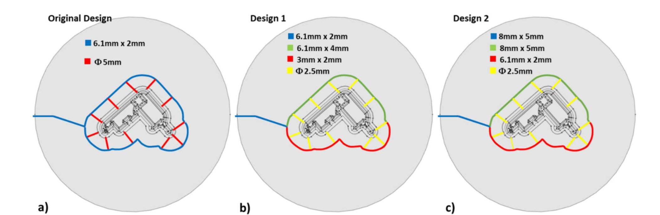
Fig. 9. Re-designs of the cooling channel: a) Original Design; b) Design 1; c) Design 2.
In Fig. 10, the thermal map of the die achieved with the Design 1 is compared with that obtained with the original design. In this case, the temperatures around the profile are more homogeneous, obtaining a value of 430 °C in all thermocouples loci of the die. In both cases, with the maximum available inlet pressure of 2 bars, the nitrogen flow rate was the same and equal to 8 l/min.
In terms of temperature drop, a decrease of 80 °C around the profile could be detrimental in terms of die life. Therefore, a flexible handling of the nitrogen flow can be required for a better control of the die thermal field.
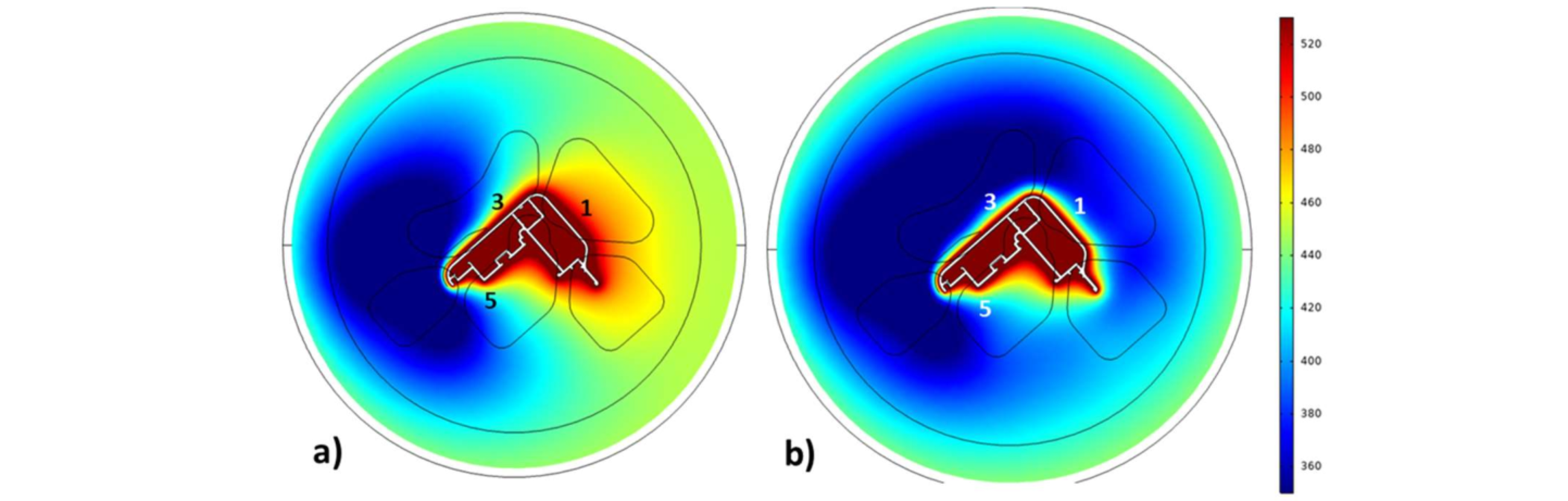
Fig. 10. Thermal field in the thermocouple plane of the die with the 100 % of nitrogen flow rate: a) Original Design; b) Design 1.
Fig. 11 compares the three channel designs thermal performances with the nitrogen valve opened at 20 %. Design 2, with reduced pressure losses, allows to double the nitrogen flow rate with the same inlet pressure if compared to the other designs. In this way, with the 20 % valve opening, it shows a more balanced cooling, recording a temperature of 450 °C in the three thermocouples, against the unbalanced solution of Design 1 (490 °C in T3 and T5 and 505 °C in T1).
Despite the increase of nitrogen flow rate at the same inlet pressure, Design 2 guaranteed this efficient balanced cooling using a flow rate reduced from 8 l/min (obtained by the other designs with 100 % valve opening) to 4 l/min, thus reducing the nitrogen consuming.
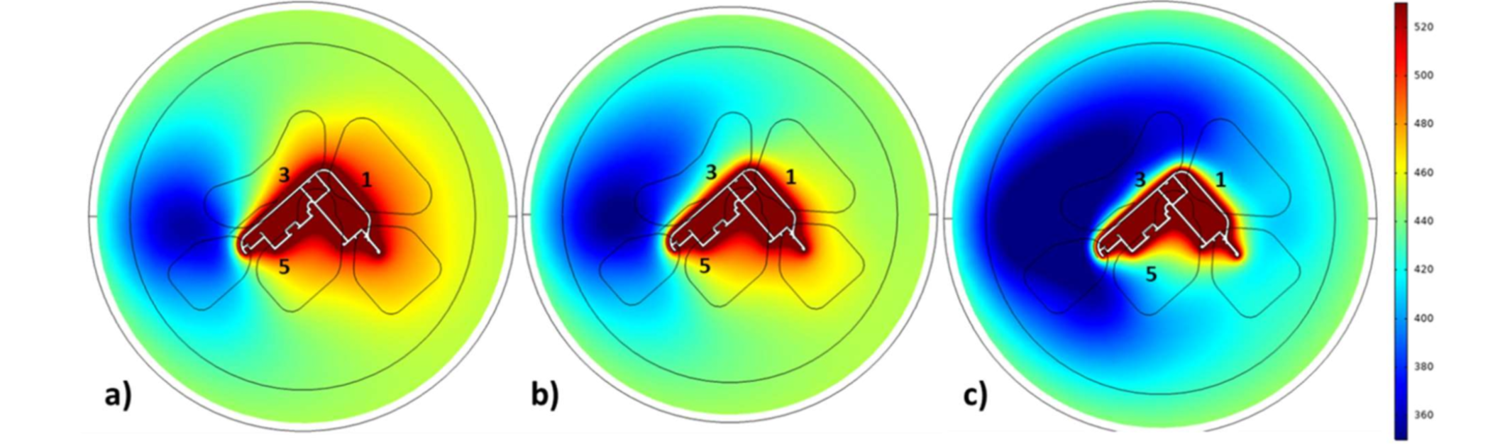
Fig. 11. Thermal field in the thermocouple plane of the die with 20 % valve opening: a) Original Design; b) Design 1; c) Design 2.
5 Conclusions
The experimental campaign performed on an industrial AA6082 aluminum profile extruded with a nitrogen cooled die evidenced the efficiency of the solution obtaining a drop of 20 °C in the exit profile temperature and a peak drop of 80 °C in the die, nearby the bearing zones. However, the unbalanced thermal field in the die cannot be considered acceptable for the die life and profile soundness.
The 3D numerical model of the extrusion process integrated with the 1D model of the cooling channel showed a good predictability in terms of temperatures and loads with experimental-numerical discrepancies always below 7 %. In addition, the low computational time of the simulations allowed a rapid re-design of the cooling channel. The first re-design with the maximum nitrogen flow rate of 8 l/min showed a balanced cooling around the bearings zones obtaining a temperature of 430 °C in all thermocouples of the die. The second re-design reduced the pressure losses within the channel and it guaranteed an efficient balanced cooling with a flow rate of 4 l/min, promoting a better handling of the nitrogen flow.
It can be then concluded that the proposed 1D numerical model allows achieving a solution in a reasonable computational time and the adjustments in channel geometry and process variables can be easily iterated to find an optimal design within the pre- processing stages, perfectly matching with the requirement of supporting the die design phase in an industrial framework.
