1 Introduction
The market for additive manufacturing materials is actively developing as additive manufacturing equipment is modernised to meet new consumer demands. New materials as well as common thermoplastics with relatively well-studied properties - ABS (acrylonitrile butadiene styrene) and PLA (polylactide), adapt to the most common technology of 3D printing - FDM (Fused Deposition Modelling) technology [1] or FFF (Fused Filament Fabrication) [2], which consists in layer-by-layer deposition of material in the form of thread (filament) according to the original program. Note that ABS and PLA thermoplastics, are widely used for 3D printing of objects without special requirements for material properties.
To date, there are a huge number of known options for the filament technology FFF for the relevant user tasks, including engineering plastics, designed to solve applied problems. The study of a set of properties of engineering thermoplastics for 3D printing using FFF technology has attracted the attention of many researchers due to the need to achieve an optimal combination of material properties in printing, sufficient to meet the operational requirements for the finished product [3].
Thermoplastic PETG which is gaining popularity in additive manufacturing is formed by adding glycol to PETG. Glycol modification helps to retain the amorphous structure and consequently prevents crystallisation of the PETG polymer material and its brittleness. That is why PETG plastic is considered to be more durable than classical PET, and also than ABS and PLA plastics, the study of properties of which is devoted to a sufficiently large number of works [4-7], including those considering post-processing of products obtained by FDM/FFF technology [8].
Overall, PETG is characterised by a unique combination of mechanical [9], optical, structural and performance properties. Regarding the environment, PETG is recyclable and reusable, which increases its value by reducing the cost of the product it makes.
PETG samples exhibit low gloss and high transparency. This property is a priority when using PETG in the arts and crafts to create transparent and translucent products or in orthodontics to produce aligners using the vacuum-forming technique [10]. PETG is non-toxic, which makes it suitable for industries such as food and medicine, particularly dentistry [11]. PETG plastic has a high resistance to alkalis and acids, which makes it much more difficult to post-treat. For example, isopropyl alcohol, which can clean and treat a sample of ABS plastic, will affect PETG plastic in such a way that the sample becomes cloudy in colour and softer than originally.
When considering the use of PETG in additive manufacturing, it should be noted that its properties are affected by the 3D printing mode chosen when implementing the FFF technology. Not much attention has been paid to this issue. There are data on the effect of specimen orientation during 3D printing on mechanical properties [12], on the effect of PET plastic type on mechanical properties [13], and on the effect of long-term exposure to chemicals on the quality of PETG products [14]. It is important to note that often the mechanical properties of the printed specimen are not understood as properties of the material itself, but as properties of the specimen structure, which introduces some confusion in the interpretation of tensile test results. A detailed study of this phenomenon was carried out by the authors of [15].
In this regard, the purpose of this work is to conduct a set of studies on laboratory samples of PETG plastic, aimed at determining the modes of processing PETG plastic by FFF technology and the subsequent post-treatment, which allow to maintain high mechanical properties and transparency of the material. Post-treatment with chemical reagents (solvents) is one of the trends in additive manufacturing and is associated with changing only the surface of the filament without disturbing the shape of the final product.
The paper shows the solution to several problems: 1) investigation of mechanical properties of transparent PETG laminate from different manufacturers taking into account sample orientation during 3D printing and scale factor; 2) investigation of influence of chemical solvent (dichloromethane) on mechanical properties of transparent PETG laminate and its transparency; 3) investigation of influence of chemical solvent (dichloromethane) on optical properties of transparent PETG laminate.
2 Materials and Equipment
Several tests were planned and carried out to meet the objectives of this study, including: 1) uniaxial tension test of transparent PETG plastic specimens; 2) chemical solvent (dichloromethane) resistance test of transparent PETG plastic specimens; 3) permeability test of transparent PETG plastic specimens by spectrophotometry. The second test was combined with an uniaxial tension test and a permeability test.
The uniaxial tension test and the bandwidth test were performed at Technopark “Slava” using the following equipment: universal testing machine 50ST Tinius Olsen and spectrophotometer SF-2000.
The test specimens were produced on Anycubic 4Max Pro 3D-printer, which implements FFF technology. Anycubic 4Max Pro 3D-printer has a closed printing area (thermal chamber), which ensures high quality of manufactured products and product size repeatability during 3D-printing.
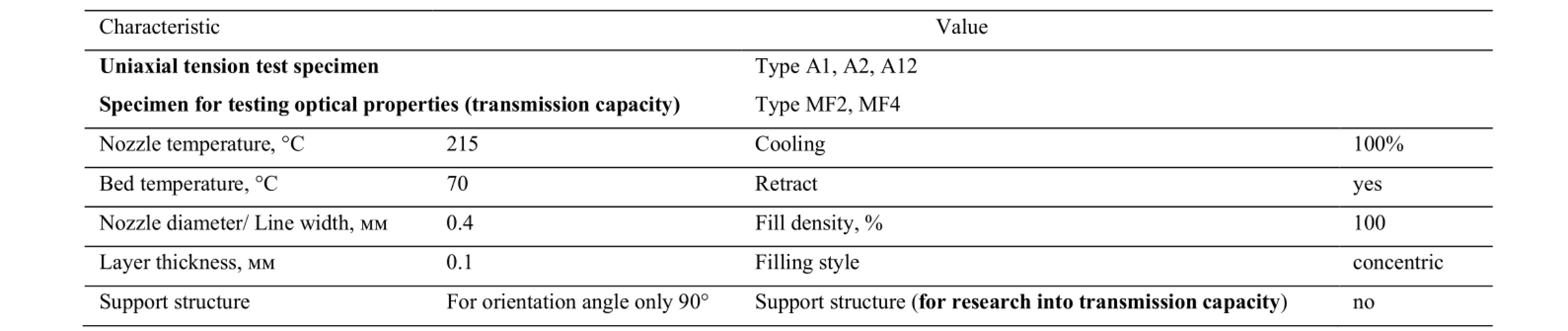
The shape of the uniaxial tensile specimens and for the examination of optical properties are shown in Fig. 1 and 2, respectively; the dimensions of the specimens are shown in Table 1. Sample sizes for mechanical properties testing are chosen based on GOST 11262-2017 and GOST 33693-2015. Table 2 presents the 3D printing parameters for each of the test specimen types.
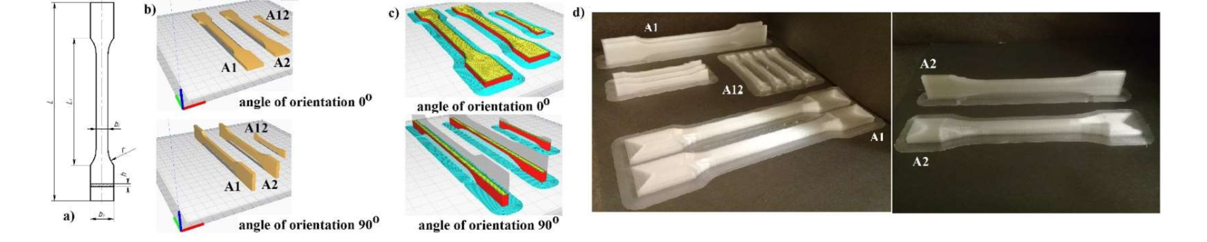
Fig. 1. Tensile test specimens. (a) general view of the specimen, (b) orientation of the 3D printed specimen type A1, A2, A12, (c) filling of the cross-section of the 3D printed specimen, (d) appearance of the printed specimens type A1, A2, A12.
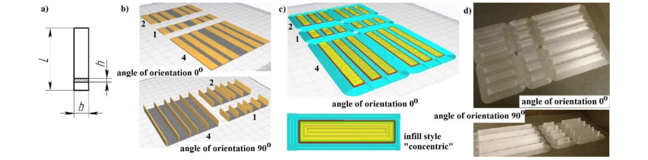
Fig. 2. Specimens for optical properties testing. (a) general view of the specimen, (b) orientation of the specimen during 3D printing, (c) filling of the section of the specimen during 3D printing, (d) appearance of the printed specimens.
Tensile specimens were oriented on the working table of the 3D-printer at an angle of 0 ° and 90 °. With this method of specimen fabrication, the material itself, rather than the contact surface of two adjacent layers, is subsequently worked in tension [15]. All samples were 100 % filled with the concentric style (see Fig. 1d). The chosen filling style, in addition to the chosen angle of the specimen, allows the mechanical properties of the material itself to be evaluated in the tensile test. This is in accordance with the recommendations and conclusions presented in [16].
Table 1. Specimens characteristics.
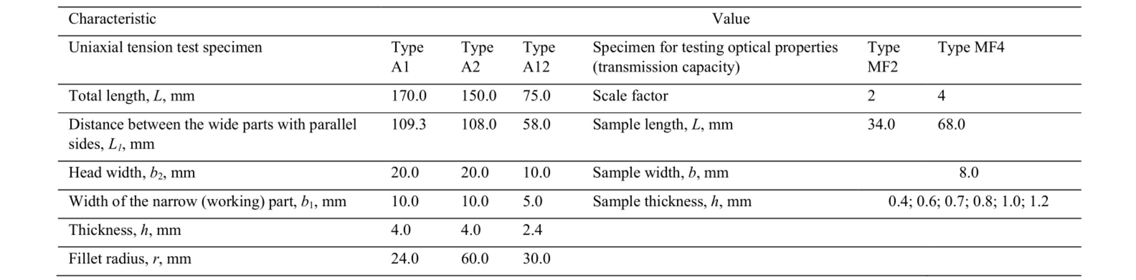
The samples for the optical properties study were also oriented on the 3D printer's worktable at 0 ° and 90 °. This was necessary to assess the effect of the orientation of the product on the 3D-printer's workbench on the optical properties of the material. The second parameter that was taken into account in the development of the samples was the scale factor (see Table 1), which makes it possible to study the optical properties of the printed material on samples with different product wall lengths. In this case, the product wall has different thicknesses (see Table 1) and is formed in one pass of the 3D-printer's print head.
Table 2. Parameters of specimens’ 3D-printing.
Finally, a few words about the PETG material used to make the samples described above (see Fig. 1, 2). In the study of mechanical properties, the material for 3D-printing PETG with a diameter of 1.75 mm from five Russian manufacturers was considered: My3d (Moscow, Russia), FDPlast (Moscow, Russia), GEEKfil/lament (Klin, Russia), NIT (Volgograd, Russia), ABSMaker (Moscow, Russia). The examination of the optical properties was limited to the following PETG brands: My3d (Moscow, Russia), GEEKfil/lament (Klin, Russia), NIT (Volgograd, Russia).
3 Experimental procedure
The in-situ experiment deals with three tasks: 1) investigating the mechanical properties of transparent PETG from different manufacturers, taking into account the scale factor and orientation of the sample during 3D printing; 2) investigating the effect of chemical solvent treatment (dichloromethane) on the mechanical properties of transparent PETG; 3) investigating the effect of chemical solvent treatment (dichloromethane) on the optical properties of transparent PETG.
The plan of the full-scale experiment aimed at solving the first problem involves the production of samples (see Fig. 1) of five grades of PETG plastic. Two types of samples are printed from each laminate - A1, A12; in addition, samples of type A2 were also produced from NIT, ABSMaker , My3D laminates only.
The working length on the initial specimen, Lр , is determined before each tensile test and is equal to the distance between the upper and lower grips of the testing machine (Fig. 3). The recommendations for 3D printing the specimens presented in Section 2 were also taken into account in preparing the experiment.
After 3D printing, each specimen was clamped in the grips of a 50ST Tinius Olsen test machine and tensile tested until failure, recording the force and displacement of the upper grip to determine the relative elongation and tensile strength (ultimate tensile strength).
The plan of the in-situ experiment, aimed at solving the second problem, involves the use of previously manufactured samples and their surface chemical treatment with dichloromethane under two regimes: dipping and spraying. The duration of surface dichloromethane treatment is a few seconds, which does not lead to material degradation of the sample. After the surface chemical treatment, the specimens are dried and subjected to tensile fracture on a 50ST Tinius Olsen test machine and the relative elongation and tensile strength (ultimate tensile strength) determined.
The plan of the in-situ experiment, aimed at solving the third problem, involves making samples (see Fig. 2) from three grades of PETG plastic. Two types of samples are 3D printed from each plastic - MF2, MF4. The dimensions of the samples are shown in Table 1. During the preparation of the experiment, the recommendations for 3D printing samples presented in Section 2 are also taken into account. Part of the samples of each type are surface chemically treated by dipping and spraying.
The prepared and prepared samples are placed in special optically transparent cuvettes and placed in a spectrophotometer. The samples are then irradiated on the spectrophotometer "SF-2000" with light at a wavelength of 300 nm to 1100 nm.
From the data obtained at a wavelength of 650 nm the values of two parameters are determined for each plastic - optical density (D, units) and transmittance (T, %). Calculation of parameter values is carried out automatically in software of spectrophotometer SF-2000.
Results of in-situ experiments, their systematization and discussion are presented in Section 4; an example of specimens after testing is shown in Fig. 4.
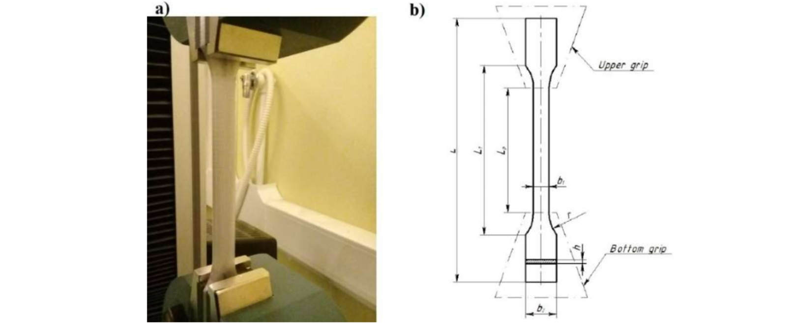
Fig. 3. Positioning the specimen in the working area of the testing machine 50ST Tinius Olsen. (a) general view of the specimen in the machine grips, (b) scheme for measuring the working length of the original specimen.
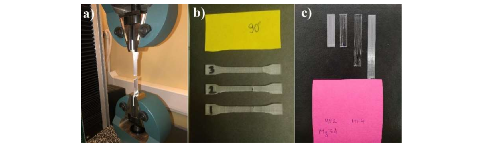
Fig. 4. Example of specimen appearance after the test. (a) tensile specimen type A1 of NIT, (b) tensile specimen type A12 of NIT, (c) surface chemical treatment of specimen type MF2 and MF4 of My3d.
4 Results and Discussion
4.1 Influence of orientation angle and scale factor on mechanical properties
A study of the mechanical properties of PETG in five brands shows a variation in the ultimate strength of the material (see Fig. 5). Analysis of the data shows that samples of the same plastic made with different scale factor (e.g. samples A1, A12, A2 of PETG plastic and samples of ABSMaker plastic (see Fig. 5) have different tensile strength values. And this trend is observed at either of the two selected sample orientation angles when printing.
Type A12 is preferred as it provides the smallest variation in ultimate strength at different orientation angles and for different PETG grades (see Fig. 5). The data shown in Fig. 7 is the first time that such a comparison, taking into account the scale factor and the orientation angle, has not been made before.
As the scale factor has little influence on the test results, in the next step the type A2 PETG samples of the brands FDPlast, GEEKfil/lament, ABSMaker were not manufactured and therefore not investigated.
4.2 Effect of chemical treatment on mechanical properties
The next stage of the study examined the effect of surface chemical treatment on the mechanical properties of PETG samples of five grades (see Fig. 6).
The trend noted in section 4.1 in the variation of the tensile strength depending on the PETG grade, sample type (A1, A12, A2) as well as the orientation angle (0 or 90) is maintained. The overall level of the tensile strength decreases (see Fig. 6) to about 20 % of the level observed in samples not chemically treated prior to stretching.
Thus, PETG tends to soften under the influence of the chemical dichloromethane. This feature of PETG is also indicated by the results of [14].
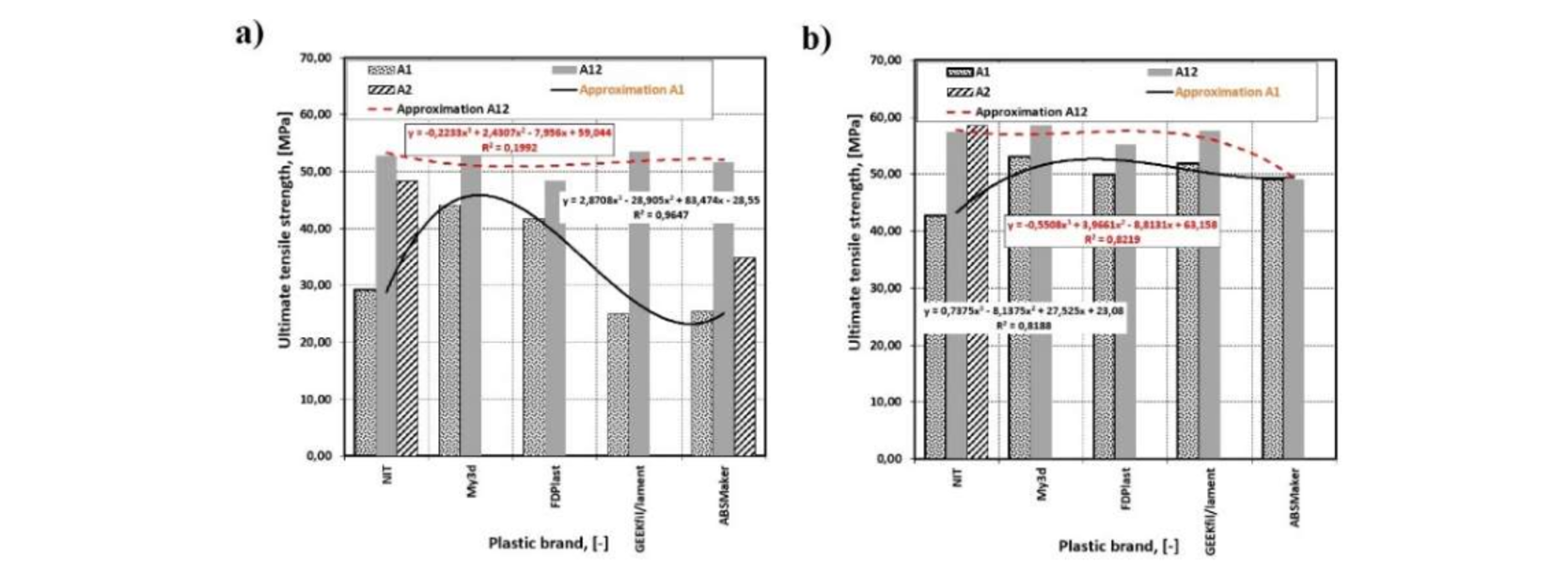
Fig. 5. Mechanical properties of the PETG without surface finishing treatment. (a) angle of orientation 0 °, (b) angle of orientation 90 °.
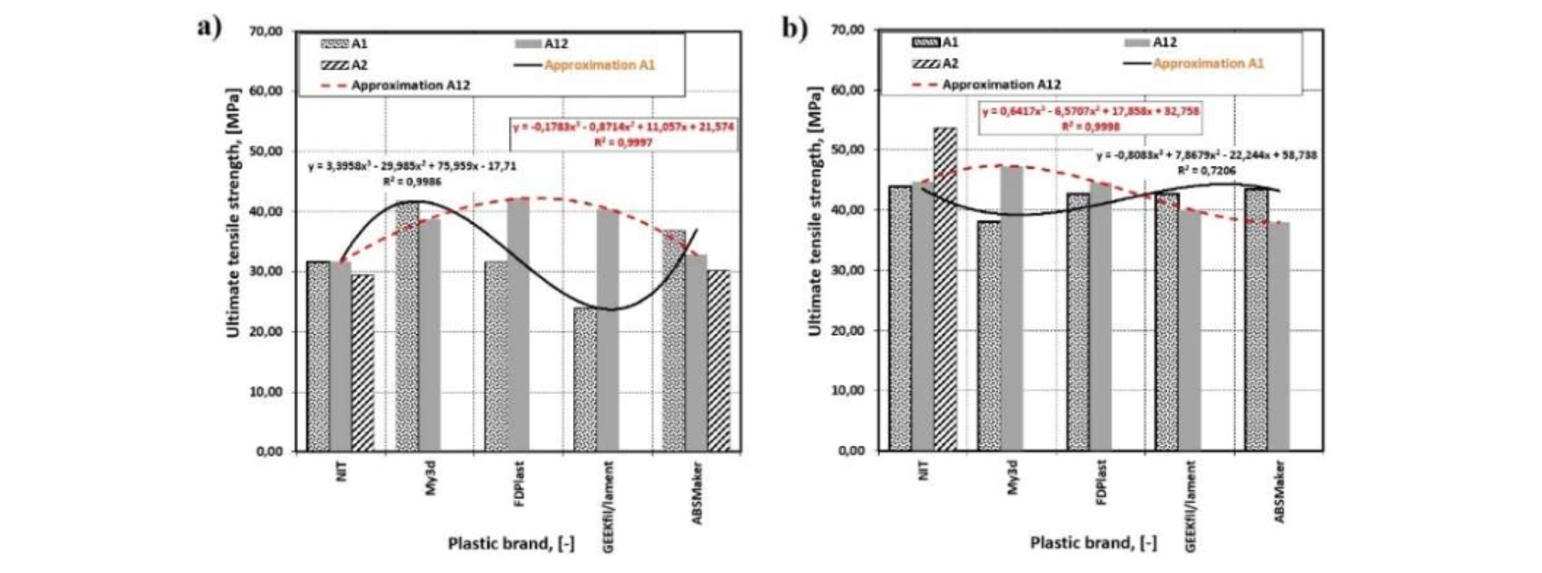
Fig. 6. Mechanical properties of the PETG with surface finishing treatment.
(a) angle of orientation 0 °, (b) angle of orientation 90 °.
From a practical point of view, the most significant results are presented in this section. Two types of surface chemical treatment of the plastic under investigation with dichloromethane were considered. The treatment duration was fractions of a second to protect the laminate from irreversible degradation [14].
Fig. 7-10 show plots of the dependence of optical density (D) and transmittance (T) on the thickness of the samples (see Fig. 3). Two types of plastic samples ( MF2 (8*34), MF4 (8*68) ) were irradiated with wavelength 650 nm. In the absence of any surface chemical treatment (see Fig. 7 and 8) the dynamics of the D and T parameter do not differ significantly between samples made of NIT and My3d plastic.
Depending on the type of sample (MF2 or MF4) and the angle of orientation of the sample at printing, its transparency as determined by the transmittance value does not exceed 25 % and 28 % for NIT laminate (see Fig. 7) and My3d laminate (see Fig. 8) respectively. The maximum transparency value is achieved with a reduction in sample thickness, which agrees well with numerous practical observations of 3D printing with FDM/FFF technology.
The surface treatment by dipping leads to a significant increase in transparency (see Fig. 7b and Fig. 8b). The sample becomes practically transparent (see Fig. 4).
Surface treatment by spraying results in a less significant increase in transparency (see Fig. 9b and Fig. 10b). The transmission coefficient is approximately 25-50 % lower than in the case of the dipping treatment of plastic samples (see Fig. 9b and 9d; Fig. 10b and 10d). Although spray treatment produces a more uniform treatment of the bulk sample, it requires additional conditions to ensure that the treatment is controlled over the entire volume for maximum effect.
It is also interesting to compare the transmittance values (see Fig. 7-10) obtained for the NIT and My3d samples with the transmittance of PETG laminates used for thermoforming applications such as e.g. aligners. Additional PETG Gasket Splint GS030 samples (manufacturer 3A Medes) were made for this comparative analysis.

Fig. 7. Optical properties of the PETG specimens made of NIT plastic. (a) change in optical density of NIT plastic, (b) change in transmittence of NIT plastic.
This laminate has a thickness of 0.80 mm and 1.00 mm and is suitable for cutting specimens that are 8 mm wide and 68 mm long. The transparency results of these samples showed that with a thickness of 0.80 mm, the transmittance was 88.15 %; with a thickness of 1.00 mm it was 87.96 %, i.e. an average of 31.8 % higher than that of the printed samples (see Fig. 9-10).
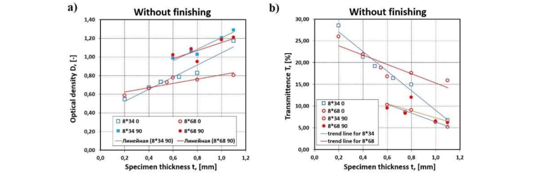
Fig. 8. Optical properties of the PETG specimens made of My3d plastic. (a) change in optical density of My3d plastic, (b) change in transmittence of My3d plastic.
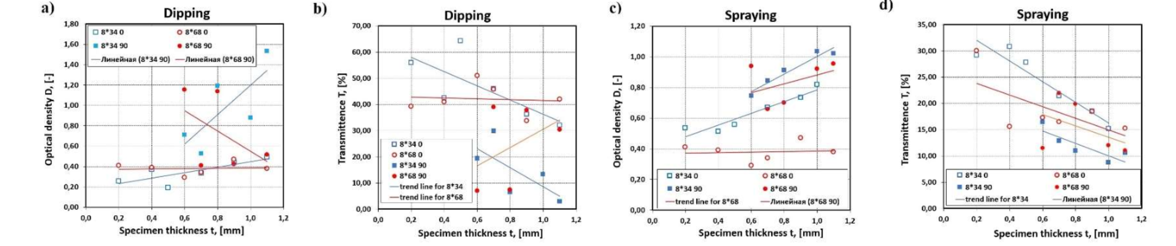
Fig. 9. Optical properties of the PETG specimens with surface finishing treatment made of NIT plastic. (a), (c) change in optical density of NIT plastic, (b), (d) change in transmittence of NIT plastic.
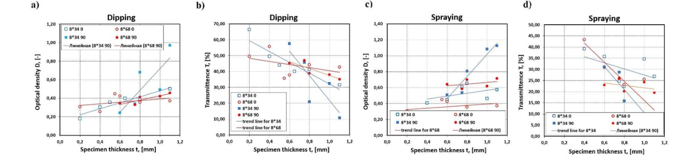
Fig. 10. Optical properties of the PETG specimens with surface finishing treatment made of My3d plastic. (a), (c) change in optical density of My3d plastic, (b), (d) change in transmittence of My3d plastic.
5 Conclusions
The research carried out and the analysis of the results allow the following general conclusions to be drawn:
-
PETG plastic is characterised by a unique combination of properties: mechanical, optical, structural. This provides its application in various fields, including medicine, food industry etc.
-
The mechanical properties of PETG change with the sample orientation angle during 3D printing by approximately 10-20 % depending on the plastic manufacturer. The most suitable specimen type printed from PETG for tensile testing is type A12 (see Table 1).
-
The mechanical properties of PETG can be changed by surface chemistry treatment of 3D printed FDM/FFF products. A short-term surface chemical treatment leads to a decrease in the tensile strength of PETG without degradation.
-
The optical properties of printed transparent PETG samples can be improved by surface chemical treatments such as dichloromethane. The transmittance at wavelength 650 nm is about 66 %, depending on the orientation angle, thickness of the sample and its size (see Fig. 7-10). Comparison of the transmittance of the printed PETG specimen with the T-value of a 0.8-1.0 mm thick laminate for thermoforming aligners shows that the difference is approximately 31.8 % in favour of the thermoforming laminate. This, in turn, suggests the potential for further study and refinement of PETG laminate processing regimes using FDM/FFF technology.
