1 Introduction
The reduction of greenhouse emissions is an important challenge for the society today and for the future. Consequently, there is extensive research effort in areas of manufacturing technology to decrease the resource consumption of the mobility sector. A major influence on the efficiency of a vehicle has its weight. In order to reduce the vehicle mass, multi-material systems are used which consist of different materials and geometries. The installed components of such a system in a vehicle body have different mechanical properties and are adapted to the local requirements. Thus, different materials and geometries have to be joined for the production of the modules. Due to the increasing challenges for the joining technologies, conventional methods reach their process limits and new methods are required. A possibility to respond to the increasing requirements is the use of combinations of multiple existing processes to combine their individual advantages. A frequently used method for joining different components is self-piercing riveting, however, this joining technology is inflexible and can only react slightly to disturbances and process variations. In order to be able to react versatilely to changing conditions, an adaptation of the conventional joining process is necessary. One process of the forming technology that has many possibilities to influence it by its characteristics is tumbling. Due to the flexible movement of the tumbling punch, an increased material flow control is possible and tailored joints can be produced which are adapted to the requirements. The extension of process limits through the integration of a tumbling punch has already been demonstrated in clinching [1], and is to be transferred to self-piercing riveting. To illustrate the possibilities and challenges of this process combination, the two processes, are described in the following.
2 Tumbling self-piercing-riveting
2.1 Tumbling
Conventional tumbling is based on the historical development a bulk metal forming process with a reduced contact area between punch and work piece compared to conventional upsetting, but it is also used in joining technology, for example in riveting and clinching [1]. The deformation of the workpiece is achieved during tumbling by applying a forming process incrementally. Due to the predominant compression stress during tumbling, the process can be assigned to the pressure forming processes according to [2]. The basic working principle is a punch axis tilting out of the tool axis by the tumbling angle, as shown in Fig. 1 b). However, it must be ensured that the centre of rotation of the punch is on the workpiece or on the surface of the joining element. The contact surface between punch and work piece is reduced by the adjustment of the punch and a partial forming and rotating movement results. Increasing the tumbling angle causes a reduction of the contact surface and thus a decrease of the necessary forming force. According to [3], significant reductions in the forming force are recognisable up to a tumbling angle of α = 10°; beyond this, it can no longer be identified [3].
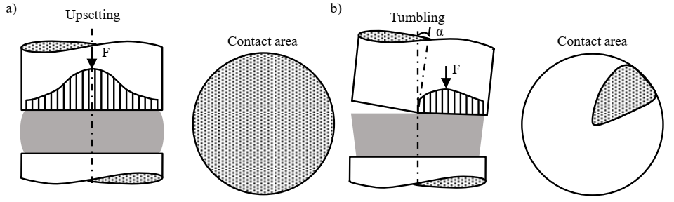 Fig. 1. Process characteristics contact surface and normal stress for a) upsetting and b) tumbling [4]
According to [5], the reduction of the forming force during tumbling relative to a conventional process is between 20 % and 65 %, however, it depends heavily on the contact surface and the forming process. The contact area itself is reduced to 20 % to 30 % in a tumbling forming process [6].
The tilted punch and the incremental deformation during tumbling cause a different stress state and a different deformation than conventional upsetting. During conventional upsetting, an axial and radial material flow occurs in the workpiece. The radial component increases the diameter and the axial material flow reduces the height of the component. Furthermore, the friction between workpiece and punch impedes the radial material flow on the workpiece surface. The inner part of the workpiece is formed to a greater extent and results in a barrel shape. This effect causes the unevenly distributed stress state over the workpiece as shown in Fig. 1 a). The maximum stress occurs in the centre and decreases with rising radius towards the outside [7].
A tumbling forming process shown in Fig. 1 b) causes a conical body, which has its bottom surface on the punch side. The stress is distributed comparatively homogenous on the workpiece and the maximum stress is also lower due to lower frictional properties as the tumbling movement causes a rolling friction instead of a sliding friction as in upsetting [8]. However, it is important to consider that a tangential material flow occurs in addition to radial and axial flow. Furthermore, with incremental forming larger degrees of plastic strain can be achieved [9], but an increased process time must be accepted [8].
2.2 Self-piercing riveting
According to DIN 8593, self-piercing riveting is a joining by forming process that requires no pre-piercing operation, which considerably reduces the necessary positioning accuracy for the joining partners and does not cause any structural changes in the joining zone compared to welding [10]. The joining process enables parts with different mechanical properties and geometries to be joined, such as hybrid components consisting of aluminium, steel and synthetic materials. By setting a joining point with self-piercing riveting, a connection is created which is both an interference fit and force fit [7]. Fig. 2 a) shows the process of self-piercing riveting with the individual process steps and process components.
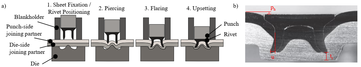 Fig. 2 a) Self-piercing riveting process and b) microsection of a self-piercing riveting joint
In Fig. 2 b) a microsection of a self-piercing riveting joint is shown with the important quality criterions of rivet head end position ph, base thickness tr and interlock u. The maximum force levels during this joining process are approx. 100 kN for the punch and about 5 kN for the blankholder depending on the combination of joining partners and rivet [11].
A limitation of conventional self-piercing riveting is that the geometry of the die and rivet depends on the specific joining task. For process-safe joining, each new joining application requires sampling and experience on the operators part. It is therefore a very rigid process, which can only react limitedly to process variations and disturbing variables. To extend the process limits for joining with auxiliary joining elements, a combination of self-piercing riveting with the previously presented forming process tumbling is presented.
2.3 Process combination
The process combination of tumbling and self-piercing riveting shown in Fig. 3 b) is intended to unite the process properties of both processes and to create possibilities for a versatile manufacturing of joints. As self-piercing riveting is a comparatively rigid process, the properties of tumbling will significantly increase the process parameters that can be adjusted during the process. In Fig. 3 a) a tumbled self-piercing riveting joint with the tumbling punch and the resulting normal stress is shown.
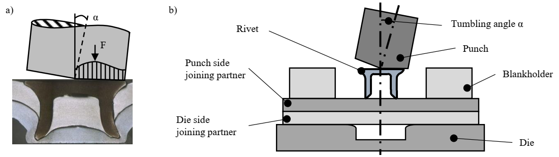 Fig. 3 a) Tumbling self-piercing riveting with microsection and b) schema
Due to the flexible process route design, joining connections can be adapted to the requirements. Different connections can be joined without changing the tools and, on the one hand, be able to react to process fluctuations and, on the other hand, be able to manufacture joints with different sheet thicknesses and materials with one punch-die combination. These so-called tailored joints are thus to be produced by a versatile process with targeted adaptation of the process parameters. Possible applications are combinations of higher-strength steels and aluminum alloys as well as the increase of the process-related maximum joinable sheet thicknesses. The flexible tumbling kinematics enables a targeted material flow control during the three process phases of cutting, flaring and upsetting. In this way, the quality features of undercut, residual base thickness and rivet head end position of a semi-tubular self-pierce rivet joint can be formed in a targeted design and guarantee high joining point quality and process robustness. With the help of increased material flow control, material can be locally accumulated in failure-critical areas and the load-bearing capacity can be increased in cross and shear tension loads. A further possibility is the production of joints with more than two joining partners or a joining partner made of a different material. Furthermore, it should be noted that the process force could be considerably reduced by tumbling. For the joining tools in industrial applications, an integration of a tumbling punch is necessary, but the stiffness of the joining tools can be reduced. Summarizing the process characteristics the rigid conventional joining process of self-piercing riveting gains considerably in flexibility and versatility through the integration of a tumbling process. The possibilities of joining operations and the in-situ influence are increasing, which opens up new technological fields for self-piercing riveting. For the investigation of a self-piercing riveting with a tumbling punch, numerical investigations are first necessary to identify process requirements for a joining tool. In addition, first insights into the material flow and the controllability of such a process combination can be gained. For precise results of the investigations and for the evaluation of the results it is important that the properties of the materials are well known. Therefore, two sheet metal materials in form of an HXT590X+Z and an EN AW-6014, which are typical for the automotive car body construction and a rivet material 38B2, are characterised and the investigation methods and results are presented in the following.
3 Material characterisation of a self-piercing riveting process
The HCT590X+Z is a galvanised dual phase steel that is well suited for use in the automotive industry. Despite its high tensile strength, the steel has a comparatively good formability and can therefore be used for components with complex shapes. As second material, an aluminium alloy of the type EN AW-6014 is investigated. The material also has been developed for automotive components and is characterised by good formability. It is used for critical exterior closure panels but also for demanding inner applications. The rivet material 38B2 H4 is a hardened tempered steel, which is available as extrusion material with a diameter of 5.2 mm and has the same process history as the rivet elements, except for the forming of the auxiliary joining elements.
To determine the characterisation methods, a basic understanding of the processes is necessary. In the case shown here, however, it is a combination of two processes. Therefore, it has to be considered that there are interactions of the process properties and the processes influence each other. Thus, possible effects can be amplified, cancelled or not influenced by themselves. Due to the tilting of the tumbling punch, there are considerable differences in the stress states and changes in deformation compared to conventional self-piercing riveting. The rotating movement causes, in addition to the axial and radial flow of material, as it occurs during conventional upsetting, a tangential material flow. Furthermore, during tumbling it must be noted that the strain and material flow is greater on the punch side of the workpiece than in the centre. Therefore, the strain changes with the height of the rivet over the whole process. Also, the torque introduced by the rolling friction has an influence on the stress and strain of the whole process. Furthermore, the state of stress oscillates over the workpiece, means that the workpiece is loaded and unloaded with each rotation of the tumbling punch. Tumbling and upsetting have different stress distributions on the work piece. During axial upsetting, the smallest plastic strain occurs in the centre of the work piece and the highest at the edge, whereas tumbling has its highest plastic strain rates on the work piece surface and the lowest in the workpiece centre as well.
For the characterisation of the materials of the sheet metal and rivet material, the prevailing stress states during the joining process must be taken into account. Fig. 4 shows b) the stress state of a conventional self-piercing riveting and c) the resulting plastic strain.
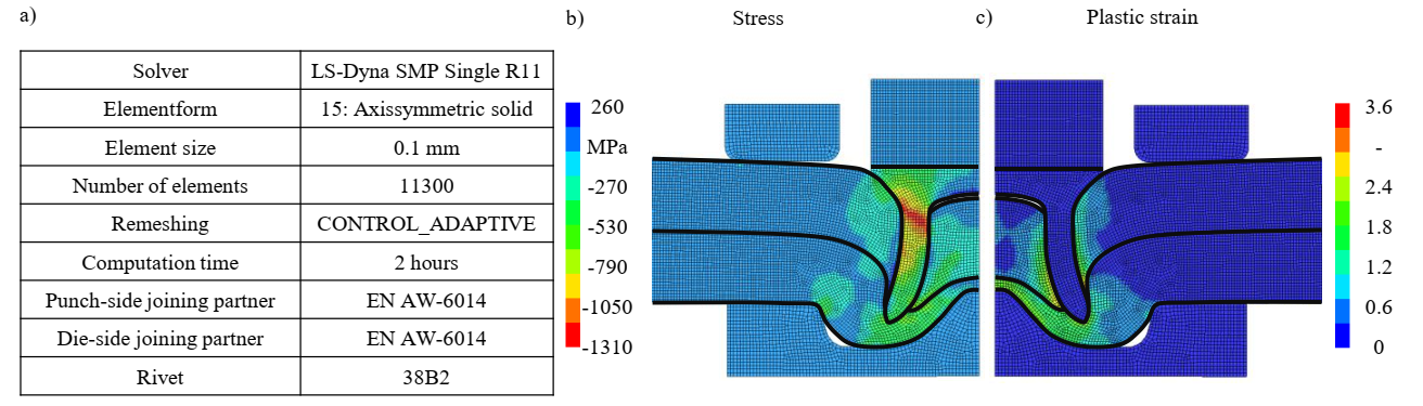 Fig. 4 a) Investigation setup b) shows the stress state of a conventional self-piercing riveting and c) the plastic strain
The stress state shows both tensile and compressive stresses. It is evident that the rivet element is mainly exposed to compressive stresses. Only at the shaft of the rivet, low tensile stresses are visible due to the flaring effects for forming the undercut of the joint. For this reason, the rivet material is characterised with an upsetting test setup, shown in Fig. 5 a).
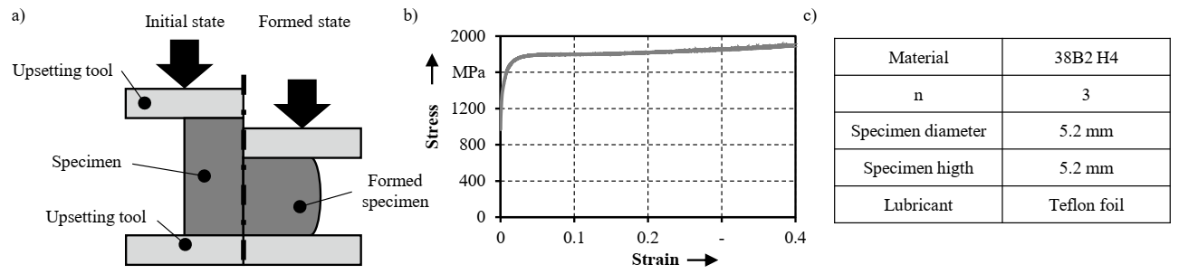
Fig. 5 a) Process for upsetting with resulting b) flow curve of 38B2 H4 and c) testing parameters
This test method fits very well, due to the compressive stresses states during the investigation. The height to diameter ratio was set to 1 and is therefore in the same range as the geometry of the rivet. The plastic strain is comparatively low with a maximum value of 0.4 since the deformation of the rivet is only the spreading to form the undercut. For the flow curves, no extrapolation is necessary, since strain levels up to 0.4 can be achieved with an upsetting test. In Fig. 5 b) the resulting flow curve of the material 38B2 is shown.
The two joining partners in the form of the sheets are exposed to compressive and tensile stresses. However, no predominant load can be identified. Although the absolute maximum compressive stress is higher than the absolute maximum tensile stress, the material is exposed to tensile stress in areas that are important for the joining point quality. This occurs in the areas of the sheet metal directly around the rivet as well as in the die-side joining partner in the area of the die. Since these areas are important for the resulting joint quality, tests with tensile stresses are chosen for the characterisation of the sheet material. Furthermore, the characterisation of sheet metal is difficult in an upsetting test due to the available geometry of the material in sheet form.
A widely used method for characterising tensile stresses is the tensile test according to DIN 6892-1 [12], shown in Fig. 6 a). With this test, strains up to 0.8 can be achieved, but only uniaxial stress states are present. To investigate the influence on the rolling direction, samples are taken from the sheet metal plane at 0°, 45° and 90°. Another test method for determining the material properties is the bulge test as shown in Fig. 6 b). By applying pressure to a hydraulic active medium, the round specimen is drawn out of the sheet thickness into the die. This test setup enables greater strains to be achieved and the material can be examined under biaxial tensile stress. By conducting both tests, the uniaxial stress state as well as the biaxial stress state can be modelled for different directions in the sheet plane.
The strain rate, however, shows significant differences between the auxiliary joining element and the joining partners. As a plastic strain up to 0.4 can be determined on the rivet, this is considerably higher at the punch side sheet and reaches values of up to 3.6. For this reason, an extrapolation of the flow curves for the sheet metal material is necessary. In Fig. 6 c) are the extrapolated flow curves for both materials shown. Due to the distinct hardening behaviour of HCT590X+Z, the extrapolation approach according to Swift [13] is used for this purpose. In contrast to this, the extrapolation approach according to Hockett-Sherby [14] is applied for aluminium EN AW-6014, which does after a certain strain not consider any further hardening.
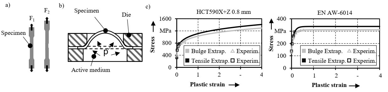 Fig. 6 a) Tensile test b) bulge test c) flow curves of HCT590X+Z and EN AW-6014
The differences in the flow curves can be explained by the hardening of the material and the different extrapolation approaches. For HCT590X+Z, the Swift approach was used, which tends to reach its maximum flow stress only at higher degrees of deformation. In this case, the maximum achievable degrees of deformation are therefore less relevant when carrying out the test. In the case of EN AW-6014, a stronger difference between the test methods can be identified. Due to the lower achievable strain with the tensile test, the extrapolation approach leads to an earlier hardening compared to the bulge test with higher attainable strain, because of less measured points of stress and strain during the experiments.
4 Summary and Outlook
The increasing requirements on joining processes make new technologies necessary. One possibility is to combine conventional self-piercing riveting with a tumbling process. As self-piercing riveting is a very rigid process, it is advisable to investigate a combination with a tumbling punch, as tumbling has many parameters, which can be adapted to a process or even changed in the process itself. For this purpose, the two processes were described and a concept of a combination for tumbling self-piercing riveting was presented. The combination should make it possible to produce tailored joints because the integration of tumbling significantly increases the versatility of self-piercing riveting and allows an improved reaction to process and disturbance variables.
In order to be able to investigate the concept in more detail, numerical investigations are necessary for which a characterisation of the joining partners and the rivet is necessary. For this purpose, the rivet material 38B2 is characterised with an upsetting test and the sheet metal HCT590X+Z and EN AW-6014 with tensile and bulge tests.
Based on these results, numerical investigations on tumbling self-piercing riveting can be carried out. In a first step, investigations on the material flow are conceivable as well as the investigation of the influence of the tumbling kinematics on the joint. Further, the investigation of the sheet material with a layer compression test is intended.
Acknowledgements
The author would like to thank the German Research Foundation for their support. This work was funded by the Deutsche Forschungsgemeinschaft (DFG, German Research Foundation) – TRR 285 C02 – Project-ID 418701707.
