1. Introduction
In manufacturing technical products, the number of parts and their complexity including diverse combinations of dissimilar materials increased. Modern design concepts have driven a trend towards multi-material design in sense of weight reduction as well as sustainability [1]. A well-known example is the integration of fiber-reinforced plastics such as tubes and plates made of natural fibers [2]. Fiber-reinforced plastics feature high specific stiffness. Metals feature high strength and ductility to be shaped into small complex parts that can be exposed to multidimensional load. The combination of both materials bears high potential for weight reduction at reasonable costs. As material properties differ between fiber-reinforced plastics and metals, only few joining processes fulfill the demands. A further challenge is the varying geometry (high tolerances) of semi-finished products made of natural fibers - like the inner and outer diameter of tubes.
Most prominent processes are mechanical joining by additional elements like screws or rivets or adhesives for bonding operations. Additional elements have a negative effect on the force transmission caused by an interruption of the fibers [3]. Adhesive bonding is a time-consuming process at least caused by diverse requirements as surface cleaning and/or surface treatment. Due to ageing, the strength of the bond may decrease [4]. Hydraulic joining of tubes by force fit was researched by Groche and Tibari in [5], where a Tshaped connection was achieved by axially forming one of the tubes into the end of the other tube. The force fit was realized by compressed material in the joint zone which deflects elastically in order to crease a force fit. Joining by forming is a promising approach for joining tubes to sheets of dissimilar material. Alves et al. introduced a novel method for joining tubes to sheets by deformation of the tube [6]. In the process, the sheet metal was prepared with a hole and high forces were used to deform the tube locally. Stresses occurred at the hole, which may lead to failure. Furthermore, stamp and forming kinematic must neatly be fitted to the semi-finished product.
In the field of impulse forming technologies, various special processes have been developed for tube-to-tube or sheet-to-sheet joining of dissimilar materials. Beneath a modified material behavior and material flow, this high-speed forming simplifies tooling as described by Langstädtler et al. [7]. Joining of tubes was well investigated for electromagnetic forming by Weddeling et al. [8]. The influence of different mandrel geometry on torsion force transmission was investigated. Electromagnetic clinching was performed using a conical mandrel to guide the material flow transverse to the initial impulse direction for filling the interlock [9]. Laser shock joining of thin sheets was investigated by Veenaas et al. [10]. In addition, impact welding of tube-to-tube and sheet-to-sheet is possible by impact of an accelerated flyer part on a target. Here, various pulse technologies such as laser shock or electromagnetic impulse can provide the driving force [11]. By impact welding, a material-closed joining is possible. Electrohydraulic forming was used for joining by clinching of sheet metals [12].
A novel application of electrohydraulic forming is introduced here as high-speed joining by forming aluminum sheet metals to aluminum tubes by creation of a form-fit. This combination of same materials for basic studies was carried out in order to reduce the influencing effects while at the same time enabling to understand the material flow using the high ductility of aluminum. By applying shock waves as an adaptable punch, geometrical and mechanical requirements on joining partners were reduced. The mechanical joint was realized by generating an interlock between sheet and tube. An important question to be answered here was, how this interlock was gained and how it could be influenced by process parameters and how the interlock influences the strength of the joint. The joints were analyzed by microsections and head tension tests. With this, process kinematics and the material flow were investigated.
2. Materials and Methods
Electrohydraulic forming is a high-speed process, which is based on a force transmission via a working medium (here distilled water). The set-up principle and CAD-view of the set-up is shown in Fig. 1 a). A capacitor bank was loaded to a certain loading voltage U0 to vary the supplied loading energy EC. By short-circuiting the capacitor bank through an aluminum wire (diameter of 0.3 mm, length of 20 mm), the vaporization of the wire was initiated and resulted in a plasma. Shock waves in the pressure chamber transferred the forming energy to the sheet metal. The sheets were formed into the tubes ends, see Fig. 1 b). To enable an interlock geometry, the tube ends were modified by diameter reduction from 16 mm to an inner diameter of Di ≈ 14.9 mm. Furthermore, the tubes were deburred at the inner edge. By placing a mandrel inside the tube, the interlock volume was limited. In addition, the mandrel influenced the process kinematic - sheet metal movement - to force the material flow in x-direction.
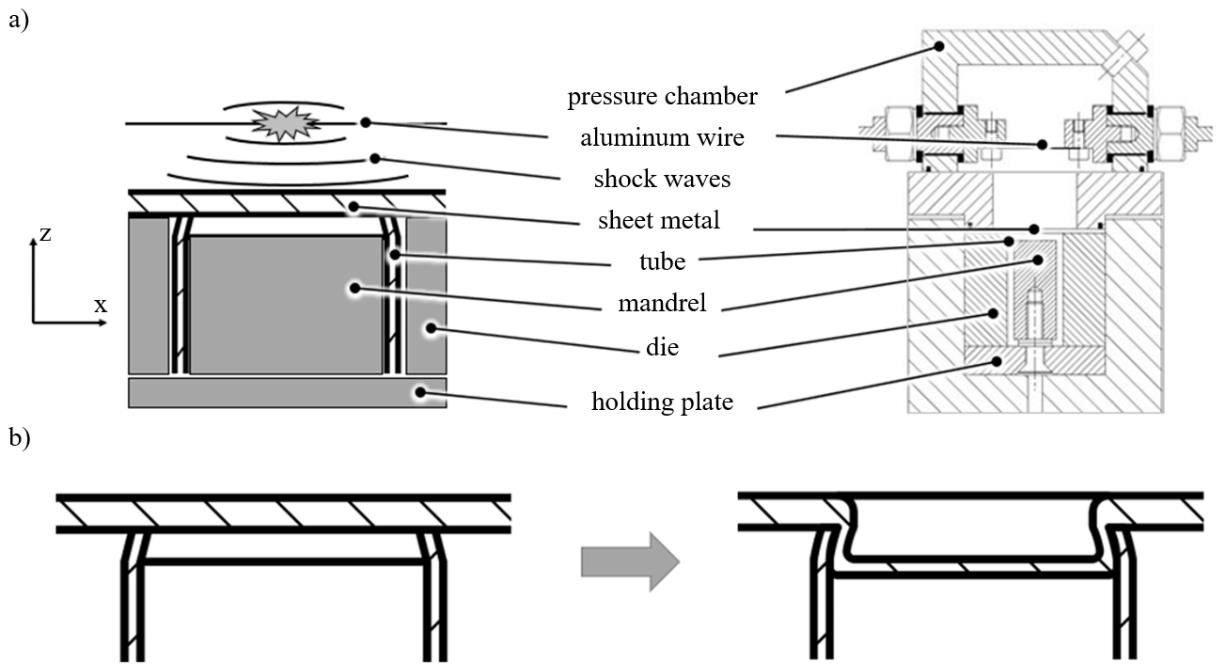
Fig. 1. Electrohydraulic joining of sheets with tubes; a) set-up principle and CAD-view, b) schematic form-fit connection sheet-to-tube.
One decisive feature of the simplified tool design was the temporary integration of the tool. The additionally applied mandrel improved the formation of the joint. The mandrel was mounted in the die. The relative position to the upper end of the tube was set by spacers between mandrel and holding plate.
The joining was performed for EN AW-1050 aluminum alloy (Al99.5) sheets to EN AW-6060 aluminum alloy tubes. Experimental investigations were carried out with variation of the values - loading energy Ec, mandrel distance d and sheet thickness s0, Fig. 2a. Four tests were carried out for each parameter set. Of these, one joint was used for microsection evaluating the undercut volume. The tubes were pre-treated mechanically by compressing one end in radial direction. Additionally, a thread was formed into the tubes at the other end to enable head tension tests after joining. The tube featured a length of 45 mm, an outer diameter of 20 mm and a wall thickness of 2 mm. It was placed in a die to limit the formable area of the sheet metal to the joining zone. A flat mandrel was placed inside the tube with a distance d to the end of the tube. The sheets with an area of 50x50 mm² and different thicknesses of s0 = 1.0 mm, 1.5 mm and 2.0 mm were placed at the end of tube on the die. The 100 µF- capacitor bank was loaded with U0 = 4 kV, 5 kV and 6 kV resulting in loading energies of Ec = 800 J, 1250 J and 1800 J. Head tension testing was performed by pulling in z-direction and aborted with a drop in force after reaching a maximum in tensile force Fmax. Interlock was analyzed in microsections, Fig. 2b. The interlock geometry was analyzed by measuring the interlock height w, the interlock depth f and the inner tube diameter Di to calculate the interlock volume Vi as given by equation (1). Furthermore, the course of the sheet thickness s(x) depending on position x was measured by post processing from the microsections scanned with a Leica DVM6/M digital microscope.

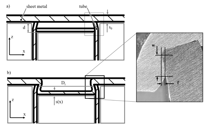
Fig. 2. Joint characteristics; a) varied values, b) measured values.
3. Results
By increasing the supplied loading energy, interlock volume increased (see Fig. 3 and Fig. 4). The material flows from a partial free formable volume by stretch drawing of the sheet metal at the inner tube edge which can be seen in a local reduction of the sheet thickness at inner tube edge. After free forming and bulging of the sheet, the sheet metal hits the center of the mandrel and rolls to the side. The increase of interlock volume for increased loading energy flattens due to strain hardening and further effects related to friction. Furthermore, a widening of the tube ends is observed from a average value before joining of Di ≈ 14.9 mm up to Di (1800 J) = 15.4 mm, that reduces the maximum possible interlock volume. With increase of supplied loading energy also the maximum tensile force increased. The mandrel experienced wear (deformation; abrasive) within the impact area at the mandrel center.
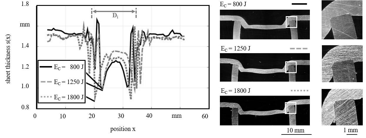
Fig. 3. Sheet thickness profiles for EC = 800, 1250 and 1800 J (d = 3 mm; s0 = 1.5 mm).

Fig. 4. Influence of loading energy EC (s0 = 1.5 mm, d = 3 mm); a) interlock volume Vi, b) max. tensile force Fmax.
In variation of mandrel distance d with constant loading energy EC = 1250 J and sheet thickness s0 = 1.5 mm, an increase of mandrel distance led to an increase of interlock volume as well as maximum tensile force. Due to its strong influence on the joint, the mandrel distance is figured out to be a central influencing value on material flow. A mandrel distance of d = 2 mm resulted in insufficient joining. The joints with d = 3 mm and d = 4 mm showed sufficient strength values. The joints failed by peeling off the interlock and did not fail completely after testing due to stopping before pull out completely. The observation of failure due to shearing of the interlocked material agrees with the correlation of interlock volume Vi and maxium tensile force Fmax see Fig. 5. Highest maximum tensile force was accieved for d = 4 mm. Nearly the same tensile force was reached for d = 3 mm with lower variation. However, these variations are considered to be caused by variations in the preparation of the tube ends (diameter reduction and deburring) as well as a widening depending of process forces. These influences have to be observed in further investigations. The maximum interlock volume was reached for d = 4 mm.

Fig. 5. Influence of mandrel distance d (EC = 1250 J, s0 = 1.5 mm); a) interlock volume Vi, b) maximum tensile force Fmax.
Depending on the mandrel distance, sheet and tube were pressed tightly together which can be as well seen from electric resistance of the aluminum joints with very low R(d = 4 mm) < 0.08 Ω. For mandrel distance d = 2 mm, a small gap was detected which was reduced for d = 3 mm and disappeared for d = 4 mm. Maximum value of interlock depth of f = 0.18 mm was reached for d = 4 mm, whereas f(d = 2) = 0.03 mm and f(d = 3) = 0.16 mm, Fig. 6.

Fig. 6. Microsections of joining results - d = 2, 3, 4 mm (EC = 1250 J, s0 = 1.5 mm).
Besides the mandrel distance, the inner edge radius of the tube is expected to influence the material flow. After free bulging, the sheet metal hit the flat mandrel and rolled to the side. While rolling to the side on the mandrel, the sheet is stretched with local decrease of thickness and material is then pressed from to the inner side of the tube into the interlock volume. This results in a local increase of sheet thickness to s0max. A local increase of sheet thickness was as well detected at the outer gap between tube and die. Both increases are expected to have a positive effect on joint strength due to stiffening and form-fit. The two areas of sheet thickness increase and reductions are clearly visible in the courses s(x) in Fig. 7. The sheet thickness reduction increased with the mandrel distance as more material flow resulted filling the interlock volume. The highest value in thickness reduction was achieved with d = 4 mm.
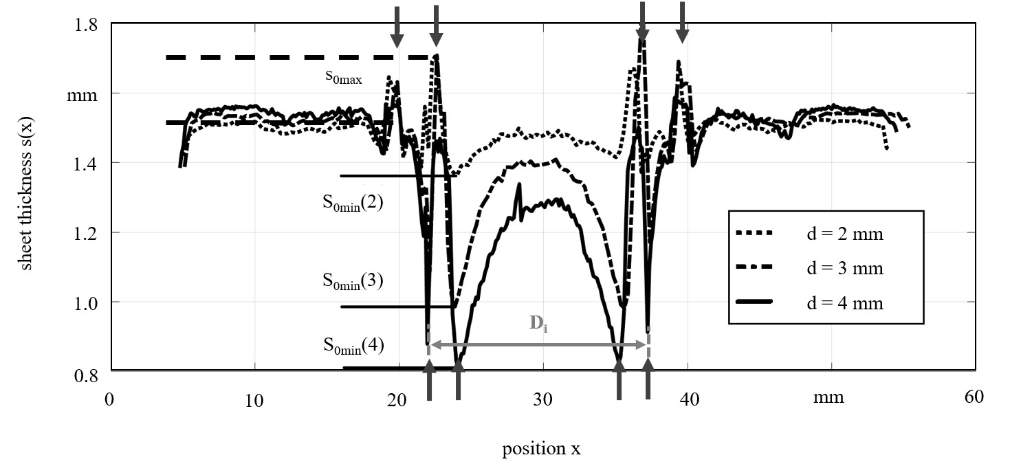
Fig. 7. Sheet thickness profiles for d = 2, 3 and 4 mm (EC = 1250 J, s0 = 1.5 mm).
Correlating the reached maximum tensile forces with the interlock depth, the interlock height and the interlock volume enables a closer look on the holding mechanism, Fig. 8. The maximum tensile force is expected to be influenced by the stiffness of the formed sheet metal and due to the correlation by the interlock volume.
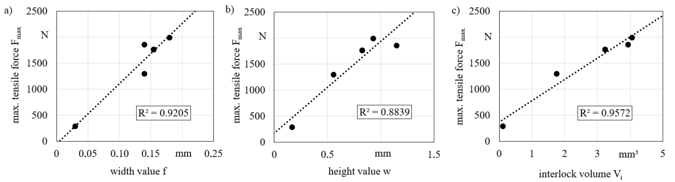
Fig. 8. Correlation due to holding mechanism; a) Fmax (f), b) Fmax (w), c) Fmax (Vi).
Depending on the sheet thickness and material flow, further forming of the sheet and in consequence higher reduction of the sheet thickness (cp. Fig. 9) can reduce the stiffness or even lead to a local failure of the material or at least a change in failure of the joint due to a bending of the joining zone.
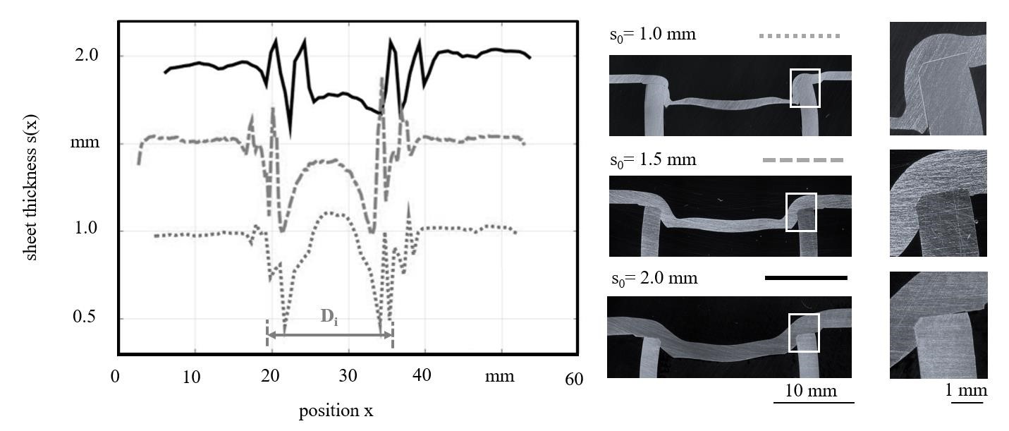
Fig. 9. Sheet thickness profiles for s0 = 1.0, 1.5 and 2.0 mm (d = 3 mm; EC = 1250 J).
This effect was observed in tests for different sheet thickness. However, the interlock volume was very high for thin sheets with s0 = 1 mm, the local high reduction of thickness led to less maximum tensile force, Fig. 10. Hence, an optimum needs to be found for increasing the interlock volume with a reasonable reduction of the sheet thickness.
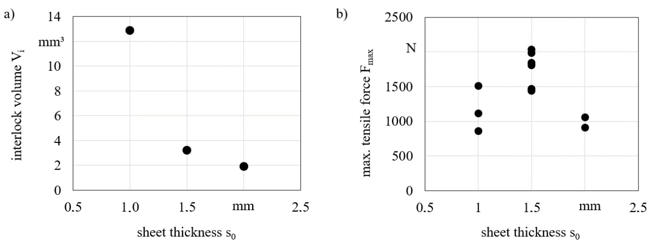
Fig. 10. Influence of sheet thickness s0 (EC = 1250 J, d = 3 mm); a) interlock volume Vi, b) maximum tensile force Fmax.
Joining tests without preparation of the tubes end were performed with carbon fiber tubes and bamboo sticks. These tests proved the adaptability of the shock waves action. Sheet metals were deformed and pressed into carbon fiber tubes with outer diameter of 30 mm and wall thickness of 2 mm without failure of the tubes. Furthermore, without any modifications of the die, the sheet metal formed and adapted smoothly to a bamboo sticks geometry - outer diameter around 26 mm - as shown in Fig. 11. However, bamboo sticks tended to break and need to be supported in further tests. In both cases the achieved strength of the joints was very low as an interlock geometry wasn’t present and the mandrel geometry was completely changed. Hence, further investigations are required.
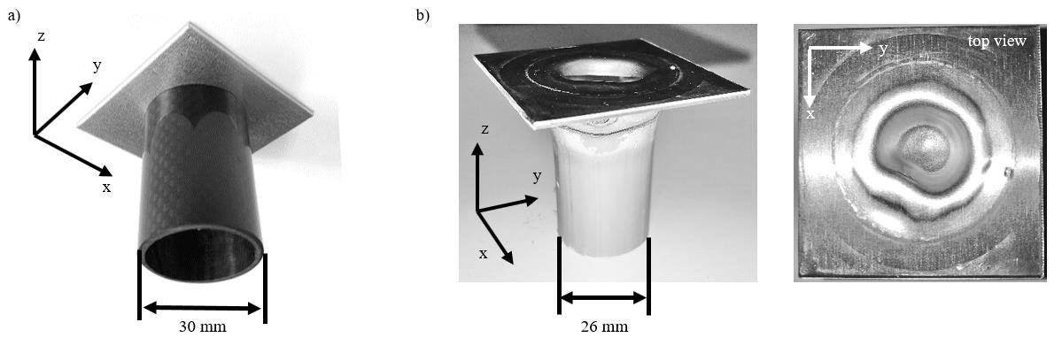
Fig. 11. Joining results (frictional); a) aluminum (1050) sheet to carbon fiber tube, b) aluminum (1050) sheet to bamboo stick.
4. Summary
A novel technology for joining sheets with tubes was introduced that based on electrohydraulic forming. A variation of parameters was researched for joining of aluminum (EN AW-1050) sheets to aluminum alloy (EN AW-6060) tubes. Joints were reached with tensile forces of Fmax ≈ 2 kN.
Following conclusions could be drawn:
-
Shock waves enable a contactless and adaptable transfer of forming energy to the sheet metals to be joined with tubes.
-
Material flow filling the interlock volume of joint was influenced by tube inner edge, mandrel distance and resulting process kinematics. Besides the influence of edge geometry, the mandrel geometry is of special interest for the following investigations
-
Increasing the supplied loading energy Ec, the interlock volume Vi increased as well as the tensile strength. However, using higher loading energies led to an increase of mandrel wear hence new mandrel materials and geometries need to be investigated.
-
Increasing the mandrel distance d, the interlock volume Vi increased and consequently the tensile strength of the joint Fmax. However, the result of this improvement was a stronger local thinning of the sheet metal.
-
Joining of sheets of different thickness with tubes was enabled. However, the thickness influenced the failing behavior from bending to shearing.
-
The electric resistance of the aluminum joints was very low (< 0.08 Ω) thus indicating a good linkage.
-
The forming concept adapted to changing geometry of joining partners and allowed wide tolerances without the need of changing the tools.
Following work will be focusing on modifying the joint to enable as well a linkage of sheets with tubes without a special interlock geometry. Here, especially the knowledge gained regarding the material flow can be used. The aim will be to control the material flow by adjusting the mandrel geometry and the outer annular gap between tube and die in order to achieve a further increase in the local sheet thickness. In this way, the sheet can be locked with the tube without undercutting.
