1 Introduction
Electromagnetic forming is based on the contactless application of force to the workpiece by electromagnetic field forces. The field forces, or Lorentz forces, represent the reaction to the electromagnetic field of the tool coil and the induced current flow within the workpiece. The electromagnetic forces can be used for forming [1], cutting [2] and embossing [3] operations for different workpieces. Regarding sheet metal forming operations, a distinction can be made between the processing of thick and thin sheet metal [4]. The criterion that defines thick and thin is the effective range of the electromagnetic field. If this range corresponds to or exceeds the workpiece thickness, a thin sheet metal forming process is present. In contrast, with thick sheet metal the electromagnetic field only acts in a partial volume of the sheet. The process changes according to the effective volume. In the case of thin sheet metal, the coupled electric current flows in the entire workpiece volume and the Lorentz forces acts as a body force. Based on the short duration of the electromagnetic field, the process can also be divided into two phases. The first phase of action represents the action of eddy currents flow and electromagnetic forces. The second phase is characterized by the action of inertial forces, whereby no further energy is supplied to the workpiece [5].
High current densities [6] and strain rates [7] are induced in the workpiece via the two phases of electromagnetic forming. In consequence, the material behavior is differently modified in the phases by a temperature rise generated by the electric current and by the high strain rates during impacting. Studies deal with the influence of electromagnetic forming on the forming limit curve and the yield stress during forming. With regard to the forming limit curve, Golovashchenko et al. [8] showed that electromagnetic forming allows higher forming limit. The method considers both free forming and forming into a die, and differences between the types of forming were found in terms of the forming limit. It is also shown that the geometry of the die has an influence on the result. Influences on formability were attributed to the high strain rates and high kinetic energy impact. Taebi et al. [9] showed in connection with the combined quasi-static forming and electromagnetic forming an influence on the forming limit curve, whereby the influence is attributed to the high strain rate. In relation to the influence of electromagnetic forming on the yield stress, Chu et al. [10] experimentally showed an increase in yield stress due to electromagnetic forming with flight phase on conical dies. This increase was again attributed to the increased strain rate and impact velocity on the die. In connection with the consideration of the strain rate, Pysk et al. [11] showed the influence of the strain rate and the stress state on the plastic material behavior by using electromagnetic forces in modified tensile testing. The increase of the yield stress and the forming limits by an increase of the strain rate could be proven, whereby in contrast to the quasi-static load, a dependence on the stress state was determined. Based on the performance characteristics of electromagnetically formed components, Bach et al. [12] were able to determine a grain refinement by electromagnetic forming. Regarding material properties, Ma et al. [13] could prove that electromagnetically formed specimens showed lower hardness values compared to formed specimens from a Split Hopkinson test with the same strain rates. In addition, when analyzing and comparing fracture surfaces from electromagnetic ring expansion, Split Hopkinson tests and quasi-static forming, an improved plasticity could be demonstrated by electromagnetic forming.
Based on the preliminary work, the behavior regarding the plastic material properties during electromagnetic forming can be described. However, most methods for the determination of the material properties are based on process variants with flight phases [10] or high workpiece deformation [8], so that the inertial forces contribute significantly to the forming process, or there is a decoupling from the electromagnetic process (modified tensile test [9], combined electromagnetic forming [11]), so that process-related effects as shown by Ma et al. [13] cannot be taken into account. In the special case of forming thin sheets, due to the acting of eddy current in the complete volume with following Lorentz forces, an increase of the influences can be expected. These influences are expected to appear within the whole post-oscillation of pulsed magnetic field [14]. Especially in electromagnetic embossing of microstructures in thin sheet metal, the total strain is small and due to the absence of a flying phase the electromagnetic field is still acting during forming. Therefore, the electromagnetic forming of thin sheet metal takes place during acting of eddy currents. Hence, the effect of the electromagnetic field overlays the forming process stronger. The method for in-process determining plastic material properties presented in the following is intended to show the process-individual influences of electromagnetic forming of thin sheets. Therefore, the final state of the forming process in terms of strain is used and presented in relation to the process cause. The process force is described by the simulated impulse, which is validated by measurement, related to formed geometry. The method is applied for die materials and varying sheet thickness values. Due to this a model for the in-process plastic material behavior during electromagnetic forming was introduced.
2 Experimental Setup
The plastic material properties were determined by the maximum mechanical stress and strain values of aluminum (AA1050A, Al99.5) workpieces that were formed in 6 mm groove dies (see Fig. 1. a). Sheet metal thickness of 200 µm and 100 µm were used with areas of 50 x 50 mm². As die material, cold work tool steel (AISI O2, 90MnCrV8) and aluminum (AA2007, AlCuMgPb) were used. A single conductor with a cross section of 5 x 5 mm² (see Fig 1. b) made from copper (CW004A, E-Cu57) was used as tool coil, which produced an almost uniform force distribution along the coil geometry in the Y-direction. Thus, a description in the X-Z plane can be made under neglecting of edge effects. A variation of the strain was realized by forming with different amounts of charge energy, which resulted in a superposition of the rise in strain with rise of current density and strain rate. The experiments were carried out with charge energy values of EC = 200 J, 800 J and 1800 J in the pulse forming unit. The pulse forming unit consisted of a capacitor bank with 8 capacitors, which was switched by a single ignitron (National Electronics NL508/NL508A). In combination with the tool coil, the discharge frequency was approximately f ~ 14.5 kHz .
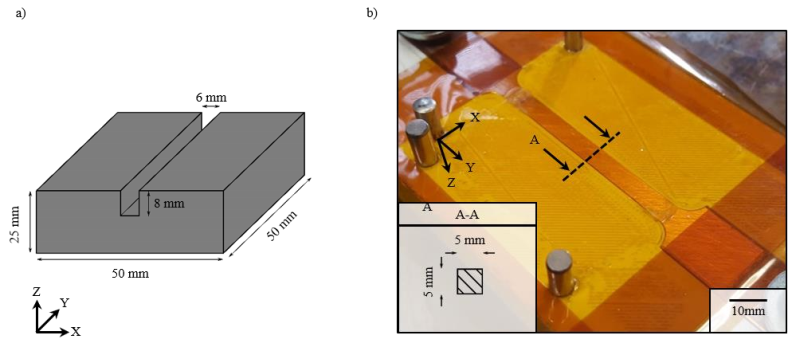 Fig. 1. Experimental setup with (a) die geometry and (b) tool coil.
The strain was expressed by the change of the characteristic surface length L0 (see. Fig. 2). This calculation assumes a constant sheet thickness distribution along the forming zone. The sheet geometry was determined by measuring the formed height hb with a digital microscope (Leica DVM6) in the middle section A-A as shown in Fig. 2. Each experiment was repeated 3 times.
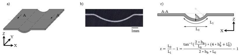 Fig. 2. Determination of the strain (a) resulting specimen geometry (b) embedded middle section cut (c) determination of strain in the middle section.
The mechanical stress was determined by simulating the force during the electromagnetic forming. This simulation was validated by force measurements. The electromagnetic finite element simulation model was implemented in ANSYS Maxwell 2D 19.1.0, whereby the description took place in the X-Z plane (see Fig. 3 a). The model included the tool coil, the workpiece and the die bounded, by the region of simulation. Die and workpiece were modelled according to the groove width – as described in Fig. 1 - and the sheet thickness values. The capacitor discharge was described by a decaying sinusoidal current oscillation (see Fig. 3 b) corresponding to the charge voltage of the capacitor bank. The discharge frequency, damping and the amplitude of the coil current I(t) were based on the pulse forming equipment used in the experiments.
The impulse JR of the workpiece was defined as the output of the simulation. The determination of the impulse was carried out over 500 µs simulation time by integration of the Z-component of the electromagnetic force density ft and was referred to the formed specimen volume see equation (1).

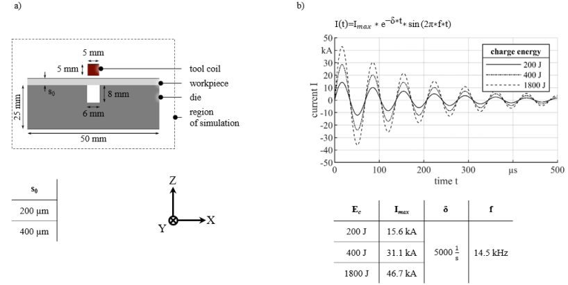 Fig. 3. Electromagnetic simulation model (a) geometry (b) tool coil current for different charge energy.
To validate the simulation, the process force Fm,z was measured during electromagnetic forming by a strain gauge, which was mounted directly into the force flux of the process (see Fig 4 a). For safety reasons, an additional polyamide distance element was placed between the sensor and the tool coil to reduce electromagnetic coupling and field shaping by the measurement device. Additionally, the strain measurement was not analyzed during discharging due to the high electric tool coil currents I that are still present in the unshielded sensor. Therefore, the mechanical vibrations of the system induced by the process force were considered. For this purpose, the 50 kHz lowpass filtered process force Fm,z after the coil current flow (see Fig. 4 b). was integrated over 1 ms and used as a measured impulse characteristic value JC (2).

The force measurements were carried out with charge energy values of EC = 200 J, 800 J and 1800 J with nine repetitions each. Sheet metals with a thickness of 200 µm were formed with flat dies without a groove. To compare experiment and simulation beyond that, the total impulse JS,T over 500 µs for the workpiece and die like in the experiment was determined by equation (3).

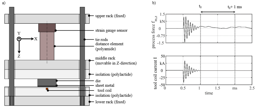 Fig. 4. Setup during force measurement (a) setup (b) measured force and tool coil signal.
3 Results
3.1 Validation of the Impulse Simulation
To validate the simulation, the measured impulse characteristic value JC in Fig. 5 is compared with the simulated total impulse JS,T of the workpiece-die system. Based on the comparison, it can be concluded that both variables correlate in the considered charge energy EC range with each other. The differences in the progress may be due to the missing consideration of change of discharge frequency and efficiency during the discharge when modelling the tool coil current in the simulation. The differences in the effects of die materials in the electromagnetic forming of thin sheet metal have already been described by Beckschwarte et al.[15]. The total impulse was higher when an aluminum die was used in comparison with a cold work steel die as shown in Fig. 5.
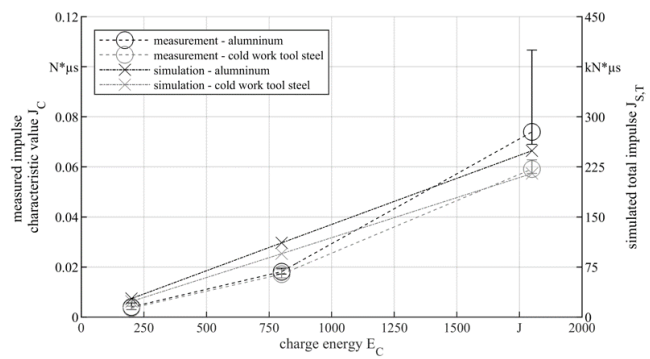 Fig. 5. Comparison of the measured impulse characteristic value JC and the simulated total impulse JS,T for different die materials.
3.2 Determination of Plastic Material Properties
Fig. 6 shows the fundamental dependency of strain and related impulse. By increasing the related impulse by increasing the charge energy, more effect in terms of workpiece strain was achieved. To interpret the results, it should be noted that a variation of the charge energy went along with change in current density and strain rate. So far, the method can therefore only provide a relative comparison of changing conditions. With a cold work steel die, the process limit was reached in the form of cutting the workpiece at the die edges with a charge energy of 1800 J (see Fig. 6). In comparison with the application of an aluminum die, the higher related impulse caused higher workpiece strain. The die material changed both the process effect in terms of stress and strain and the behavior of the workpiece material in terms of the stress-strain curve development. Thus, it is shown that the related impulse requirement for forming with an aluminum die is lower, and the flow conditions are thus favorable. Possible explanations are the changes in current density and in consequence temperature in the workpiece. Furthermore, the steel die evoke failure within the method, which did not occur with aluminum dies. The cutting edges differ in the cutting-edge radius, whereby a radius of ~20 µm was determined for the aluminum die. In comparison the cutting edge of the steel-based die is varying along the cutting edge between ~10 and ~20 µm. Corresponding differences in fracture appearance can therefore be attributed to these differences. Regarding the plastic material properties, an increase in the forming limit or an impact on the fracture mechanism can be concluded. These changes in the fracture mechanism prescribed by Kautz in relation to die geometry and force distribution for electromagnetic tube forming [16]. Thus, the fracture mechanism must be investigated more closely regarding the influence of the die material in terms of influences from cutting edge of the die and electromagnetic and mechanical properties.
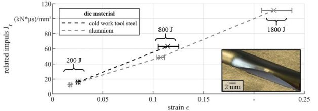 Fig. 6. Comparison of the results of electromagnetic formed 200 µm thick sheet metal (AA1050A, Al99.5) with different die material.
The variation of the sheet thickness did show similar determined plastic material properties (see Fig. 7). Differences by the variation of the sheet thickness were expected regarding flow restriction based on the ratio of sheet thickness to grain size [17]. A change in the plastic material properties was also expected due to rise in current density and the resulting temperature. Furthermore, the expected increase in the strain rate, due to the decrease in the mass of the workpiece, showed no significant impact. In connection with the superposition with the reduced sheet thickness, which is accompanied by a reduced electromagnetic coupling, no statement could be confirmed regarding the influence on the plastic material properties.
Regarding the specimen failure, different effects occurred. During the forming of 100 µm with 1800 J a deviation in the behavior of the workpiece was determined. For one sample, a deviation in the sample geometry was determined in connection with the circular segment shape (see Fig. 7). This deviation might be explained by the influence of the force and velocity distribution [18] and the influence of the air resistance [19]. Further samples, however, showed failure like Fig. 6, whereby in Fig. 7. a decrease in the sheet thickness in the die-contact area can already be seen.
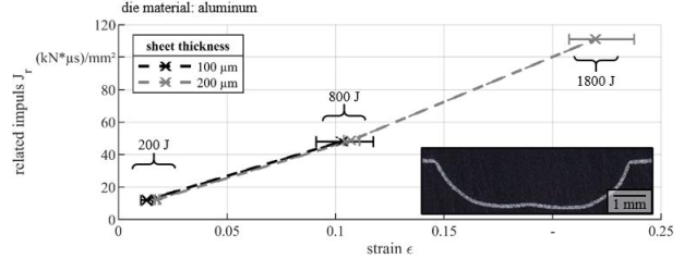 Fig. 7. Comparison of the results of electromagnetic formed 200 µm and 100 µm thick sheet metal (AA1050A, Al99.5) with an aluminum die.
4 Conclusion
A method was proposed the possibility to investigate the material behavior during the electromagnetic forming of thin sheet metal. To vary the forming conditions, different die materials were investigated, which showed an influence in the resulting plastic material behavior. Hence, it was shown that the modelling of electromagnetic forming of thin sheet metal must include the die and the following changes in the plastic material behavior. The following results were achieved by applying the method:
· The used simulated related impulse correlated with the measured forced oscillation based on the process forces during electromagnetic forming
· The presented method of strain curve determination could be used to detect differences in plastic material behavior during electromagnetic forming
· The methods enable by a relative comparison the in-process determination of the plastic material behavior
· The plastic properties of the workpiece during electromagnetic forming of thin sheet metal could be influenced by the die material
· Usage of aluminum in contrast to cold work tool steel-based dies resulted in lower impulses but also in lower needed related impulse during electromagnetic forming
· A variation of the sheet metal thickness showed no significant impact on the determinate plastic material properties, whereby the conditions during forming were changed
For high charge energy the electromagnetic forming of 100 µm thick aluminum sheet metal the geometry is superimposed, resulting in a noncircular segment shape forming result. This geometrical deviation must be attributed to a cause in future work. Furthermore, influences on the plastic material properties during electromagnetic forming should be varied. Examples can be the provision of a decoupling from eddy current flow by a specific flight phase. Still, a further variation of the sheet thickness as well as the die geometry is pending.
Acknowledgements
The authors gratefully acknowledge the support by the German Research Foundation DFG for the project “Electromagnetic embossing of optical microstructures” with the grant number 395821503 (KU1389/17-1).
