1 Introduction
In recent years, manufacturing processes have to meet a trend towards smaller batch sizes and individual products. Already existing approaches that help to support this trend are rapid prototyping processes like 3D printing that offer a high degree of flexibility due to a rapid provision of the product. Fused deposition modelling (FDM) of polylactide (PLA), as an example for 3D printing processes, is advantageous due to its low-cost while sufficient printing quality. However, existing conventional metal forming processes are limited in the ability to follow this trend due to the dependence on rigid tools that have to withstand high static loads. Here, the punch and the die have to be produced very precisely out of hardened steel, which is associated with high costs and time expenditure. As a result, the typical forming processes like deep drawing or stretch forming can only be used efficiently for larger product quantities. In addition, the adaptability of the product range is relatively low, due to the long product development process. To accelerate the product development a wide range of previous work was focusing on faster tool provision, which spread from modular [1] and reconfigurable [2,3] tools to completely new approaches of tool production [4] like stereolithography processes [5]. Langstädtler et al. showed that the combination of impulse forming and flexible tooling offers three different fields of flexibility for a rapid manufacturing, which are categorized into the aspects of die material, tool provision and process design [6]. The idea of rapid tooling for forming, embossing and cutting processes arose with a strategy that combines impulse forming processes like electromagnetic forming (EMF) or electrohydraulic forming (EHF) - where the die is loaded and unloaded very quickly by an adaptable force action that replaces the punch - with unconventional die materials and new tooling concepts. Furthermore, to increase the flexibility of the production and to make sheet metal forming more suitable for smaller quantities, impulse forming can be used not only for tooling but also for production process.
The electrohydraulic forming process was first researched by Yutkin [7]. In this impulse forming process, a wire within a fluid is vaporized using a high energy pulse which creates a shock wave within the fluid transmitting the force action to the sheet metal. Besides the use of unconventional die materials like plastic, that were already introduced to forming processes [8], dies for impulse forming do not need a static rigidity, but an impulse rigidity [9]. This process property enables very fast die production by utilizing fused deposition modelling with polylactide. One disadvantage of these dies is their live expectancy which is only a few parts down to a single forming operation.
To investigate rapid tooling with enhanced 3D-printed polylactide dies, two new methods were introduced in this research. On the one hand side, the dies were armored with metal sheets. These sheets were expected to generate a better distribution of the forming forces on the die. To further increase the life time of rapid tooled dies a new process chain was tested. Therefore, copper sheets were formed using the 3D-printed polylactide dies. These sheets were then used as sink electrodes for electric discharge machining to produce complex steel dies with improved live expectancy and form stability.
2 Materials and Methods
For the experiments, an electrohydraulic forming set-up was used, Fig. 1. This set-up consisted of an electric pulse generator and a modular forming unit. The electric pulse generator included a capacitor bank with a maximum loading voltage of U0 = 6 kV and a capacity of C = 100 μF resulting in a maximum loading energy of EC = 1800 J. The capacitor bank was loaded by a high voltage energy source. The base of the set-up was the pressure chamber with two electrodes which were electrically insulated towards the chamber. A thin wire (aluminum Al99.5 wire 0.3 mm in diameter) was mounted between the electrodes. On top of the chamber a faceplate was placed, which localized the forming force to a specific location, and the pressure plate. The pressure plate clamped the sheet metal with a thickness s0 and the die sealed the connection between the faceplate and the sheet metal. By short circuiting the loaded capacitor bank over the wire, the wire was vaporized and causes shock waves that form the sheet metal into the die.
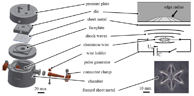
Fig. 1. Experimental set-up for electrohydraulic sheet metal forming
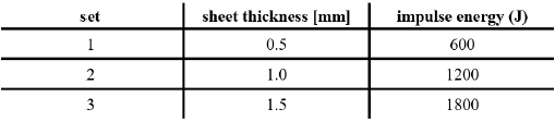
The formed aluminum Al99.5 (EN AW-1050A; 3.0255) sheet metals were measured after forming using a Leica DVM6/M digital microscope as well as a Keyence 3D scanning microscope VK-X210. With polylactide and armored dies, forming experiments were performed with a five-pointed star geometry with sharp corners and a central plateau as shown in Fig. 1. The impulse load on the dies was varied with constant ratio of energy per sheet thickness forming aluminum sheet metal as given in Tab. 1.
Table 1. Star forming experiments nomenclature
The dies were analyzed after the first and the third forming operation. Beneath the replication capability of the surface structure, the molding accuracy was determined (formfilling of edge radius of the star points). For die manufacturing, three variants were tested, Fig. 2. As variant 1, the 3D-printed PLA dies were directly applied. As variant 2, the PLA dies were additionally armored. For this purpose, a 0.5 mm thick aluminum sheet was accelerated into the dies by EHF and remained there as a part of the die without any additional bonding. Due to this additional layer, the core geometry needed to be modified. As variant 3, copper (EN CW004A, 2.0065) sheets with 0.5 mm thickness were formed by EHF with PLA dies. Afterwards, these sheets were used as electrodes in an electrical discharge machining (EDM) process to produce a steel duplicate of the initial PLA die. The aimed advantage of this steel (EN 10025-2: 2004, 1.0570) dies was a significantly longer tool life and the ability to form thicker sheets either by electrohydraulic forming or conventional punching.
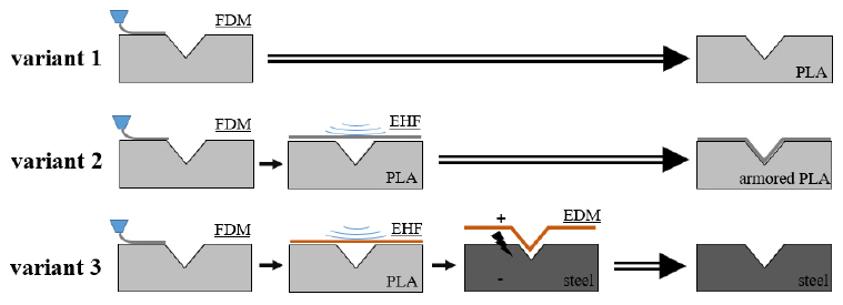
Fig. 2. Rapid tooling for impulse forming (FDM - fused deposition modelling; EHF - electrohydraulic forming; EDM - electrical discharge machining)
3 Results
3.1 Variant 1 - Polylactide Dies
Forming with polylactide dies (variant 1) showed form-filling of complex star-geometry for all sets of energy and sheet thickness, Fig. 3. However, due to the possibility of different effects like an insufficient forming energy, the sheet metal kinematic, rebounding of the sheet metal or air cushions between sheet and die, a complete form-filling of the edge radius of the star geometry was not achieved in all cases. Nevertheless, a replication of the fine printing structure was possible.
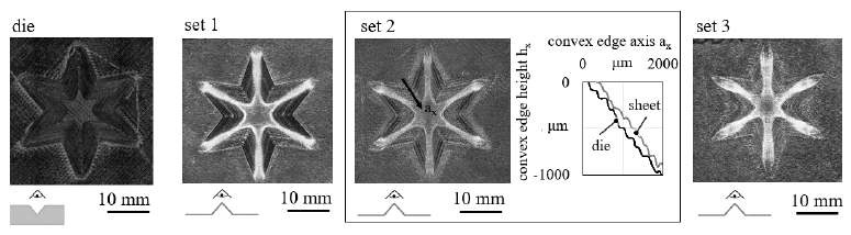
Fig. 3. Polylactide die and sheet metal forming result (sheet metal convex die-side), pictograms show the deception of view on die or sheet
Regarding the experimental results, three different curve sections of forming behavior can be observed in the height difference curve, Fig. 4b. The height difference increased from the outer corner with ax = 0 μm to the center with ax = 6000 μm over all curve sections. The width of the first section - where the height difference was low and the micro structure replication was high - changed for all sets. For set 1, the first section was observed from ax = 0 μm to ax ≈ 3500 μm. For set 2 first section was observed from ax = 0 μm to ax ≈ 2500 μm and for set 3 the first section was observed from ax = 0 μm to ax ≈ 2000 μm. The second (transition) section was located between ax = 2000 μm to ax = 4000 μm with an increase of the height difference ending at the flat bottom of the die. The width of this section depended on the first sections width. Besides, here the replicated structure was reduced in accuracy. The maximum height difference resulted in the star center within the flat area (third section) for all sets from ax = 4000 μm to the center with ax = 6000 μm, where the sheet metal impact was expected to be maximum. Here, the height difference increased from set 1 to set 3. The obvious frequency in the graph in Fig. 4b was caused by the printing structure on the sheet metal and the die. Here, a positive value was caused by a small gap between sheet and die, a negative value by exceeding the dies geometry by the sheet metal. With increased impact on die from the outer corner to the center this replicated structure height slightly decreased.
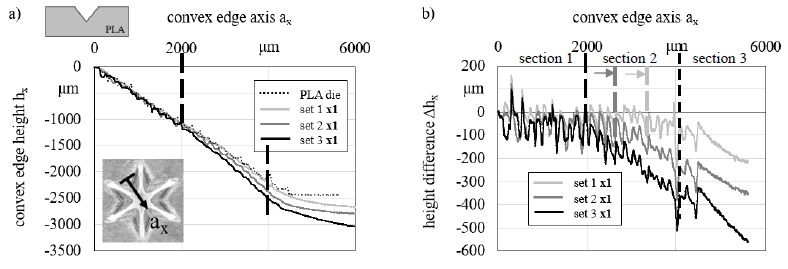
Fig. 4. Formed sheet metal geometry for set 1, 2 and 3 compared to PLA die geometry; a) height profiles, b) difference of formed sheet metal and die geometry
A homogeneous shock wave impulse pressure distribution was expected that accelerated the sheet metal into the star geometry. However, due to the star geometry starting from zero height at the outer corner, the sheet metal directly started to be pressed against the die hence is formed and decelerated. Consequently, in this border area the sheet metal velocity was expected to be low, however the pressure was high enough to form the sheet metal. The further the sheet volume proceeded in the center of the star, an ongoing acceleration by shock waves took place. Here, the reduction of velocity by free forming work is expected to be low. Hence, after an almost free forming of the sheet metal, it hits the die in the center bottom with high kinetic energy. Depending on sheet metal velocity and mass, then, an ongoing rolling of the sheet metal to the side and into the star edges accordingly was expected. Both forming movements of the sheet metal, directly form-filling of the die geometry by shock waves pressure with lower velocity and form-filling by sheet metal inertia with high velocity, are taken into account influencing the force action on the sheet metal. The force action causes, depending on contact conditions with the die and free areas of the sheet metal, different stress and strain conditions that are distributed over the complex geometry during forming. Hence, the forming behavior of the sheet metal the die loading is strongly inhomogeneous.
A further geometric deviation was observed by using the dies several times. With each hit of the sheet metal on the die, the die strained plastically which resulted in increasing height difference, Fig. 5. However, this increase of height difference was located mostly in the third section. This observation underlines the thesis of inertia effects in forming and load on the die.
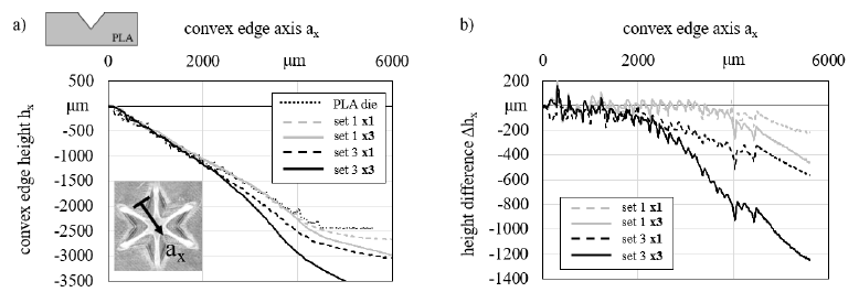
Fig. 5. Forming result development - repetitively applied on polylactide dies - after one and three operations
3.2 Variant 2 - Armored Dies
Rapid tooling by armoring the 3D-printed polylactide dies (variant 2) was enabled due to high plasticity of armoring sheet metal and low spring back. After cladding, no gap between forming die, which was then used as core, and armoring sheet metal was detected. Due to the strain during cladding a strain hardening hence a local increase of strength – in comparison to unformed sheet metal – was expected. The armoring sheet metal functioned as interpolation layer that can be used for smoothing the printing structure of PLA die which resulted in no replication of printing structure on formed sheet metal, Fig. 6.
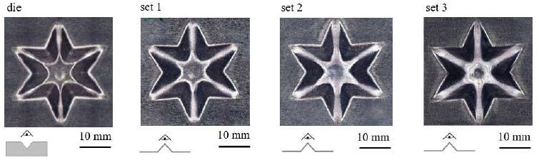
Fig. 6. Armored die and sheet metal forming result (sheet metal convex die-side), pictograms show the deception of view on die or sheet
Interlayering needs to be considered in design of the die core geometry which has an effect on forming and die load in consequence. In forming tests, same areas arose as described before. However, the height difference curve was lower at the flanks in second area than for using dies without armoring, Fig. 7. Geometric deviation was maximum at the center of the star geometry as well.
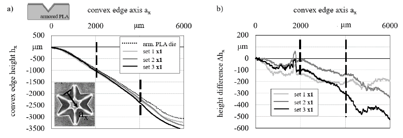
Fig. 7. Formed sheet metal geometry for set 1, 2 and 3 compared to armored die geometry; a) height profiles, b) difference of formed sheet metal and die geometry
By increase of the number of forming operations with the armored die (Fig. 8) geometric deviation increased, however it was lower at the flank than for PLA dies. Thus, the die failed (cracking of armoring sheet in the center) earlier on the flat area 3 in the center for set 3 after two repetitions. Therefore, the graph is missing in the figure. This effect is expected to be caused by two main reasons. First, due to changed die geometry (to consider the sheet thickness in the final geometry), the armoring sheet was already stressed near the failure limit. Second, due to changed die geometry and less energy dissipation according to a smoother die surface, the kinetic energy of the sheet metal hitting the die center was higher than for PLA die.
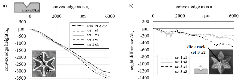
Fig. 8. Forming result development - repetitively applied on armored dies - after one and three operations
3.3 Variant 3 - Steel Dies
Rapid tooling for impulse forming (variant 3) with steel dies was tested by electrohydraulic forming flat copper sheet metal electrodes for electrical discharge machining. In this variant, the geometry was changed. Since the process chain introduced here contrasts with the conventional production of a steel tool by milling, the advantages are to be illustrated by the complexity of the geometry. The T-geometry combined steep flanks with free form features at the bottom of the cavity, which are difficult to mill.
Copper sheets with an initial thickness of 0.5 mm were electro-hydraulically formed with high accuracy using los cost PLA dies. Afterwards, they were used as electrodes in EDM to transfer the die geometry to the steel blank, Fig. 9. The EDM process was performed five times with new electrodes due to electrodes burn-off. This was mainly made possible by the fact of low scattering of formed sheet metals geometry, which allowed to continue the erosion process with a new sheet metal. Thus, the principal usability of the tooling chain was proven. With the new steel die aluminum sheet metals with a thickness of up to 3 mm could be formed. Furthermore, as a die made of conventional steel results from this tooling chain, the die can as well be used for conventional quasistatic forming processes.

Fig. 9. Rapid tooling chain for steel dies and formed sheet metal (s0 = 3 mm), pictograms show the deception of view on die or sheet
4 Summary
Rapid tooling for impulse forming was introduced in three different variants each with its specific advantages, all including 3D-printing as part of the die manufacturing chain with the result of lowering costs. The first variant was realized by 3D-printing of polylactide dies. Here, aluminum sheets with a thickness up to 1.5 mm were successfully formed, even several times with the same dies. Furthermore, even fine FDM features of PLA dies were replicated by electrohydraulic forming.
Armored dies, which were introduced as second variant, were exemplarily tested for forming. Due to layering of the sheet metal on the core, the die surface was smoothened. The stiffness of the flanks of the forming dies was increased. Change in core geometry led to an increase of load due to kinetic energy which has to be considered in design.
Considering quality and costs for first and second variant, by first variant sufficient forming quality was reachable with lowest costs. However, for increased loads and a smoothening of surface the second variant showed better forming quality with little increase of costs in comparison to first variant.
The third variant was shown by a testing T-geometry. Copper sheets were electro-hydraulically formed on PLA die with replication of fine features and then successfully used as sinking electrodes for EDM process in conventional steel. Here, conventional electrode manufacturing by turning or milling was replaced by impulse forming with low-cost dies which enables to reduce manufacturing time and costs. Even though, in comparison to first and second variant the costs were increased by variant three, with this die manufacturing chain, complex shaped freeform geometry dies can as well be used for impulse forming thick sheets as well as for conventional quasistatic forming processes.
5 Outlook
Future work will focus on investigating further features and geometric accuracy of the armoring sheet as well as the realization of bonding strategies to modified core materials. Furthermore, besides the coverage of the whole die, a local armoring can be used for die modification. An example for this is the armoring of cutting dies. Here, the change of flat areas of the die, as well the cutting edge is modified. An armoring sheet was cut with a PLA die and afterwards used to increase edge stiffness on PLA cutting die, Fig. 10.
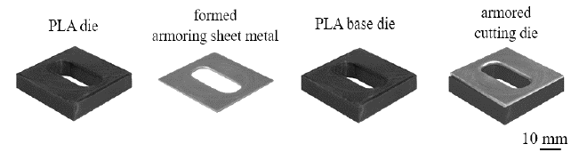
Fig. 10. Armored polylactide cutting die
Acknowledgements
The authors gratefully acknowledge the support by the German Federation of Industrial Research Associations (AiF) for the project „Entwicklung des Elektrohydroumformens zum partiellen und inkrementellen Umformen“ supported by the Federal ministry for Economic Affairs and Energy and the ZIM (Zentrales Innovationsprogramm Mittelstand).
