1 Introduction
Electromagnetic forming (EMF) uses the energy density of pulsed magnetic fields to apply forces to electrically conductive work pieces without mechanical contact and form them at high speed. Depending on the geometry and the arrangement of tool coil and work piece, tubes can be compressed and expanded and sheets can be formed [1]. Harvey and Brower [2] proposed EMF in the 1960s, but excessive expectations and restricted tool life and cycle time, as well as the complex process design have been hindering the breakthrough. However, the increasing use of aluminum in connection with lightweight construction concepts led to a renaissance of the technology combined with increased research activity since the early 2000s [3]. Numerical simulation developments strengthened this trend and provide the basis for virtual tool and process design [4]. Fig. 1 shows a principle sketch of a typical electromagnetic sheet metal forming process.
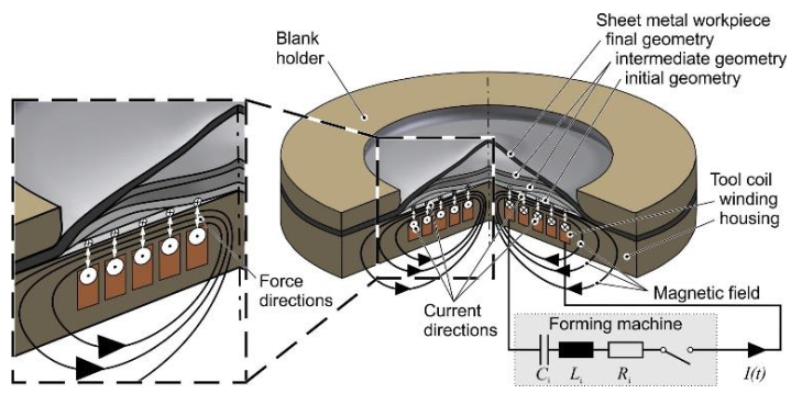 Fig. 1: Process principle of electromagnetic forming [5]
For the process, a capacitor battery is charged to a defined voltage and then discharged via the so-called tool coil (inductor) so that a damped sinusoidal current flows, which causes a transient magnetic field. This induces eddy currents in the electrically conductive work piece in the opposite direction to the inductor current.
According to [6], this eddy current is concentrated only on the surface of the work piece due to the so-called skin effect. This effect only occurs at currents with high frequencies. The reason for this is that small eddy currents also occur in the conductor, which flow to the interior of the conductor in the opposite direction to the general direction of the current. Thus, the current is displaced from the center and flows primarily on the outside of the conductor. The penetration depth, also called skin depth, depends on both the conductivity of the work piece and the frequency of the current.
Interactions between magnetic field and current cause Lorentz forces, which can be mathematically transformed into a so-called magnetic pressure. As a result, areas of the work piece are plastically formed when the yield stress is reached. The typical EMF pulse duration is about 15 to 100 µs. During this time, the magnetic pressure increases up to several hundred MPa and then decreases [7]. The work piece is accelerated to speeds of up to several hundred m/s and achieves strain rates in the order of 103 to 104 s-1 [3]. The high strain rates lead to significantly increased forming capacity for many materials [8], which can be used in particular for forming complex geometric details. Together with the non-contact and particularly surface-protective application of force and the possibility of integrating cutting or joining operations between different metallic and non-metallic materials into the process, this represents the most important technological advantage of EMF compared to conventional methods. Further advantages are reduced springback [9], short process times and high productivity [10].
However, due to the high eddy currents heating occurs in the work piece. In general, due to the skin effect, this has no significant influence, because the heating is concentrated on the surface of the work piece. Thereby the thickness helps to compensate the temperature, but with decreasing thickness, the influence is increasing. Furthermore, if the sheet thickness is lower than the skin depth, the magnetic field penetrates the work piece, which in turn needs higher magnetic field strengths for its deformation. Especially for materials with low electrical conductivity, such as stainless steel or titanium, these effects have a higher impact.
To overcome these drawbacks it might be useful to include an additional transmission element with high electrical conductivity, a so called driver, to support the electromagnetic forming process. Typically, these drivers have a thickness of 0.5 to 1.5 mm and can only be used once, because they undergo the same deformation like the work piece. Especially for high volume production, this is not economic. Due to this, it is better to increase the thickness and thus the stiffness of the transmission element. For a better distinction, this stiff, reusable transmission element will be called force initiator in the following sections.
2 Electromagnetically driven tool
With an electromagnetically accelerated tool, the coil no longer represents an element of the shaping components. Instead, it acts as the drive of the tooling system, comparable to an electric motor of a spindle press. Nevertheless, it still has to meet the same requirements as for direct electromagnetic forming. For this reason, a comprehensive numerically assisted design is required here as well. One example, how this can be done for a compression coil with field shaper is shown in [11].
Depending on the application, the force initiator can already be fixed to a part of the shaping tool, e.g. to a punch for adiabatic blanking [12]. Alternatively, it can also act as a kind of plunger to accelerate or compress a working media. In the case presented here, the aim is to form micro flow channels in a thin foil (0.1 mm) of stainless steel 1.4404. The channel cross-sections are designed in such way that they resemble the usual geometry of a channel of a bipolar plate and follow a meandering path over the active surface (Fig. 2). The channels also have holes with a diameter of 0.3 mm, which are used to evacuate the air located inside the die.
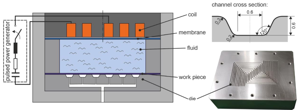 Fig. 2: Left: Concept for Electromagnetic driven tool with fluid. Right: Corresponding die and channel cross section.
In order to ensure the greatest possible flexibility and to avoid unnecessary alignment effort, a counter die was not used for the investigation. Instead, the force initiator is used as membrane, which seals off a basin filled with fluid. Here, the fluid is a highly diluted lubricant, which is also used in conventional drilling machines. The work piece is fixed to the die by the vacuum, which evacuates the active area.
3 Proof of concept
At the beginning, the aim was to prove that the concept works in practice. For this purpose, due to production delays, an existing spiral coil was first used. For the proof of concept, the membrane consists of an EN AW 7075 sheet with a thickness of 2 mm. As a result, the membrane has a low Young's modulus combined with higher tensile strength. Due to the low Young's modulus, the membrane can achieve a higher elastic deformation and a larger elastic displacement, at the same yield point. The high tensile strength ensures that plastic deformation of the membrane does not lead to a crack too quickly. Otherwise, leaking fluid could lead to a short circuit and thus to the destruction of the coil. For the experiments, an additional flexible layer was included around the die to prevent the fluid from flooding the channels before the forming process. The experiments were executed at different capacitor charging energies in the range of 5 to 15 kJ. Fig. 3 exemplarily shows the result for 15 kJ and measured cross sections for 12.5 kJ and 15 kJ.
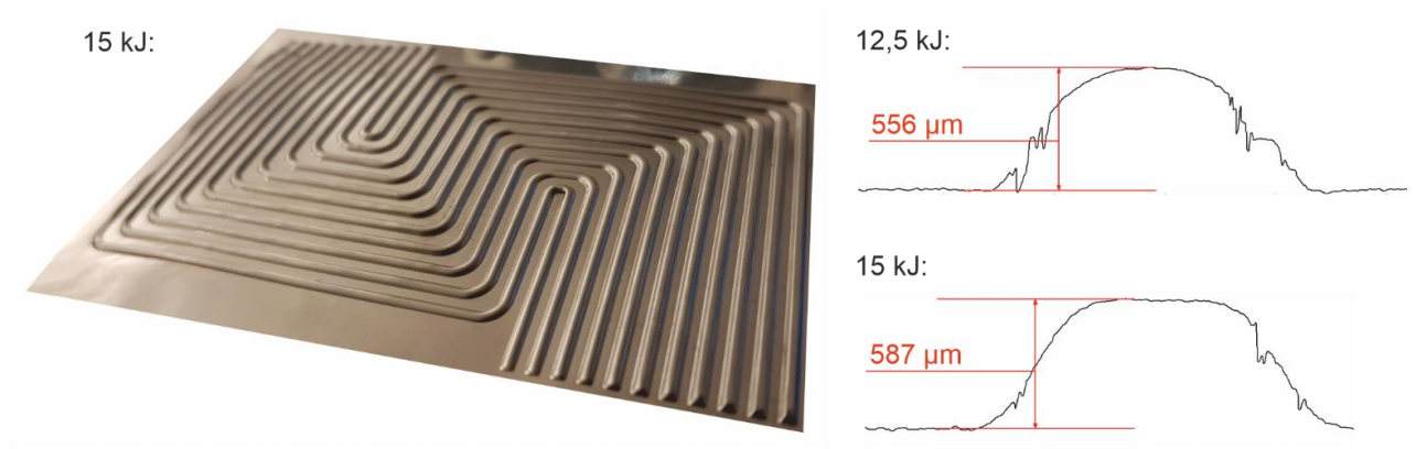 Fig. 3: Left: Experimental result for 15 kJ. Right: measured cross sections for 12.5 kJ and 15 kJ (exemplarily)
The measurements were done with the optical 3D measurement system MikroCAD in the sub-micrometer range. Thereby, a defined structured light is projected onto the component, which is then warped according to the geometry. The resulting light image can then be taken by a camera and converted into exact 3D data. The resolution of the system can be set to an accuracy of up to 0.1 µm.
Fig. 3 clearly shows that it is possible to form the selected channel structure with the use of the electromagnetically accelerated tool and a fluid. Nevertheless, the experiments also show that a homogeneous deformation over the work piece geometry does not occur. The reason for this is that a non-uniform pressure is applied to the membrane with the selected spiral coil. This in turn leads to an asymmetric acceleration of the fluid. It is possible to compensate this effect by increasing the capacitor charging energy accordingly. This is shown in Fig. 3, too. However, it can also be seen that increasing the capacitor charging energy by 20% only results in a 10% increase in the forming depth.
A better solution is to unify the pressure over the complete surface area of the die. On the one hand, this can be achieved by using a coil with a better pressure distribution as e.g., described in [11]. On the other hand, the force initiator can be locally stiffened to achieve a more uniform pressure distribution within the fluid. In the further process of the project, both variants shall be realized, combined and each by itself. However, in order to find the best alternative, the use of numerical methods is mandatory.
4 Numerically assisted process design
The aim of the numerically assisted process design is to find appropriate solutions for the pressure distribution. Therefore, the model of the proof of concept as well as the model for a locally stiffed force initiator and the use of a coil with a symmetrical magnetic field were build. Fig. 4 depicts these models, which where setup in LS-DYNA as 3D multiphysics models considering the electromagnetic, fluid and structural domain. The main difference is the generation of pressure. In the new setup, the force initiator consists of a two solid aluminum plates, which are connected to an elastomer membrane. Thereby one part the outer part is to build up the acceleration system and the inner part is to unify the pressure in the fluid. Furthermore, a cylindrical inductor is used together with a field shaper [11] in order to generate the magnetic force on the outer force initiator. The second setup features the spiral coil of the proof of concept, which directly acts on the aluminum membrane as described above.
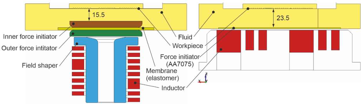 Fig. 4: Cross section of the numerically investigated 3D models. Left: Flyer setup. Right: Direct membrane setup
In both models the Arbitrary-Lagrangian-Eulerian method (ALE) was used to model the fluid characteristic and specific LS-DYNA keywords (*CONSTRAINED_ LAGRANGE_IN_SOLID) where applied to incorporate the Fluid-structure interaction of the force initiator, membrane, housing and work piece with the water. A so-called immersed method was applied, which means, the structural parts are completely surrounded by the fluid and the Eulerian movement of the fluid transfers penalty forces to the structure and the Lagrangian movement of the shells or solids forces vice versa to the fluid. Displacement boundary conditions were set at the fluid boundaries and membranes. As material model of the water, a *MAT_NULL material (ρ = 998 kg/m3, dynamic viscosity μ = 1.002e-3 Pa.s) with a Murnaghan equation of state (also known as Tait equation) was used (γ = cp/cv = 7.0, K0/γ = 3.214e8 Pa, v0 = 0.0). The structural material of the work piece and membrane (in the direct membrane setup) was described by a *MAT24 material with appropriate flow curves and the elastomer membrane (Fibroelast 65 Shore A) as *MAT_OGDEN_RUBBER (ρ = 1240 kg/m3, ν = 0.49, Ogden parameters μ1 = 0.2086e4, μ2 = 7.0809e6, α1 = 5.0781, α2 = 0.7097). To complete the material definition, the electromagnetic material is defined by the electrical conductivity to be σCu = 44 MS (inductor, field shaper) and σAl = 26 MS (force initiator). Boundary conditions for the electromagnetic setup are a RLC circuit (R = 5 mΩ, L = 100 nH, C = 330 µF) with a charging voltage of U0 = 9.53 kV (corresponds to 15 kJ), which is connected to the coils. Fig. 5 depicts some of the results.
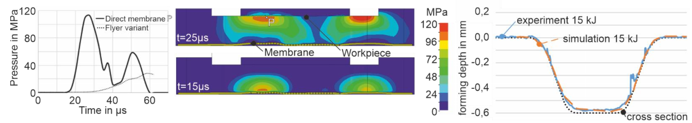 Fig. 5: Simulation results. Left: Pressure curve at point P for both models. Center: Pressure field distribution at two time steps of the direct membrane setup. Right: Numerical forming result of direct membrane compared with experiment and channel cross section.
In particular, for the direct variant, the simulation verifies the highly inhomogeneous pressure distribution, which significantly varies over time and space due to the wave propagation in the fluid (pressure pulse). Furthermore, this variant features much higher pressures (115 MPa) on the work piece, compared to the flyer setup (max. 30 MPa). In the latter one, a real wave propagation of the pressure pulse cannot be observed; it is rather a (significantly slower) varying pressure field distribution. As shown in figure Fig. 5 right, the numerical deformation of the work piece is in good accordance with the experiment. Interesting issues could be numerically reproduced, such as incomplete forming of some areas due to the inhomogeneous pressure distribution. Because of the extremely fine shell mesh of the work piece (mesh size about 0.13 mm), the fine ALE solid mesh (mesh size min. about 0.5 mm) and the main cost driver – the BEM method in LS-DYNAs electromagnetic solver, the simulation costs are relatively high (up to 48 h at 24 processors).
5 Conclusion
Considering the results, it is obvious that it is possible to form micro flow channels in very thin sheets by using an electromagnetically driven tool and a fluid. It could be shown that special attention has to be paid to the efficiency of the pressure application to accelerate the force initiator and the subsequent distribution of the pressure through the fluid. Here, the numerical methods shown can be used to provide optimal process parameters.
However, it should be taken into account that due to the fine meshing and the coupled simulation, very high computing times have to be expected. Here it is advisable to find methods to speed up these calculations. For example, a coarser mesh could first be used to determine the pressure pulse of the force initiator in order to find the appropriate tool parameters. Afterwards, finer meshing can be used to determine the forming result for different work piece geometries using the calculated acceleration of the force initiator. Another important aspect that should be further investigated is the combination of membrane and force initiator.
It is probable that various membrane properties (such as Shore hardness) have an influence on the acceleration of the force initiator. In addition, the geometry of the inner force initiator can be used to specifically influence pressure waveforms within the fluid. Similarly, the properties of the fluid, especially viscosity, are expected to have a strong influence on the propagation of the pressure shock wave.
Thus, it becomes clear that there are still some aspects of the electromagnetically driven tool with working media to be investigated in the future. Nevertheless, the work done so far has demonstrated that the technology is capable of forming the required geometries. Thus, the spectrum of electromagnetic forming can now be extended to electrically non-conductive or low conductive and very thin materials.
Acknowledgements
These results are co-financed with tax funds based on the budget approved by the members of the Saxon State Parliament and supported as High Performance Centre Smart Production and Materials.
