1 Forming using stamp or PUR matrix
The use of rubber for stamping has significant advantages in that it behaves like liquids when pressed against it. If you put a certain amount of rubber in the cylinder and then apply a force on one side, the force will be evenly distributed over all surfaces with which the rubber contacts. Rubber also exhibits cohesion and resistance to flow which are properties not found in liquids. This plays a very important role when shaping materials. The cohesion of rubber has certain limits and therefore it is necessary to pay attention to this property when designing tools and not to put too high demands on this material. It should also be possible for the rubber to hold its shape. Cracking of the rubber must be prevented, which increases its life considerably. A common feature of all rubber stamping processes is that only one part of the die, i.e. the punch or die, is made of rubber, which significantly reduces the cost of the tools. The rubber cushion is usually attached to the press slider and moves with it. Upon contact with the shaped punch on the bottom plate of the die, the rubber presses the plate around. The usual methods of plastic processes, widely used in large- scale and mass production, are ineffective and irrational in the conditions of small-series and quickly changed production, because the production of structurally complex and expensive devices requires a longer period and the costs incurred are unprofitable. The necessity to quickly implement new types of products requires the use of new technological processes of universal or partially universal equipment under given conditions. In the Guerin process, a rubber cushion is mounted on the press slider, and a shaped punch is placed on the table. This process is one of the oldest and the most widely used in rubber stamping. The process has some disadvantages which make it suitable for stamping relatively shallow light metal objects. In general, stampings deeper than 32 to 38 mm are not used. The most suitable for this method are items that have straight shelves, stretch flanges or grooves (ribs), and are made of flat blanks.
2 Design of the container geometry
The production of heat containers required redesigning and developing the method of their production due to the change in the stiffness of the container and the target working pressures. Manufacturing methods such as waste methods and non-waste methods were analyzed. Due to the potential implementation of this type of solution of containers for phase change materials for aviation, the cheapest solution in the form of a tool for forming heat containers was provided. The waste method was rejected due to the necessity to reduce the mass with the use of wall thickness, i.e. 1 mm for materials such as copper alloys: Cu-DHP, stainless steel: 1.4301, aluminum alloy: PA4.

Fig. 1. Forming die designed in the CAD system.
Forming takes place with the use of a PUR polyurethane elastomer (Fig. 1) on a hydraulic press. This process is characterized by the use of an elastomeric punch and pressure with a steel die. The use of Finite Element Method software has positively verified the possibility of forming a given shape. The Autoform software version forming was used for the computing all processes.
3 Material research
The material strength analysis was also carried out. In order to verify the strength of the tested materials, properly prepared samples were subjected to a tensile test. In order to prepare the samples, they were machined with the tolerance according to PN- EN 22768-1. The material was cut along the rolling direction of the sheet. Samples of three types of materials were tested, i.e.:
a) 1.4301 (X5CrNi18-10) is a chromium-nickel steel resistant to corrosion. It has very good weldability. It has admixtures: C 0,07%; Si 1,0%; Mn 2,0%; P 0,045%; S 0,03%; Cr 17,5-19,5%; Ni 8,0-10,5%; V 0,1%.
b) Cu-DHP (CW024A) is phosphorus deoxygenated copper with high phosphorus content, very plastic, very well weldable and resistant to hydrogen. Its chemical composition is 99,9% Cu and 0,015-0,04 P. Properties in a soft state are: tensile strength of Rm 220-260 MPa, min. yield point of Rp0,2 max. 140 MPa, hardness of 40-65 and ductility A50 of min. 33%.
c) PA4 (aluminum alloy 6082) is a corrosion-resistant aluminium alloy with an average hardness of approx. 90 HB, weldable. It has admixtures: Si 0,7-1,3%, Mg 0,6-1,2%, Mn 0,4-1,0%, Fe max. 0,5%, Cr max 0,25%, Zn max. 0,2%, Ti max 0,1%, Cu max 0,1%, others: max 0,15%.
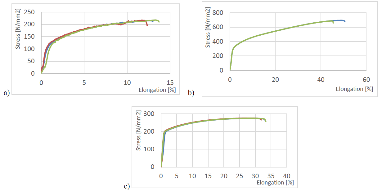
Fig. 2. Stress-elongation diagram for: a) aluminum alloy PA4, b) 1.4301 steel c) Cu-DHP.
4 FEM analysis
The development of the container stamping process technology was preceded by the development of a numerical FEM model of the forming process. This is necessary due to the fact that the previous experience in the field of drawing objects with a limited surface shape gives a number of surfaces of still not entirely good quality, mainly with insufficient pressure on a significant part of the surface of the blank. Hence the tendency to form folded parts or the use of a rubber stamp [1, 2].
In order to prevent the formation of folds, it is necessary to use a die and appropriate pressure to ensure stretching of the material during drawing. The analysis of deformations and stresses when drawing deep-drawing objects with additional transverse stiffeners by a method of stamping with rubber or elastomer gives relatively good results. By adjusting the pressure force and the degree of braking of the material movement under the elastomeric punch, stretching instead of compression can be obtained, thus eliminating the possibility of folds. However, as a result, the deformation resistance of the flange increases and the tensile stress increases in the dangerous cross-section [6, 7].
Numerical analysis showed a minimum value of the pressing force of about 998 kN, which determines the type and the use of a hydraulic press with the maximum value of a slider pressing force of 1000 kN. Figure 3 and figure 4 show the progressive value of the slider displacement function as a function of the punch pressure force. The thinning of the containter wall during the process was also analyzed, the result of which is shown in figures below [8, 9].
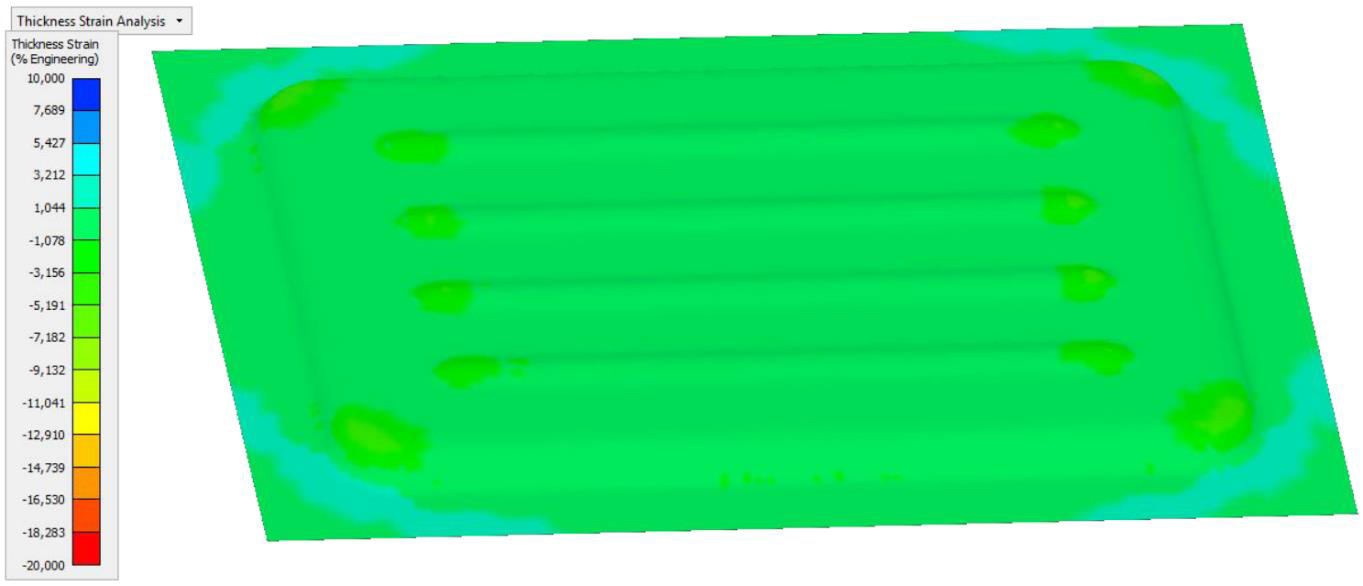
Fig. 3. Thinning of the container (engineering values in %).
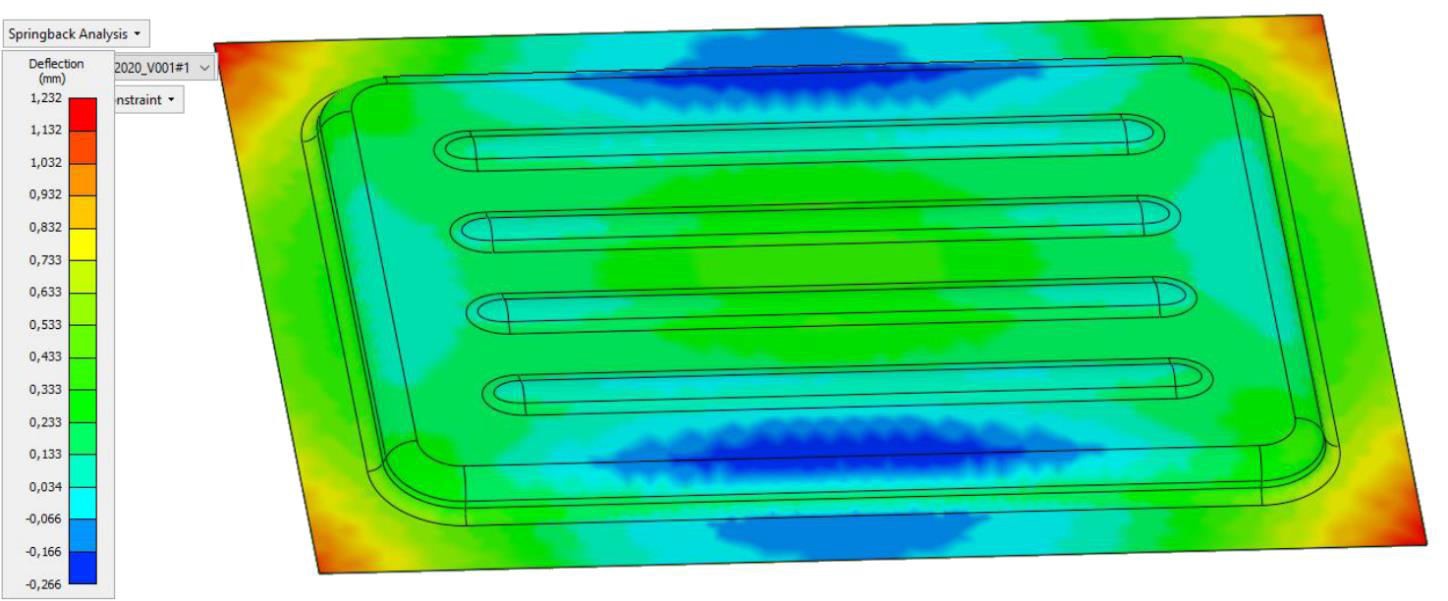
Fig. 4. Springback effect in z axis in mm.
Elements of triangle and quadrangle surface type of nonlinear stress distribution towards thickness were used. It is based on the Belytschenko-Tsay model which relies on uniform, coherent and reduced integration. Number of the elements have been optimized relatively to the computing time so the accuracy reflects the reality. Forming die contains 600510 elements and 158090 nodes, whereas the blank sheet initially contained 16500 elements and 4250 nodes obtaining about 675230 elements and 176500 nodes at the end stage of the process.
5 Stamping with an elastomer
The rubber cushion is planted in a steel or cast iron bin. The walls of this bin should be thick and strong enough to withstand the pressure exerted by the rubber during forming. The thickness of the rubber cushion should be between 150 and 300 mm. The rubber cushion can be uniform or layered. The layered cushion is made by stacking rubber sheets on top of each other in the bin. A serious advantage of the layered cushion is that the used outer sheet can be flipped over or swapped with another sheet. The rubber used for bending and stamping should have a Shore hardness of 40 to 95 ShA (Fig. 5).
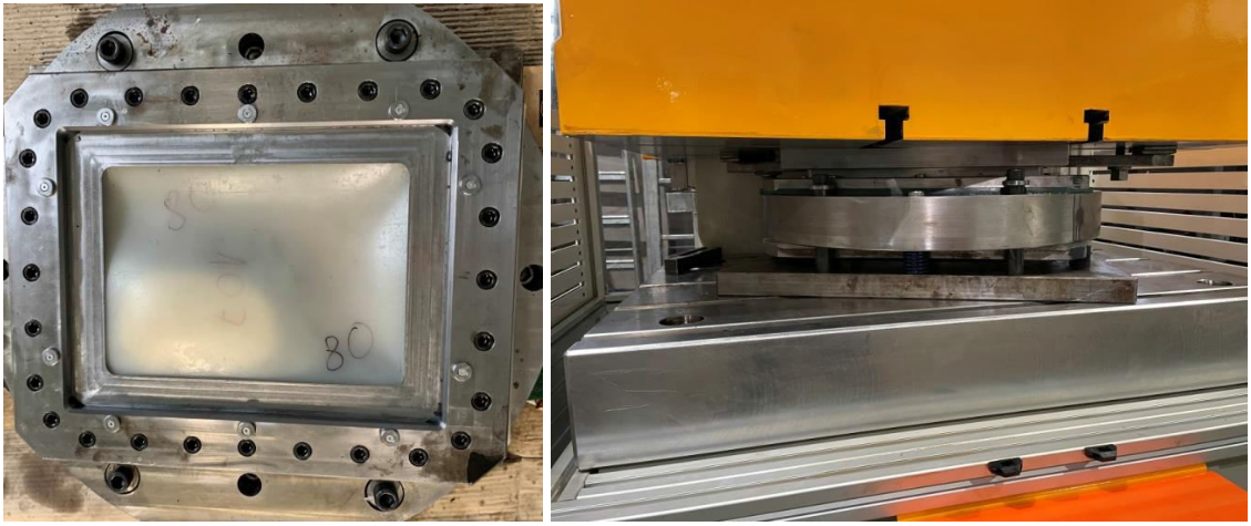
Fig. 5. The forming tool assembled with the diaphragm with an elastomeric plate (the left figure presents an open tool and the right figure presents the tool set on a hydraulic press).
The rubber block is attached to the bin in such a way that the rubber is made longer and wider than the bin opening. Pressing the rubber into the bin takes place on the press. The rubber is placed on the press table, and then the lowering slider presses the rubber into the bin (Fig. 5). The minimum rubber allowance for pressing should be approx. 1% in length and width. Shaped punches are made of various materials. Production is to include a large number of items, the punch should be made of cast iron or steel. When determining the height of the punch, it has to be taken into account that the rubber does not fill the internal sharp cavities and corners. At this point, the rubber will create natural, smooth transitions rounded with a certain radius. Due to these properties of the rubber, the punch should be so high that the lower edges of the stamped wall are slightly higher than the fillets formed by the rubber. The extreme point of the object wall should be at least 3 to 5 mm higher than the aforementioned fillet. Rubber stamping can also be used for items with shallow recesses (Fig. 6). In order to avoid folding of the edges, the material must be pressed firmly, but at the same time it must be able to slide, similar to pulling on a press [3, 4, 5, 10].
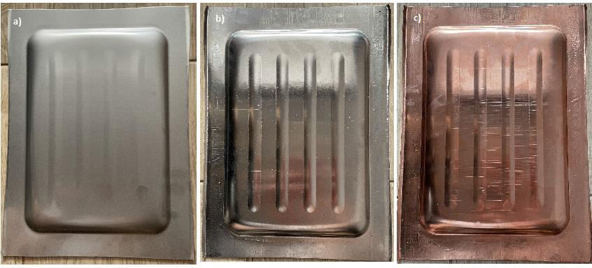
Fig. 6. The final parts after the 2000 kN press tests made of: a) steel, b) aluminum alloy, c) copper alloy
6 Conclusions
The proposed change in the method of manufacturing a container for phase change materials (PCM) with a changed geometry increasing stiffness as shown by numerical FEM analysis and the experiment is feasible under real conditions. The geometry of the PCM container forced an increase in the stiffness of the lower bottom, which was reinforced with transverse stiffeners. For a blank thickness of 1 mm, the stiffness is satisfactory, while when the panel thickness is reduced by 25-30%, the required container stiffness may be reduced. In addition, the planned change of material from steel to aluminum alloy will reduce the weight of the parts, while reducing the strength of the panel. Therefore, additional transverse stiffeners were introduced to improve the stiffness of the entire panel. In order to fulfill the extrusion of approximately 12.5 mm in the depth of the bowl, an elastomeric punch with a clamp was used using a conventional steel forming die to match the actual shape of the part. According to the assumptions, the part has a material thickness of 1 mm, which allowed to reduce the weight of the structure to a minimum.
The forming process was carried out on a servo press with a maximum pressure of 2000 kN, which was sufficient to form the desired shape of the final part. In accordance with the anticipated FEM analyzes, the drawpiece did not show any defects such cracks and springback in all x, y, z axes. The only disadvantage is the few wrinkling below 0,1 mm in the area of the subsequent cut for the assembly of the container and finally the heat exchanger.
Bending with rounding of the lower part is a relatively difficult operation. It requires a large depth of cut and the flexibility of the workpiece. To meet these requirements, polyurethane U-profiles should be used. During plastic working, the void of the U- shaped or hollow cushion causes a lateral force and a greater arc of contact, and thus a greater lateral bending force.
The forming process, as expected, required the lowest pressing force for materials such as aluminum alloy and copper alloy, and most for austenitic steel. Geometrically, despite the use of a force of 2000 kN, the ribs on the embossing of the austenitic steel container were not fully reproduced. From the point of view of strength of materials, they act as stiffeners, so 0.3 mm shallower ribs do not affect the obtained geometry. In terms of aesthetics and geometric, stamped part made from the copper alloy and the aluminum alloy meet all the assumed expectations.
Acknowledgements
The works were carried out within the LIDER IX project entitled “Development of an innovative modular energy storage system using phase change materials” with a number of 0004/L-9/17/NCBIR/2018 financed by the National Centre for Research and Development.
