1 Introduction
There is an increasing interest towards the hybrid structures, related to the possibility to obtain high performances in combination with tailored properties. In this field of research, additive manufacturing technologies play a key role due to several advantages, such as create complex-shaped components and lower prototyping costs. The present work can be contextualized in this scenario. Direct Laser Deposition (DLD) is the most suitable technology for these applications, considering that direct energy into a narrow, focused region to heat a substrate, melting the substrate and simultaneously melting material that is being deposited into the substrate’s melt pool. Unlike powder bed fusion techniques, DLD processes are not used to melt a material that is pre-laid in a powder bed but is used to melt materials as they are being deposited [1]–[3]. The capability to produce fully dense, as well as gradient or hybrid objects, makes the DLD more attractive, comparing to powder bed systems, in the manufacturing of large and/or functionally graded components [4]. Aiming to create a multi-material component with tailored properties, a hybrid system machine is used that allows combining additive manufacturing and five-axis CNC machining [5]. Moreover, due to the influence of the feedstock material on the final result of the powder-based laser additive manufacturing process, the metal powders were analyzed [6]. For this purpose, a case study is analyzed, i.e. a flange for the motive sector. The flange shows a central threaded bushing that must resist to heavy loads, while the base of the flange must be tenacious and weldable to be easily bonded to the chassis of the car. In a previous work, the authors have also described the redesign of the flange in order to obtain the desired properties but with an optimizing shape [7]. With hybrid multi-material components, the presented experimental work has the aim to meet the needs of the industry that, nowadays, requires tailored structures with high performances and specific properties in different parts using.
2 Materials and Methods
2.1 Materials and experimental set-up
The feedstock material was chosen to achieve a successful printing process in combination with the desired properties of the final product. For these reasons, the central bushing is made of Fe55TM, which is a tool steel with high strength and hardness for the desired application, and the gussets in 316L stainless steel and both are deposited on a laser-cut C40 plate-base (Fig.1).
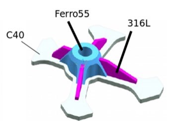
Fig. 1. The design of the multi-material flange for the automotive sector, printed in multi-material on a laser-cut plate base [7].
Near spherical shaped gas-atomized 316L and Fe55TM powders were supplied by Voestalpine Böhler Welding GmbH. Powders have been characterized according to the ASTM Standard F3049 [8]. The particle size of the powders involved in this study ranges between 55 and 145 µm, and the chemical composition of each feedstock is given in Table 1.
Table 1. Chemical composition of the used 316L and Ferro55 powders used in the additive manufacturing process.

The AM process is also influenced by the flowability of metal powder [9], which affects its behaviour in the AM process. Indeed, the spherical-shaped particles facilitate easy flow of the powder through the deposition nozzle. For this reason, the morphological, as well as microstructural and chemical analyses were carried out by using a scanning electron microscope, Hitachi TM3000, equipped with a National Instruments EDX microprobe (Oxford Instrument Swift ED3000). In addition, powders were crosssectioned, mounted, lapped, and polished with a custom-made metallographic preparation for a better investigation.
As mentioned before, a laser-cut C40 steel plate is used as a build platform for the DLD printing process. Before experiments, the substrate was cleaned with ethanol. The DLD machine is a Lasertec 65 3D by Sauer GmbH/ DMG MORI AG, a hybrid additive and subtractive machine. The system was equipped with a Coax 14 powder nozzle and a diode laser with a maximum output of 2500W. The spot diameter was 3mm, with a tophat beam profile.
Using optimized parameter based on preliminary experiments, in terms of laser-power, scanning speed and powder feed rate, tensile specimens were printed in 316L and Fe55TM in the x-y direction, three for each material to assess the repeatability.
Similarly, three flanges were printed according to the following procedure. First, the central bushing was deposited in Fe55TM, followed by CNC machining to prepare the part for the subsequent deposition of the gussets. Then, the four gussets were deposited in 316L, and finally CNC machining operations were performed to achieve the desired dimensions and surface finishing. To study the adhesion between the different materials at their interfaces, and to check for probable internal defects, metallographic samples were extracted from the flange. Cross-sections orthogonal to the printing height were mounted in a conductive thermoplastic resin (Lucite supplied by Struers) and, then, lapped with grinding discs with final polishing using diamond of 1 μm particle size.
2.2 Mechanical properties
To determine the mechanical properties, uniaxial tensile tests were carried out on 316L and Fe55TM samples, according to ASTM E8M, and uniaxial static mechanical tests on the printed flange. Tests were carried out using a Galdabini QUASAR 50 testing machine, equipped with a 50kN load cell and at room temperature. The software associated with the Galdabini machine, LabTest, allows programming the tests according to the International Standards. Since the base part in C40 is the weakest material of the part and its deformation might influence the test, a custom-made experimental set-up as shown in Fig. 2 was used, to test the strength of the part.
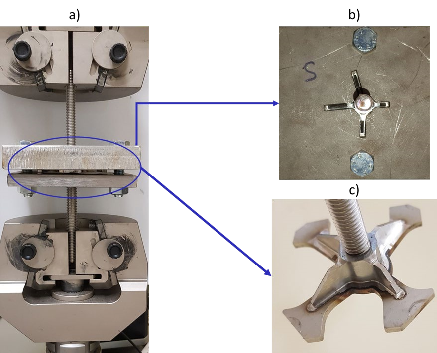
Fig. 2. The tensile test of the case study: (a) Custom-made set-up, (b) top view of the flange in the fixture, (c) the flange in the experimental test configuration.
3 Results and discussion
3.1 Feedstock characterization
Fig. 3 shows the SEM micrographs of Fe55TM powders at different magnifications in order to appreciate both morphology and defects. It is possible to observe that, although metal powders are gas-atomized, several particles are elongated and irregular in shape. In particular, Fig. 3b) pointed out the presence of very irregular shapes. Moreover, in Fig. 3c) and 3d), red arrows highlight the presence of open pores, in which it is possible to find smaller particles fit together, agglomeration of particles, broken/sliced ones, and satellite particles which are originated from the non-optimized atomization process. Consequently, the final product may contain defects that are related to the ones of the powders. Moreover, a careful analysis of the micrographs highlighted the presence of darker particles, so energy-dispersive X-ray spectroscopy (EDS) has been done. The global chemical composition shown by the EDS spectrum is similar to one of Table 1, but at the same time a punctual EDS analysis on the darker particles have pointed out that these are oxides that contain impurities such as silicon.
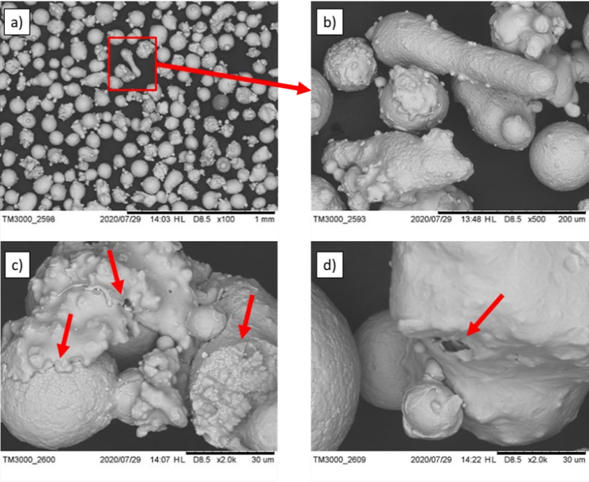
Fig. 3. Micrographs of Fe55TM powders at different magnifications showing several defects: (a) and (b) irregular shapes, (c) adhesion phenomena and broken particles, (d) internal voids.
Fig. 4 shows the SEM micrographs of 316L powders at different magnifications in order to appreciate both morphology and defects. In this case, most of the powders are spherical, although some irregular particles are depicted (Fig. 4b)). In particular, it is possible to note that dimensions are strongly different from one particle to another, but for the additive process it represents an advantage, promoting a good powder flowability. The defects are similar to the ones previously described and are highlighted by red arrows: agglomeration of particles and voids are visible in the powders (Fig. 4b),c), d)). For completeness and consistency of the presentation of the results, EDS analysis was carried out also for stainless steel powders, but the results were consistent with the chemical data present in Table 1 and have shown that powders were free of contaminations.
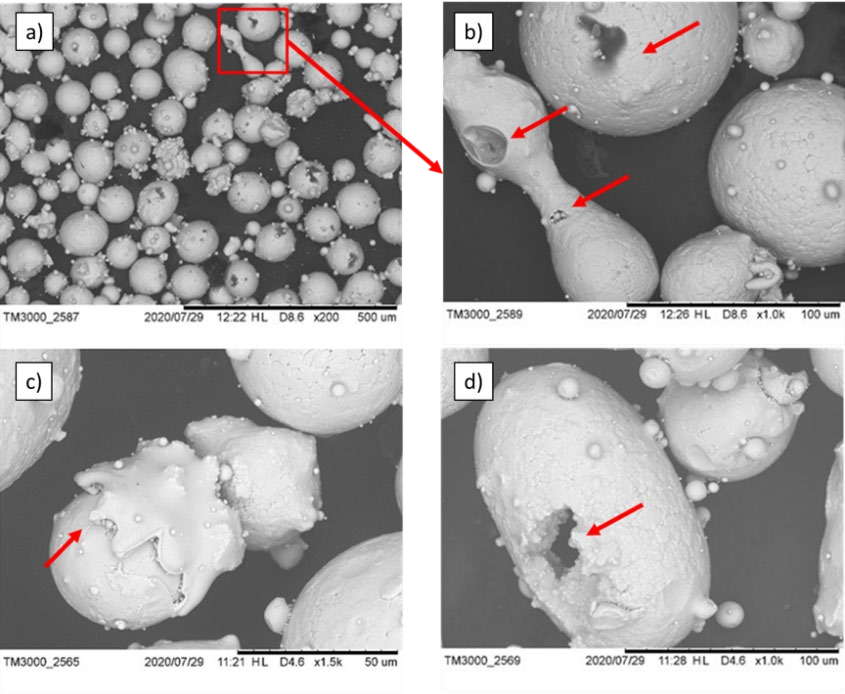
Fig. 4. Micrographs of 316L powders at different magnifications showing several defects: (a) and (b) irregular shapes, (c) adhesion phenomena, (d) internal voids.
The near-spherical shaped geometry is also evident in Fig. 5, in which the cross-sections of the Fe55 TM and 316L single particle are shown. The microstructure is made of equiaxed grains, typical of gas-atomized steel powders, and no internal defects can be observed.
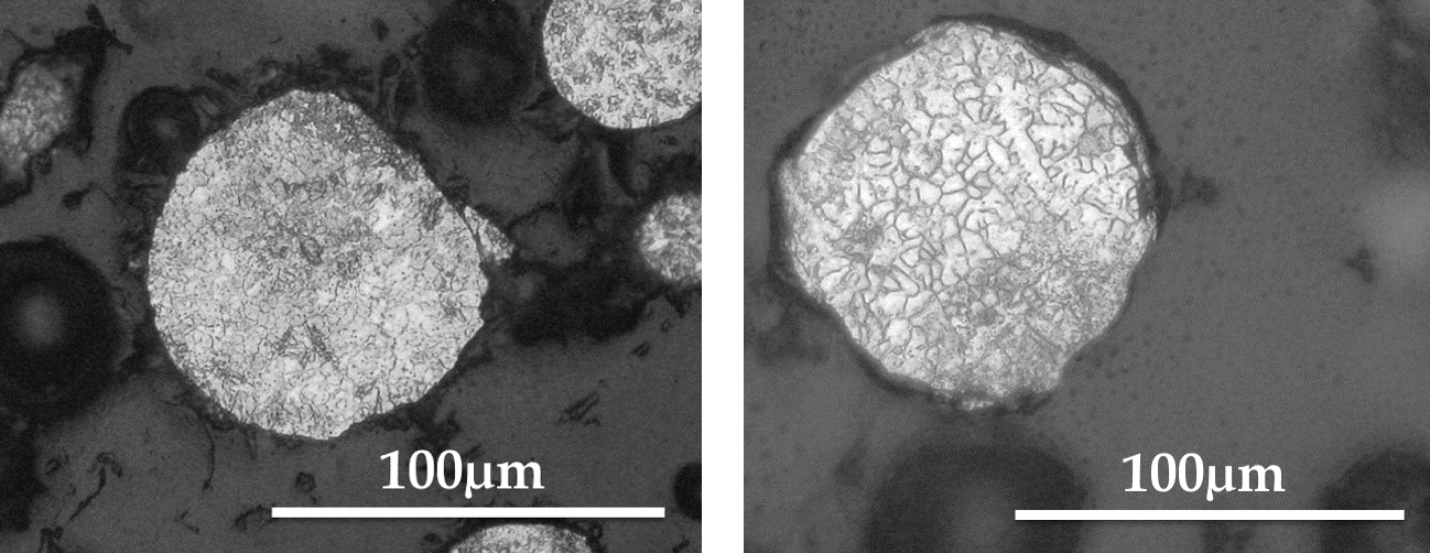
Fig. 5. Micrographs of cross-sections of Fe55TM powder (left) and 316L powder (right).
3.2 Mechanical characterization
Although at the beginning Fe55TM and 316L are printed according to the standard size and according to above-mentioned direction of growth, for what concerns the Fe55TM tensile tests, samples slipped and it was not possible to do the tests with standard dimensions due to the high hardness and strength of the material, as consequence authors opted in favor of smaller dimensions. Stress-strain curves of the 316L and Fe55TM tensile tests are presented in Fig 6; the maximum stress achieved is 655 MPa, for 316L samples, and 2033 MPa for Fe55TM. This result are comparable to the mechanical properties of samples produced in the conventional manufacturing process [10].
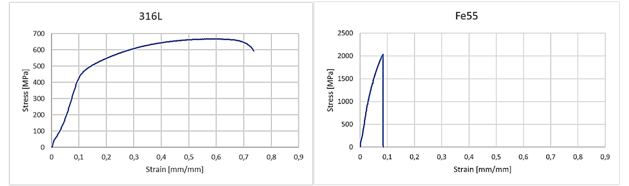
Fig. 6. Stress-strain curves of samples additively printed in 316L (left) and Fe55TM (right).
3.3 Flange characterization
To assess the adhesion between the Fe55TM bushing, the 316L gussets and the C40 plate, the specimens were sectioned and observed, and the result is shown in Fig. 7. Although the powders showed several defects, during the process these disappear and it is possible to see that the final product are free of defects, and no porosities are detected specifically in the interfaces.
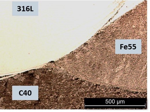
Fig. 7. Micrograph of the Fe55TM, 316L, and C40 interfaces of the cross-section of the flange printed by DLD.
In Fig. 8, it can be observed a micrograph of the interface between the printed materials in order to verify the quality of the material joint itself. Moreover, in the Fig. 8, micro-indentations with the values of the microhardness are shown. It is important that no discontinuity or voids were observed. It is also noteworthy that in some locations partial blending of materials was observed at the interfaces. This could be attributed to the Marangoni effect at the bottom of the melt pool [11], which may lead to irregularities in hardness profile, as it can be seen in this image.
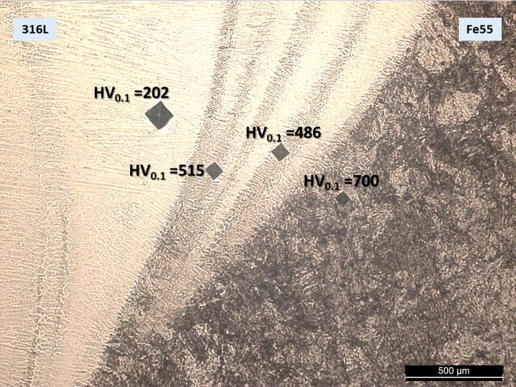
Fig. 8. Micrograph of an interface between the 316L stainless steel and the Fe55TM tool steel. Micro-indentation are shown with their respective values.
The adhesion between materials and the effect of hardness were studied in the next stages of the research by performing a static mechanical test. Microhardness profiles are presented by the authors in a previous study [5]. In Fig. 8 it is possible to note the raise of the hardness from 316L to Fe55TM, passing through a blended zone. In addition, for what concerns the uniaxial static mechanical tests, all the three samples reached a load of 47 kN without breaking the specimen, as reported by the LoadDisplacement curve in Fig. 9. The results of the tests are more than satisfactory. Precisely, for the application of the car flange, the maximum load achieved is over the necessary requirements, for this reason and to preserve the load cell of the tensile test equipment, the test has been stopped. The diagram can be divided into two zones, these zones show different slopes, which suggests different mechanical behaviour. The zones are indicated as phase I, phase II. Phase I is quite linear, with a slope representing the initial linear stiffness of the joint created between the printed materials and the plate. It is probably related to response to the load that is distributed between the central bushing in Fe55TM and the four gussets in 316L. In phase II, a
difference in the slope from the first branch is detected, in particular, it is slightly major and shows a predominance of the Fe55TM central bushing in response to the increasing applied load. Indeed, since the flange is composed of different materials, the test highlights the different mechanical behaviour of them and it results in two different slopes.
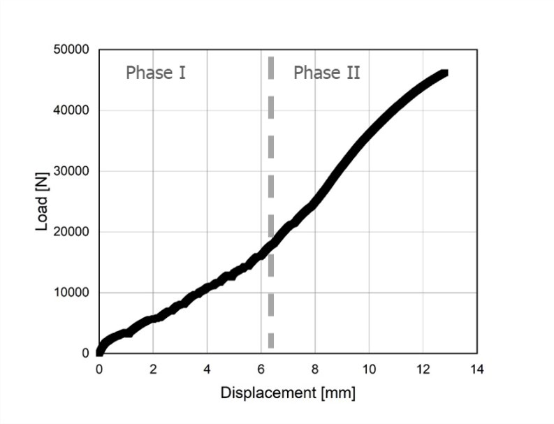
Fig. 9. Load-Displacement curve of the flange of the car printed in different material.
4 Conclusions
In this work Direct Laser Deposition was used to create tailored components. The first step is represented by the morphological study of the feedstock powders and the investigation of the mechanical properties of samples printed with the characterized powders, in order to realize a hybrid component. In this context, a case-study is presented: a flange for the automotive sector with tailored properties. It is successfully printed, at first depositing Fe55TM for the central bushing to resist heavy load, then gussets in 316L to increase the stiffness and use a C40 plate-base to ensure the weldability. More than one advantage of the DLD process has been highlighted and, hence, the following conclusions can be drawn:
-
This process has ensured a metallurgical bonding between layer and substrate, and between the different materials. The continuity at the thee interfaces is demonstrated, indeed no distinct discontinuity or voids are detected in the multi-material component and a partial blending of the materials is provided. Indeed, after the analysis and the characterization of the particles, it is demonstrated that the use of feedstock powders with irregular shapes and sizes in the DLD additive process doesn’t entail defects, such as voids, in the final component.
-
The mechanical properties of both the single-material and multi-material components are provided, demonstrating that with the use of the DLD additive process, it is possible to achieve excellent mechanical properties, and optimize the properties according to custom requirements.
Acknowledgements
This research was supported by PON research AMICO (ARS 01_00758). The authors thank the MIUR (Italian Ministry of University and Research) for funding. The authors would also like to show our gratitude to FCA Italy for the support.
