1. Introduction
Nowadays, Ti-6Al-4V is the most commonly used titanium alloy. Indeed, over half of the titanium alloy market is based on Ti-6Al-4V [1]. It belongs to the group of (α+β) alloys exhibiting high strength at medium density and excellent corrosion resistance, and is used in various sectors such as aerospace, automotive, medicine, chemical industry and power generation [2,3]. Such lightweight and strong alloys are especially suitable for highly loaded structures where weight reduction is a way to improve efficiency [4,5]. Additive manufacturing (AM) of titanium alloys has gained interest in the aerospace industry because of its potential for new design options as well as repair and hybrid manufacturing. AM can be used to manufacture parts such as turbine blades, blade integrated disks and combustors [6]. The typical deposition rate of Ti-6Al-4V using LMD is, however, below 1 kg/h and is commonly used for repair purposes, as it is not cost-effective for entire component build-up. Laser material deposition (LMD), also known as direct energy deposition (DED) or laser cladding, is an additive manufacturing method in which complex geometries can be formed by the multilayer arrangement of subsequent layers [1,2]. In this process, a laser beam is passed over the surface of the component, which is selectively melted. As seen in Fig. 1a, metal powder is injected into this molten pool with the aid of a carrier gas, typically a noble gas such as argon, which produces a molten metallurgical compound [3,4]. The addition of a noble gas as a shielding gas along the powder stream prevents the degradation of the powder and the molten bath. While it is obvious that near-net-shape technologies, such as AM, could lead to a more resource-efficient production than traditional production [4,7,8] [9], production costs in AM grow quickly with part size increases [10]. A way to overcome this is to increase the deposition rate on the scale of several kg/h.
In the present work, high-deposition-rate LMD (HDR-LMD) was equipped with a high-power diode laser and a zoom-optic for a large laser beam spot to improve the systematic ability of massive injected powder particles to melt. A powder nozzle was designed to meet the powder stream distribution requirements. By using the energy density index, the process window for the HDR-LMD process (deposition rate > 300 cm³/h) [11] was quantitatively determined. In addition, several systematic experiments were carried out to improve the bonding and porosity reduction of deposited HDR-LMD Ti-6Al-4V material, including process parameter dependence on track geometry and powder performance. This paper deals with understanding how the process conditions influence microstructure and texture evolution.
2. Material and Methods
2.1 Laser material deposition using powder
As shown in Fig. 1a, metal powder fed by an inert gas (typically argon) is introduced into the focused laser beam that generates a melt pool on the surface. The carrier gas and an additional gas stream through the beam path create an inert gas atmosphere around the melt pool [4,12]. When the beam moves on, the melt quickly cools down and solidifies [13]. While the inert gas fed through the powder feed nozzle shields the melt pool, the rest of the part is exposed to the surrounding atmosphere and the surface is oxidized. To avoid this oxidation, a global inert gas atmosphere was created by using an inert gas chamber filled with argon (Fig. 1b). The processing head is inside this chamber. As beam source, a 12 kW diode laser LDF 12000-100 from Laserline GmbH was used.
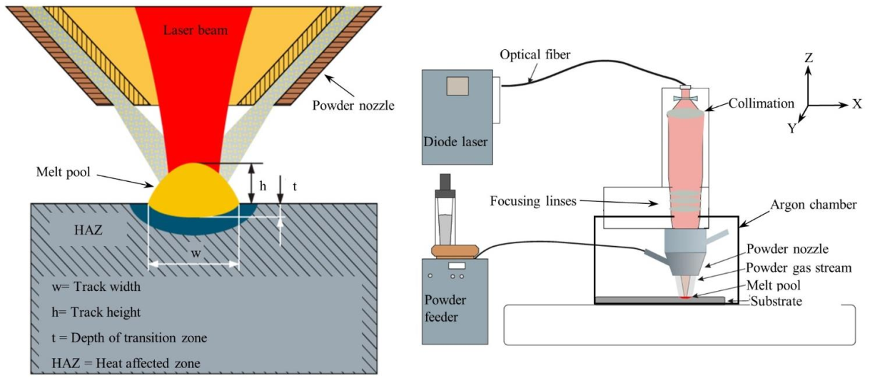 Fig. 1. Experimental set-up with a) schematic diagram of powder laser material deposition (p-LMD); b) LMD set-up with laser beam source, powder feeder, optic, powder feed nozzle and inert gas chamber [14].
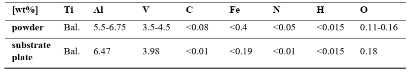
The Ti-6Al-4V powder material used for the experiments was supplied by TLS Technik GmbH. The measured chemical composition is listed in Table 1. The powder material was produced in the electron induction-melting gas atomization process (EIGA) and has a spherical particle shape and a particle size distribution between 45 and 90 µm. The Ti-6Al-4V substrate used in the LMD process was supplied by ATI Specialty Materials. The dimensions were 250 mm x 100 mm x 10 mm. The chemical composition is listed in Table 1. Prior to usage, the substrate plates were sandblasted to clean the surface and improve the absorption of the laser radiation.
Table 1. Chemical composition of the powder and substrate plate.
2.2 Geometrical and microstructural analysis and hardness measurements
A Zeiss 1540XB FE-SEM, Olympus BX53M light microscope, equipped with the software Stream Motion, and an industrial CT Nikon (model METRIS/XTEK/XTH320LC) were used for microstructural analyses. To reconstruct the primary β-grains size from the measured alpha phase EBSD data, the Burgers orientation relationship (BOR) [15] and a modified approach described in [16] and [17] were used. The hardness according to Vickers [DIN EN ISO 6507] was measured with a Q30A Plus micro hardness tester from ATM Qness GmbH. The specimens were loaded with a test force of 2.942 N and an exposure time of 15 seconds with a load of 300 g (HV 0.3).
2.3 Porosity measurement
Porosity measurements were performed via quantitative optical metallography for cross-sections of all deposited tracks with an Olympus optical metallography microscope and Stream motion software. Porosity determination is based on the area ratio of all pores in the cross-section.
2.4 Temperature Measurement via Thermal imaging
In this work the ImageIR © 7350 infra-red camera system (IR camera) from InfraTec GmbH was used to capture the LMD process thermal images. The temperature field of a single depositing track can be obtained by using the IR camera and, therefore, are used for the analysis of molten pool state and measurement of the sample temperature. The IR camera is focused on the LMD deposition path plane with an angle of inclination at 30°. The IR camera was set to capture 100 Hz images. The LMD build-up strategy of a part with Ti-6Al-4V alloy was bidirectional by 90° rotational scanning pattern.
3. Results and discussion
3.1 Process development
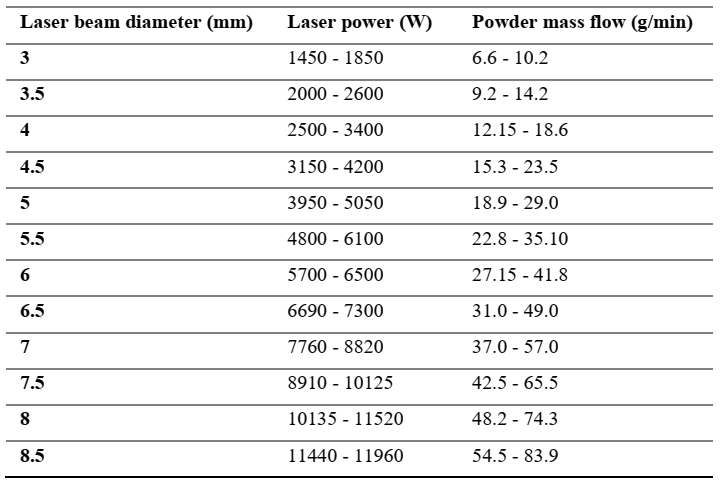
We investigated the as-built single-track microstructures of a Ti-6Al-4V part manufactured with LMD, focusing on phase formation and grain coarsening. The development of defect-free single tracks is essential for the production of layers and bulk samples. Single-tracks created in the main experiments were examined regarding their geometry, microstructure, porosity, hardness, melting depth and heat-affected zone. Individual tracks were produced to find the process window, and with the help of designated parameters, volume samples were produced. In addition, tracks and their properties were analyzed. The influence of the process parameters (feed rate, laser beam diameter was investigated. The h/w-ratio, microstructure, porosity, hardness, melting depth and heat-affected zone were evaluated. Only one parameter was varied at a time, while the other two parameters were kept constant. Pores and bonding defects are often the result of insufficient laser power. However, increasing the laser power too much causes evaporation of aluminum and, thus, porosity and a change in composition. For this reason, single tracks with moderate laser power and feed rate were produced and analyzed in a preliminary study, in order to determine the minimum laser power for creating defect-free tracks. Based on the obtained results, the powder feed rate and laser beam diameter were increased in the main study to achieve a high-deposition-rate. In addition, the laser power was varied. The laser power and the powder feed rate were scaled accordingly. The scanning speed was kept constant. The laser power was varied for the laser beam diameter of 3 mm in a range of approximately 1450 W - 1850 W and the powder feed rate ranged between approx. 6.61 g/min and 10.2 g/min. A complete list of the processing parameters is given in Table 2.
Table 2. LMD process parameters
3.2 Influence of laser power on track geometry
The aim was to achieve an aspect ratio (height vs width of a track: aspect ratio Ar) between 0.25 und 0.16. These aspect ratios lead to an applied tangent with an angle of about 45 degrees to the substrate and, thus, prevent bonding defects between adjacent tracks. An aspect ratio of 0.25 ensures a higher build-up. As illustrated in the Fig. 2, when laser power was increased, the track widths acted likewise. The black lines show an aspect ratio of 0.25, red lines 0.2 and blue lines 0.16. The laser power is shown in relation to aspect ratio, track width and track height. The effects of the laser power on the track height show a dissimilar tendency compared to conventional LMD. For the HDR-LMD process, increasing laser power and powder feed rate did not affect the track height. The melt flows better at higher temperature when energy input is increased and the track width and height aspect ratio are varied. In this way, if an increased laser power is applied, the molten pool becomes wider as a result of the heavier radially outward melt flow. Consequently, a smoother transition wetting on the substrate allows a wider track width. Attributed to a raised powder feed rate, the track width increases slightly. Moreover, track height is stable while the powder feed rate increases.
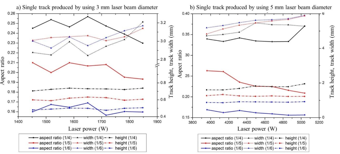 Fig. 2. Effects of laser power on the aspect ratio, track width and track height for a) 3 mm and b) 5 mm laser beam diameter with different aspect ratio.
The aspect ratio drops from 0.35 to 0.16 when the laser power is raised from 3200 W to 4200 W. As can be seen in the graphs, there is a determined trend with the given parameters: between aspect ratio, track height and track width with the increasing laser power. When the laser power increases, track height remains steady.
3.3 Microstructure (incl. EBSD, thermal imaging)
The as-built microstructures in Ti-6Al-4V produced by AM can be quite complex, mainly due to solid state phase transformations of the solidified β-phase. Typical structures are Widmanstaetten basket-weave [18,19], acicular or martensitic microstructures [20–22] depending on the process conditions.. Fig. 3 shows the fine basket-weave morphology inside primary β-grains in a single layer of a sample produced by LMD.
The EBSD analysis in Fig. 4 shows that the primary β-grains have a columnar form. The growth direction of the grains is determined by the temperature gradient at the solid-liquid interface, which is strongly directed into the solid material of the substrate. Large size columnar grains, therefore, grow parallel to the direction of cooling. Depending on specific laser power and powder feed rate, the primary beta grain size varies from a few hundred microns to several millimeters.
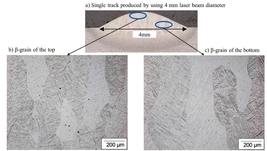 Fig. 3. Microscope images of a) single track produced by a laser beam diameter of 4 mm; laser power: 3120 W, powder feed rate: 14,61 g/min, scanning speed: 1500 mm/min, b) microstructure at the top and c) microstructure at the bottom of the track.
The α microstructure formed inside the prior β-grains varies depending on the cooling rate and the corresponding thermal cycles. Often, a phase of discontinuous grain boundary α is also observed at the boundaries of prior β-grains [23]. Rapid solidification is a consequence material added in a layer by layer fashion and consists of wide prior β-grains that grow epitaxially across several layers [24–26]. In addition, the cooling rate depends on several factors including part geometry, position in the part, process gas flow rate, laser power, laser scanning speed, and build-up strategy of the layers.
Grain growth appears during solidification from previously deposited AM layers and ultimately regulates the crystallographic nature of the AM structure via partial or complete remelting of the previously formed underlying layer [27]. Throughout solidification, the structure near the melt pool boundary is controlled by the base metal. However, further from the melt boundary, the microstructure is controlled by competitive growth. Competitive growth appears among dendrites with various crystallographic orientations in the polycrystalline materials [28]. Fig. 4 shows the orientation with respect to the z-axis (sample normal) of the α phase, measured by EBSD, in inverse pole figure coloring maps, from areas just above the base plate interface. Below, the results of primary β-grain reconstruction are shown in IPF-Z coloring maps.
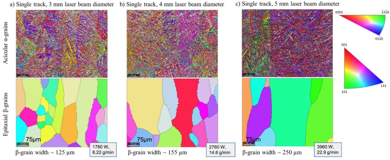 Fig. 4. IPF coloring (with respect to z-axis) of EBSD data for a) 3 mm b) 4 mm and c) 5 mm single tracks; upper pictures show the α-grains (IPF-Z-map) and the lower pictures show the reconstructed β-phase IPF-Z grain maps (smoothed).
In AM, the substrate acts as a heat sink. Therefore, conduction heat transfer through the substrate drops progressively as layers are deposited, resulting in an increase in the peak temperature for the upper layers. Since the laser beam moves, the temperature contours are stretched out behind the heat source and compressed in front of the beam. A simple block (40 x 40 x 20 mm³) was built in order to plot the time-dependent graph (see Fig. 5) of the temperature changes between layers. The temperature of the manufactured block was measured with the thermal camera during the build-up. The points denote different time intervals during the production of the sample. For example, point two implements layer three. It took 300 seconds to produce three layers. Five points are placed on the part digitally at equal intervals: P1 = first layer, P2 = third layer, P3 = sixth layer, P4 = ninth layer, P5 = thirteenth layer.
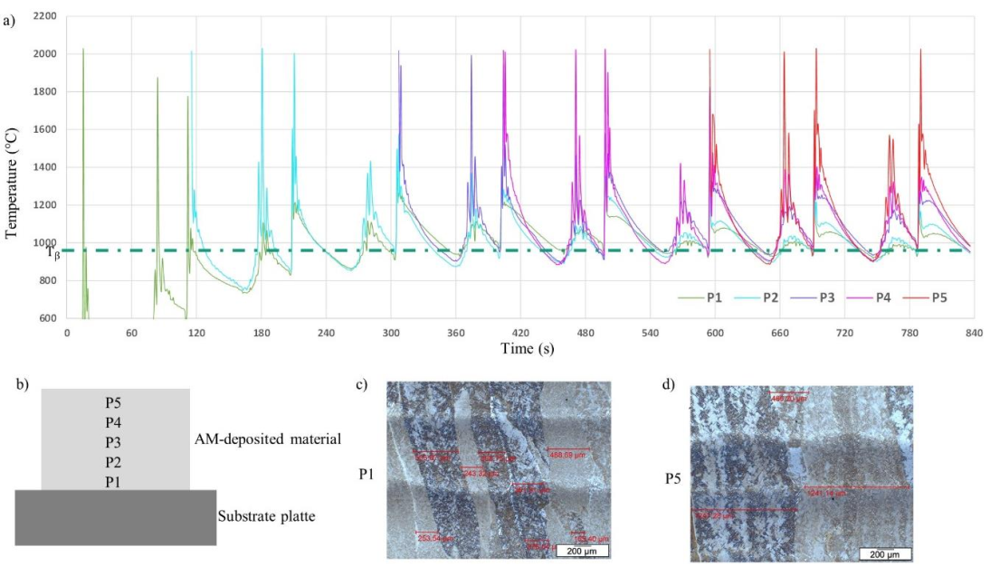
Fig. 5. a) Temperature profile of b) solid body, P1; first layer, P2; third layer, P3; sixth layer, P4; ninth layer, P5; thirteenth layer, fabricated with 3 mm laser beam diameter; laser power 1780 W; powder feed rate 8.22 g/min; scanning speed 1500 mm/min, the corresponding microstructure of c) P1(bottom) and d) P5 (top).
The microstructure of the cross-section of the LMD Ti-6Al-4V parts is caused when previously deposited material is reheated during the subsequent deposition process. This leads to microstructural coarsening. Fig.5 c and d show this clearly from the first layer of the sample to the thirteenth layer. The β-phase coarsening appears as the temperature increases during deposition, a result of the constant laser energy input during the process. Martensite is expected when the material cools down from temperatures above the β-transus temperature (Tβ =994 °C) faster than 140 °C/s and below the martensite starting temperature Ms=575 °C [29]. Therefore, the β-transus temperature is indicated by a green dashed line in the plot (Fig. 5a).
3.4 Hardness measurement
Fig. 6 a) shows the micro-hardness tested within selected single tracks in terms of how laser power and the increasing beam diameter influence the hardness. The micro-hardness values measured for single tracks are approx. 420 HV for 3 mm laser beam diameter, 390 HV for 4 mm laser beam diameter, and 375 HV for 5 mm laser beam diameter. The hardness level in the different tracks corresponds with the decreasing cooling rate when the laser beam is increased from 3 to 5 mm. For an additional 3 and 4 mm a gradient of hardness occurs within the single track, which can be attributed to the fact that the cooling rate is not constant along the solidification front; rather, it is lowest at the bottom and highest at the top. This can indicate that martensitic transformation is favored at the top and regular α formation at the bottom, which could explain the hardness drop across the track. For 5 mm no gradient can be seen, which indicates that no martensitic transformation has occurred.
Fig. 6 b) and c) show hardness mapping of blocks. The average hardness within the block built with a 3 mm laser beam diameter is 327 HV, and 324 HV for the 4 mm laser beam diameter. The hardness is higher than that of the forged substrate plate (300 HV0.3).
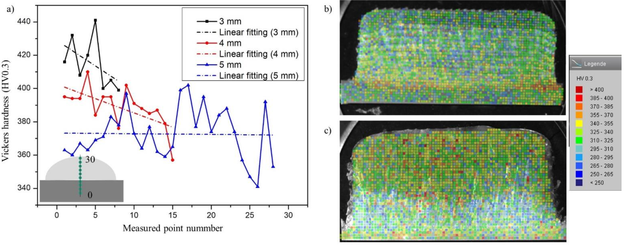 Fig. 6. a) Hardness test results of single tracks fabricated with different laser beam diameters; the hardness distribution of near-net-shape dense components with b, c) hardness mapping within a cross section of block; b) built with 3 mm laser beam diameter c) built with 4 mm laser beam diameter.
Within the blocks hardness levels can be identified related to the thermal history (actual temperature, cooling rate, heat accumulation), which depends on the process conditions and in turn, affects the final microstructure. The hardness values of the region between the substrate and the first layers vary between 355 HV to 400 HV. Here, the cooling rate is highest since the substrate is at RT and acts as an effective heat sink. In the intermediate zone it is between 300 HV to 355 HV. The cooling rate decreases due to heat accumulation, and reheating of subsequent layers lowers the hardness. In the top region the hardness is around 295 HV to 340 HV. The harder zones of deposited material correspond to the martensitic microstructure formed after rapid cooling, while softer areas correspond to the Widmanstaetten microstructure (basket-weave) formed at slower cooling.
3.5 Porosity analysis
The porosity of test series (seven different values of laser power and three different values of powder feed rate) for 3, 3.5, 5 and 5.5 mm laser beam diameter is shown in Fig. 7. The lowest porosity results for large beam diameters (< 0.2 %). For the smaller beam diameters and the lower laser power, the porosity levels are slightly higher, probably because the melt pool does not exist as long as for larger beam diameters, leaving less time for pores to escape from the melt [30].
The effect of increasing powder feed rate at constant laser power is also obvious. The porosity increases since the amount of laser power is not sufficient to melt all particles completely, leaving bonding defects inside the volume. However, this effect is very pronounced only at the lowest power values used in the experiments.
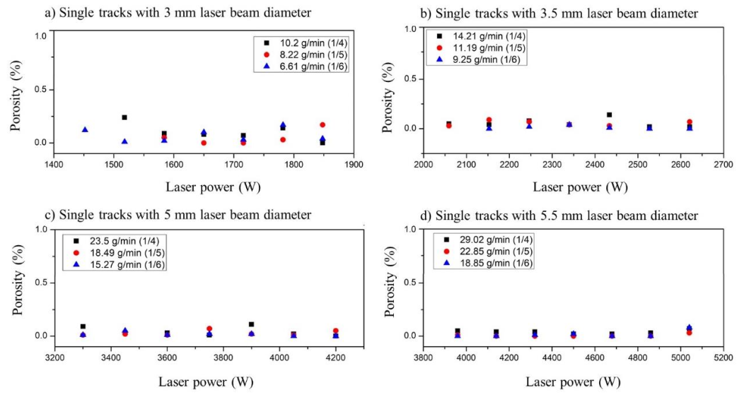 Fig. 7. Effects of laser power and powder mass flow on porosity for a) 3 mm, b) 3.5 mm, c) 5 mm and d) 5.5 mm laser beam diameters.
4. Conclusions
The aim of this paper is to investigate the influence of high-deposition-rates on the microstructure, hardness and porosity of Ti-6Al-4V single tracks and bulk volumes produced by the laser material deposition process. Higher deposition rates than the typical ones used for repair processes (below 1 kg/h) were achieved by enlarging the laser beam diameter, increasing laser power and powder feed rate.
The knowledge gained in the course of this work shows that it is possible to generate defect-free volumes at high-deposition-rates up to 5 kg/h. The volumes have a density of 99.98 %.
In the course of this work, we found that the microstructure is influenced by the process conditions where beam diameter, laser power and thermal history of each layer play an important role. In all layers, large primary β-grains form across the layers and are aligned strongly along the main route of heat transfer into the solid volume, indicating that anisotropic mechanical properties may occur (still to be determined). During solid state transformation α (basket weave) or α martensite (needles) form depending on the local cooling rate.
The micro-hardness measured in the deposited area (approximately 330 ±10 HV) is slightly higher than the typical hardness of forged Ti-6Al-4V. This effect is related to the higher cooling rate in AM.
Acknowledgements
The authors gratefully acknowledge the financial support by the Federal Ministry for Economic Affairs and Energy (BMWi) for the LuFo project SAMT64 “Forging and additive manufacturing as a process combination for the resource-efficient production of aerospace structural components made of Ti-6Al-4V on flexible production scales”.
